40 Creating Transformations with the XSLT Map Editor
This chapter describes how to use the XSLT Map Editor to create, design, and test data transformations between source schema elements and target schema elements.
This chapter includes the following sections:
40.1 Introduction to the XSLT Map Editor
The XSLT Map Editor enables you to edit XSLT stylesheets using a graphical editor. It also provides the feature to directly edit the XSLT source.
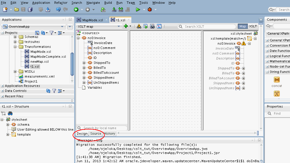
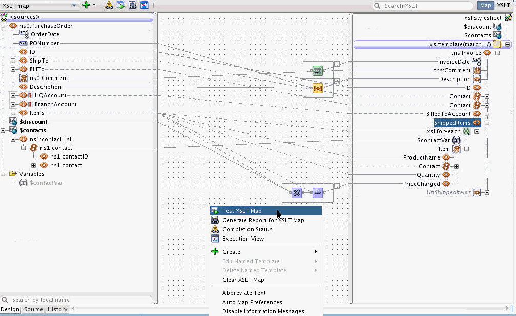
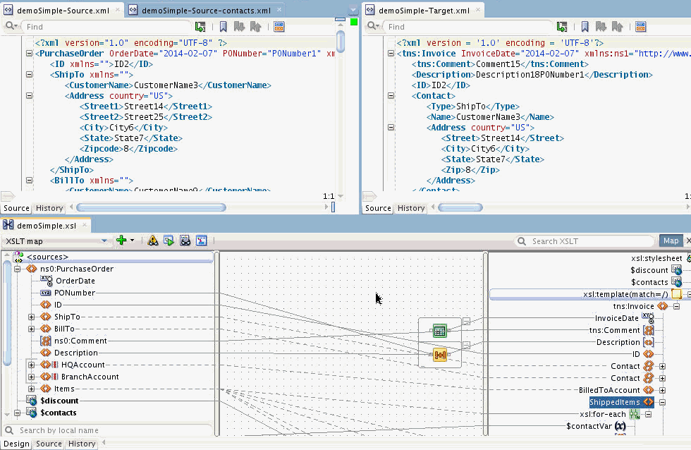
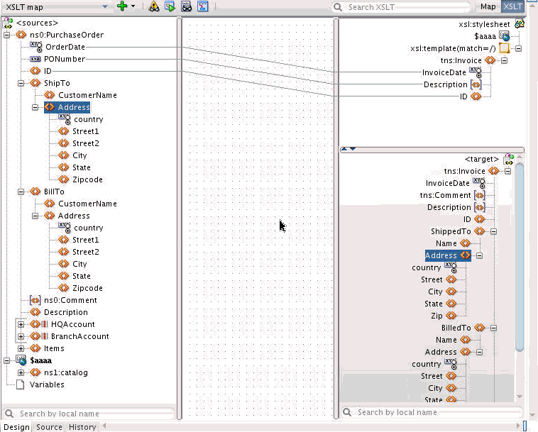
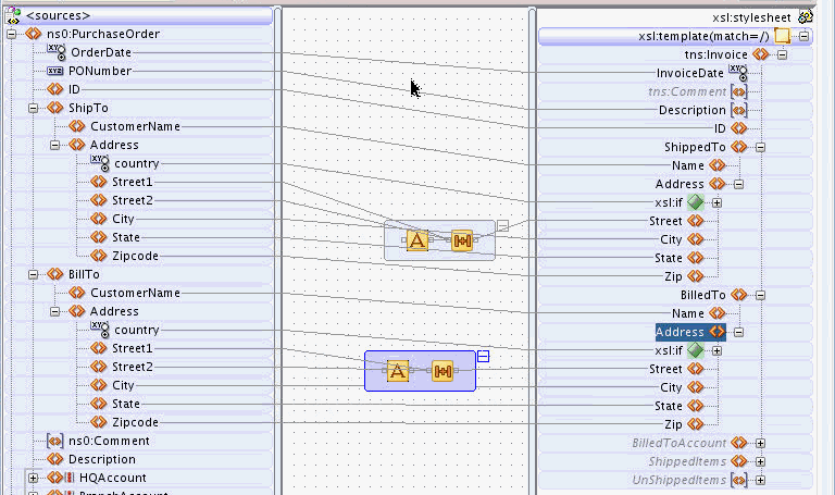
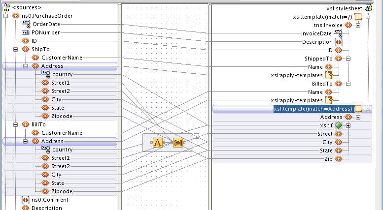
Figure 40-1 shows the XSLT Map Editor. You can switch between the graphical editor and the source view using the tabs at the bottom of the editor. Click Design to edit using the graphical editor. Click Source to edit using the source editor.
You can move back and forth between the Source and Design tabs. Any change made under one tab is reflected in the other tab. A History tab is also available to enable you to view the revision history, and revert to any point in the edit history.
The XSLT Map Editor fully supports XSLT 1.0 and XPath 1.0.
If you want to use XSLT 2.0, then you can change the XSLT version in the source view.
All XSLT 2.0-specific constructs must be added in the source view. You can then choose to switch to the design view, and continue to edit the map. XSLT 2.0-specific constructs are shown in design view, but can be modified only in the source view. XPath 2.0 constructs can also be added in the design view. However, XPath 2.0 constructs are not parsed into separate graphical elements in the design view. You must edit the full XPath statement in text form.
The XSLT Map Editor provides the following edit views under the design view:
-
Map View
-
XSLT View
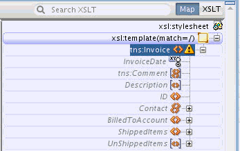
You can switch between the two views using the buttons at the top right hand corner of the XSLT editor. Click Map to use the traditional Map View of the XSLT editor. Click XSLT to use the XSLT View for more complex XSLT maps.
40.1.1 Using the Map View
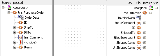
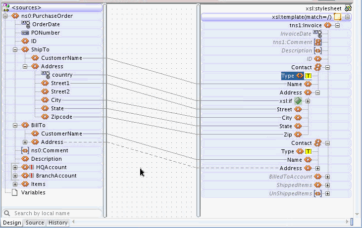
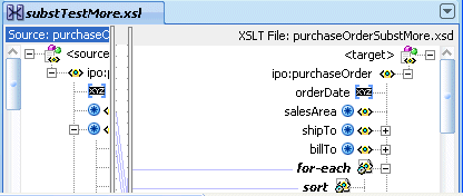
Figure 40-1 shows the Map View of the XSLT Map Editor. The left pane contains the source tree representing the incoming source XML document. The source tree can be created from an XSD schema file or a sample XML file.
The center pane, or the canvas, is the place where you drop XPath expressions and functions that can be mapped to XSLT elements.
The right pane is the target pane representing a merged view of the XSLT being created, and the target tree that represents the target schema. The target tree can be created from an XSD schema file or a sample XML file.
The grayed nodes, in italics, in the target tree represent nodes that haven't been mapped yet. These nodes are not part of the XSLT, and are displayed for convenience. Once a grayed node is mapped, it appears in regular font, and gets represented in the XSLT map.
Map View supports drag-and-drop mappings from source tree to target tree. Map View also supports XPath function calls and XSLT statements such as xsl:if and xsl:for-each.
As Map View does not separate the XSLT statements from the target tree, it is limited to the following:
-
Only one XSLT template rule with the
match='/'attribute is supported. -
The following XSLT statements are supported:
xsl:for-each, xsl:value-of, xsl:text, xsl:if, xsl:choose/when, xsl:variable and xsl:param.
Use the XSLT View for complex XSLT statements that require separating the XSLT statements from the target tree.
40.1.2 Using the XSLT View
The XSLT View is a more advanced mode that enables you to separate the XSLT statements from the target tree document. This enables you to create complex XSLT statements without leaving the design view. Source and target schemas are optional in the XSLT View.
The XSLT View includes the same panes as the Map View, except that the right target pane is divided into two panes. The top pane is called the XSLT pane and the lower pane is called the target pane. If no target schema is defined, then the lower pane is not shown. If no source schema is defined, the source pane is still displayed to enable you to add parameters and variables, whose values can be referenced by the XSLT.
In XSLT View, you can create any series of XSLT statements without having to intersperse these statements around target tree nodes. For instance, in the 11g mapper, all xsl:if statements had to contain a single target output node. In XSLT View, the xsl:if statement can be used anywhere, and can contain any other XSLT statement.
The XSLT View supports all XSLT 1.0 statements. The XSLT View also supports multiple template rules with or without source and target schemas. The XSLT View enables you to graphically display and edit any XSLT stylesheet, irrespective of the complexity involved.
40.1.3 Using the Components Window
The Components window contains all the XPath functions and XSLT elements and templates that you can use in your XSLT map.
The Components window is located at the upper right-hand corner of Oracle JDeveloper, by default. If the Components window does not appear, click Components under the Window menu to display the Components window. You can optionally choose to drag the Components window to any convenient location in the JDeveloper window. You can also resize the Components window, as desired.
The Components window organizes these functions, elements, and templates under the following categories:
-
Advanced XPath:
-
General XPath:
-
XML:
-
XSLT Elements:
-
XSLT Templates:
-
All Pages:
-
User Defined:
-
My Components:
40.1.4 Using the Properties Window
The Properties window shows the content and properties of the item selected in the XSLT Map Editor. Some of these properties can also be edited.
The Properties window is located below the XSLT Map Editor, by default. If the Properties window does not appear, click Properties under the Window menu to display the Properties window. You can optionally choose to drag the Properties window to any convenient location within the JDeveloper window. You can also resize the Properties window, as desired.
The Properties window, in general, can be used to display and edit the properties of the following items:
| Selected Element in Editor | What is Shown in Properties Window | Whether Editable (Yes/No) |
|---|---|---|
|
Source tree node |
Schema Information for the selected element or attribute. |
No |
|
Target tree node |
Schema information for the selected element or attribute. |
No |
|
XSLT tree node: XSLT element |
XSLT element attributes and their values |
Yes |
|
XSLT tree node: literal element or attribute |
Literal element or attribute name and namespace |
Yes |
|
XPath expression folder in Canvas pane |
Full text XPath expression |
Yes |
|
Function icon within expression folder in Canvas pane |
XPath field for each parameter of the function |
Yes |
|
Line connecting source and target node |
Full text XPath expression |
Yes |
40.2 Creating an XSLT Map
XSLT maps can be created from scratch, or from other editors such as BPEL, BPM, and Mediator.
40.2.2 How to Create an XSL Map File in Oracle BPEL Process Manager
An XSLT Transform activity enables you to create a transformation using the XSLT Map Editor in Oracle BPEL Process Manager. This tool enables you to map one or more source elements to target elements. For example, you can map incoming source purchase order schema data to outgoing invoice schema data.
To create an XSL map file in Oracle BPEL Process Manager:
-
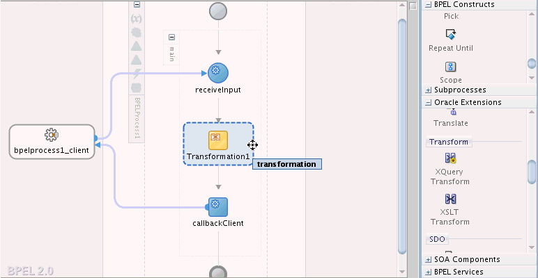
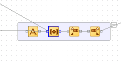
From the Components window, drag an XSLT Transform activity into your BPEL process diagram. Figure 40-2 provides an example.
-
Double-click the XSLT Transform activity.
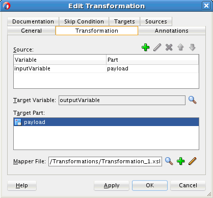
The Transform dialog shown in Figure 40-3 appears.
-
Specify the following information:
-
Add source variables from which to map elements by clicking the Add icon and selecting the variable and part of the variable as needed (for example, a payload schema consisting of a purchase order request).
Note:
You can select multiple input variables. The first variable defined represents the main XML input to the XSL map. Additional variables that are added here are defined in the XSL map as input parameters.
-
Add target variables to which to map elements.
Note:
Figure 40-3 shows the Edit Transformation dialog for BPEL 2.0. The Edit Transformation dialog for BPEL 1.1 is slightly different. In the Edit Transformation dialog for BPEL 1.1, you can select the Target Variable from the list of variables.
-
Add the target part of the variable (for example, a payload schema consisting of an invoice) to which to map.
-
-
In the Mapper File field, specify a map file name or accept the default name. You create your mappings in the map file using the XSLT Map Editor.
-
Click the Add icon (second icon to the right of the Mapper File field) to create a mapping. If the file exists, click the Edit icon (third icon) to edit the mapping.
The XSLT Map Editor appears.
Note:
If you select a file with a
.xsltextension such asxform.xslt, it opens the XSLT Map Editor to create an XSL file namedxform.xslt.xsl, even though your intention was to use the existingxform.xsltfile. A.xslextension is appended to any file that does not have a.xslextension, and you must create the mappings in the new file. As a work around, ensure that your files first have an extension of.xsl. If the XSL file has an extension of.xslt, then rename it to.xsl. -
Go to Introduction to the XSLT Map Editor for an overview of using the XSLT Map Editor.
40.2.3 How to Create an XSL Map File from Imported Source and Target Schema Files in Oracle BPEL Process Manager
The following steps provide a high level overview of how to create an XSL map in Oracle BPEL Process Manager using a po.xsd file and invoice.xsd file.
To create an XSL map file from imported source and target schema files in Oracle BPEL Process Manager:
-
In Oracle JDeveloper, select the application project in which you want to create the new XSL map.
-
Import the po.xsd and invoice.xsd files into the project. For example:
-
In the Structure window of Oracle JDeveloper, right-click Schemas.
-
Select Import Schemas.
-
-
Right-click the selected project and select New.
The New Gallery dialog appears.
-
In the Categories tree, expand SOA Tier and select Transformations.
-
In the Items list, double-click XSL Map.
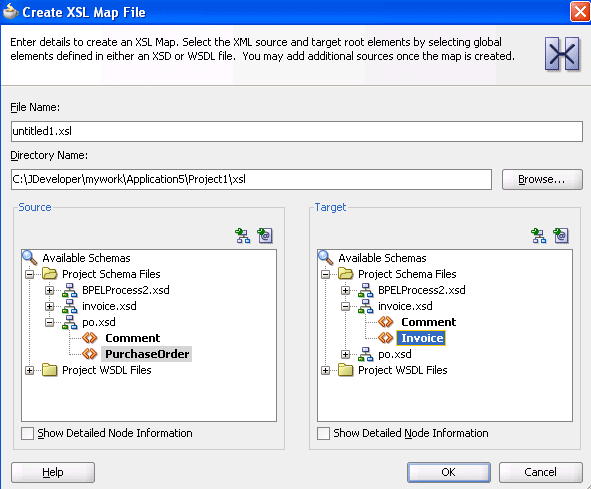
The Create XSL Map File dialog appears. This dialog enables you to create an XSL map file that maps a root element of a source schema file or Web Services Description Language (WSDL) file to a root element of a target schema file or WSDL file. Note the following details:
-
-
WSDL files that have been added to the project appear under Project WSDL Files.
-
Schema files that have been added to the project appear under Project Schema Files.
-
Schema files that are not part of the project can be imported using the Import Schema File facility. Click the Import Schema File icon (first icon to the right and above the list of schema files).
-
WSDL files that are not part of the project can be imported using the Import WSDL File facility. Click the Import WSDL File icon (second icon to the right and above the list of schema files).
-
-
-
In the File Name field, enter a name for the XSL map file.
-
Select the root element for the source and target trees. In the example in Figure 40-4, the PurchaseOrder element is selected for the source root element and the Invoice element is selected for the target root element.
-
Click OK.
A new XSL map is created, as shown in Figure 40-5.
-
Save and close the file now or begin to design your transformation. Information on using the XSLT Map Editor is provided in Introduction to the XSLT Map Editor.
-
From the Components window, drag a transform activity into your BPEL process.
-
Double-click the transform activity.
-
Specify the following information:
-
Add source variables from which to map elements by clicking the Add icon and selecting the variable and part of the variable as needed (for example, a payload schema consisting of a purchase order request).
Note:
You can select multiple input variables. The first variable defined represents the main XML input to the XSL map. Additional variables that are added here are defined in the XSL map as input parameters.
-
Add target variables to which to map elements.
-
Add the target part of the variable (for example, a payload schema consisting of an invoice) to which to map.
-
-
To the right of the Mapper File field, click the Search icon (first icon) to browse for the map file name you specified in Step 6.
-
Click Open.
-
Click OK.
The XSLT Map Editor displays your XSL map file.
-
Go to Introduction to the XSLT Map Editor for an overview of using the XSLT Map Editor.
40.2.4 How to Create an XSL Map File in Oracle Mediator
The XSLT Map Editor enables you to create an XSL file to transform data from one XML schema to another in Oracle Mediator. After you define an XSL file, you can reuse it in multiple routing rule specifications. This section provides an overview of creating a transformation map XSL file with the XSLT Map Editor.
The XSLT Map Editor is available from the Applications window in Oracle JDeveloper by clicking an XSL file or from the Mediator Editor by clicking the transformation icon, as described in the following steps. You can either create a new transformation map or update an existing one.
To launch the XSLT Map Editor from the Mediator Editor and create or update a data transformation XSL file, follow these steps.
To create an XSL map file in the Mediator Editor:
40.2.5 What You May Need to Know About Creating an XSL Map File
XSL file errors do not display during a transformation at runtime if you manually remove all existing mapping entries from an XSL file except for the basic format data. Ensure that you always specify mapping entries. For example, assume you perform the following actions:
40.2.6 What Happens at Runtime If You Pass a Payload Through Oracle Mediator Without Creating an XSL Map File
If you design a SOA composite application to pass a payload through Oracle Mediator without defining any transformation mapping or assigning any values, Oracle Mediator passes the payload through.
However, for the payload to be passed through successfully, the source and target message part names must be the same, and of the same type. Otherwise, the SOA project fails to compile. For projects that have been upgraded from 11g, the project compiles, but the target reference may fail to execute with error messages such as Input source like Null or Part not found.
40.2.7 What Happens If You Receive an Empty Namespace Tag in an Output Message
The XML representation from an XSL file may differ from that used in a scenario in which a message is passed through with a transformation being performed or in which an assign activity is used, even though the XMLs are syntactically and semantically the same. For example, if you use an Oracle Mediator service component to map an inbound payload that includes an element without a namespace to an outbound payload, you may receive an empty namespace tag in the output message.
<Country xmlns="">US</Country>
This is the correct behavior. A blank namespace, xmlns="", is automatically added.
40.3 Editing an XSLT Map in Map View
This section discusses basic functionality available in Map View. The remaining sections discuss editing in the XSLT View with notes on restrictions that might apply to Map View for the specific activity being discussed.
40.3.1 How to Perform a Value Copy by Linking Nodes
To copy the value of an attribute or leaf-element in the source to an attribute or leaf-element in the target, drag a line from the source node to the target node. A green highlighted line appears as you are dragging and dropping. When you complete the drop, a line is drawn connecting the source and target nodes.
Figure 40-10 shows the map view where the PurchaseOrder/ID source element is mapped to the Invoice/ID target element. Notice that a line connects the source and target nodes. Also, the ID element in the target tree is no longer grayed, and appears in normal font. This means that the ID element has been added to the XSLT map.
Figure 40-10 Copying a Leaf Node in Map View

Description of "Figure 40-10 Copying a Leaf Node in Map View"
40.3.2 How to Create an Empty Node in the Output Document
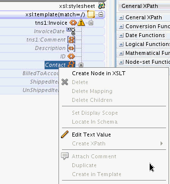
To create an empty node in the output document:
- Select the grayed node in the target pane.
- Right-click the node, and select Create Node in XSLT from the context menu.
40.3.3 How to Set a Literal Text Value for a Target Node
To set a literal text value on an output/target node:
40.3.4 How to Add an XSLT Statement
You can add XSLT statements to handle constructs such as conditional statements (if-then-else) and iterations (for-each).
40.3.4.1 To Add an XSLT Statement:
-
Right-click the target node, and select Add XSL Instruction from the context menu that appears. A submenu appears with the various XSL statements that you can add.
-
Select the desired XSL statement, such as if, choose, or for-each, from the submenu.
The xsl:text and xsl:variable XSLT statements can only be added for existing nodes.
40.3.4.2 To Add an xsl:text or xsl:variable Statement:
-
Make sure that the target node exists in the XSLT.
If the target node appears gray, right-click the target node and select Create Node in XSLT from the context menu that appears. The node no longer appears gray, and is added to the XSLT map.
-
Right-click the target node, and select Add XSL Instruction from the context menu that appears. A submenu appears with the various XSL statements that you can add.
-
Select text or variable from the submenu.
Note:
The
xsl:copy-ofstatement is not supported in Map View. It is supported in XSLT View.
You can also choose to drag and drop XSLT statements from the Components window.
40.3.4.3 To Drag and Drop an XSLT statement to a Target Node:
-
Select the XSLT Elements page from the Components Window. A list of statement categories appear.
-
Locate a supported statement, for Map View, from a category. For example, the for-each statement appears under the Flow Control category.
The Map View supports only a subset of XSLT statements. These statements are discussed individually in the sections that follow.
-
Drag the statement to the desired target node until green highlighting appears over the node, indicating that the statement can be dropped.
-
Drop the statement to insert it into the XSLT map.
The following sections enumerate the different XSLT statements that you can add using the map view:
40.3.4.4 How to Add Conditional Processing Using xsl:if
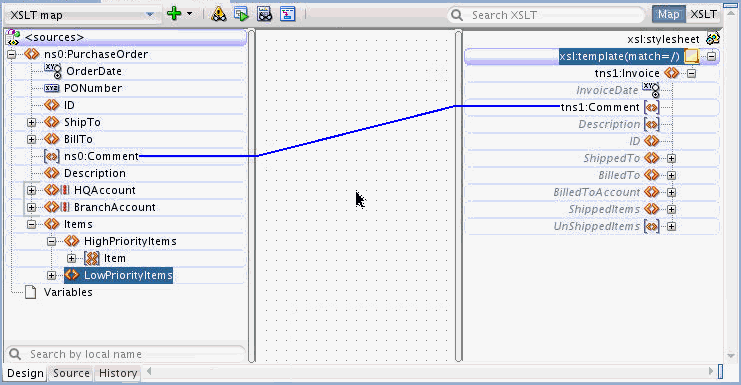
If a source and target node are optional in their respective schemas, the xsl:if statement is often used to test for the existence of the source node before creating the corresponding target node.
In Figure 40-11, the Comment node is optional for both the source and the target. The square brackets around the Comment nodes indicate that they are optional nodes.
Figure 40-11 Optional Nodes in Source and Target Trees
Description of "Figure 40-11 Optional Nodes in Source and Target Trees"
If the source Comment node does not exist in the source document at runtime, its value is empty. This creates a Comment node in the target document and sets its value to empty.
To prevent creating an empty node when the source node is not there, add an xsl:if statement above the target Comment node. The xsl:if statement tests for the existence of the source node before creating the target node.
40.3.4.4.1 To add an xsl:if statement using the context menu:
-
Right-click the target node and select Add XSL Instruction -> if from the context menu that appears. An
xsl:ifnode is added as the parent node of the target node. -
To set the condition for the
xsl:ifnode, drag and drop the source node to thexsl:ifnode.Figure 40-12 Dragging the Source Node to the xsl:if Node
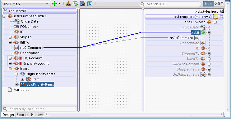
Description of "Figure 40-12 Dragging the Source Node to the xsl:if Node"
40.3.4.4.2 To add an xsl:if statement using drag and drop:
-
In the Components window, select the XSLT Elements page.
-
Expand the Flow Control section. You can click the plus sign (+) next to Flow Control to expand the section.
-
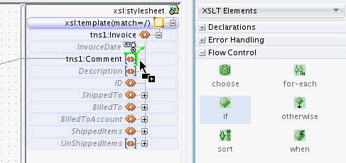
Drag the if icon to the right side of the target node until you can see the green highlighting, as shown in Figure 40-13.
-
Drop the if icon while the green highlighting is visible. An
xsl:ifnode is added as the parent node of the target node. -
To set the condition for the
xsl:ifnode, drag and drop the source node to thexsl:ifnode.
When viewed in source view, the xsl:if statement looks similar to the following:
<xsl:if test="/ns0:PurchaseOrder/ns0:Comment">
    <tns1:Comment>
       <xsl:value-of select="/ns0:PurchaseOrder/ns0:Comment"/>
    </tns1:Comment>
</xsl:if>
The preceding xsl:if statement ensures that the target node is created only if the source node exists.
40.3.4.5 How to Add Conditional Processing Using xsl:choose
The xsl:choose statement is similar to the xsl:if construct. You can use the xsl:choose XSLT statement if there are multiple conditions to evaluate.
Figure 40-14 shows the XSLT Map Editor containing sample source and target schemas. The source schema has an xsd:choice construct defined. The source schema can contain either an HQAccount or a BranchAccount node, but not both. The target schema has a BilledToAccount/AccountNumber node that must be defined.
If the HQAccount node exists, you must copy its AccountNumber to BilledToAccount/AccountNumber in the target. If the HQAccount node does not exist, you must copy the AccountNumber from the BranchAccount node. You can use the xsl:choose statement to accomplish this task.
Figure 40-14 XSLT Map Editor Containing Sample Source and Target Schemas
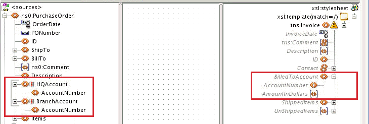
Description of "Figure 40-14 XSLT Map Editor Containing Sample Source and Target Schemas"
40.3.4.5.1 To add an xsl:choose statement using the context menu:
-
Right-click the target node and select Add XSL Instruction -> choose from the context menu that appears.
A choose statement is added as the parent node of the target node along with an
xsl:whenstatement. Figure 40-15 shows the result of adding thexsl:choosestatement to the AccountNumber node.Figure 40-15 Adding an xsl:choose Statement

Description of "Figure 40-15 Adding an xsl:choose Statement"An
xsl:choosestatement can contain multiplexsl:whenstatements followed by an optionalxsl:otherwisestatement. -
To add an
xsl:otherwisenode to the xsl:choose node, right-click xsl:choose in the target tree and select Add XSL Instruction -> otherwise from the context menu that appears.Figure 40-16 shows the result of adding the
xsl:otherwisestatement to thexsl:choosestatement. Note that the AccountNumber node is copied to each section of thexsl:choosestatement.Figure 40-16 Adding an xsl:otherwise Statement to an xsl:choose Statement
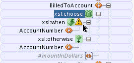
Description of "Figure 40-16 Adding an xsl:otherwise Statement to an xsl:choose Statement" -
Map the
xsl:whennode to the source node whose existence is to be tested. In our current example, you drag a line from the HQAccount node in the source to the xsl:when node in the target. -
Map the xsl:when and xsl:otherwise cases. In the current example, you drag a line from the HQAccount/AccountNumber node to the xsl:choose/xsl:when/AccountNumber node. Similarly, you drag a line from the BranchAccount/AccountNumber node to the xsl:choose/xsl:otherwise/AccountNumber node.
Figure 40-17 shows the completed
xsl:chooseconstruct.
40.3.4.5.2 To add an xsl:choose statement using drag and drop:
-
In the Components window, select the XSLT Elements page.
-
Expand the Flow Control section. You can click the plus sign (+) next to Flow Control to expand the section.
-
Drag the choose icon to the right side of the target node until you can see the green highlighting, as shown in Figure 40-18.
Figure 40-18 Dragging the choose Icon to the Target Node
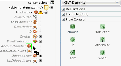
Description of "Figure 40-18 Dragging the choose Icon to the Target Node" -
Drop the choose icon while the green highlighting is visible. An
xsl:choosenode is added as the parent node of the target node. Thexsl:choosenode contains a childxsl:whennode. -
To create the otherwise clause, drag the otherwise icon from the Components Window to the left of the xsl:choose node until you can see the green highlighting, as shown in Figure 40-19.
Figure 40-19 Dragging the otherwise Icon to the xsl:choose Node
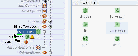
Description of "Figure 40-19 Dragging the otherwise Icon to the xsl:choose Node" -
Drop the otherwise icon while the green highlighting is visible. An
xsl:otherwisenode is added as the child node of thexsl:choosenode. -
Map the
xsl:whennode to the source node whose existence is to be tested. In our current example, you drag a line from the HQAccount node in the source to the xsl:when node in the target. -
Map the xsl:when and xsl:otherwise cases. In our current example, you drag a line from the HQAccount/AccountNumber node to the xsl:choose/xsl:when/AccountNumber node. Similarly, you drag a line from the BranchAccount/AccountNumber node to the xsl:choose/xsl:otherwise/AccountNumber node.
Figure 40-17 shows the completed
xsl:chooseconstruct.
When viewed in source view, the xsl:choose statement looks similar to the following:
<BilledToAccount>
   <xsl:choose>
     <xsl:when test="/ns0:PurchaseOrder/HQAccount">
       <AccountNumber>
         <xsl:value-of select="/ns0:PurchaseOrder/HQAccount/AccountNumber"/>
       </AccountNumber>
     </xsl:when>
     <xsl:otherwise>
       <AccountNumber>
         <xsl:value-of select="/ns0:PurchaseOrder/BranchAccount/AccountNumber"/>
       </AccountNumber>
     </xsl:otherwise>
   </xsl:choose>
</BilledToAccount>
40.3.4.6 How to Add Loops Using xsl:for-each
The xsl:for-each statement can be used to loop over a source node-set, or set of nodes, and to create output nodes for each node in the source node-set.
40.3.4.6.1 To add an xsl:for-each statement using the context menu:
-
Right-click the target node and select Add XSL Instruction -> for-each from the context menu that appears. An
xsl:for-eachstatement is added as the parent node of the target node. -
To set the source node-set to loop over, drag and drop the source node to the
xsl:for-eachstatement.Figure 40-20 shows an example of creating the
xsl:for-eachstatement. The source PurchaseOrder document contains the Item node. The Item node is a repeating node, as represented by its icon. For each Item node in the source document, an Item node is created in the target document using thexsl:for-eachstatement.Figure 40-20 Creating an xsl:for-each Statement
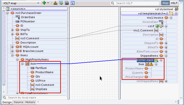
Description of "Figure 40-20 Creating an xsl:for-each Statement"
40.3.4.6.2 To add an xsl:for-each statement using drag and drop:
-
In the Components window, select the XSLT Elements page.
-
Expand the Flow Control section. You can click the plus sign (+) next to Flow Control to expand the section.
-
Drag the for-each icon to the right side of the target node until you can see the green highlighting, as shown in Figure 40-21.
Figure 40-21 Dragging the for-each Icon to the Target Node
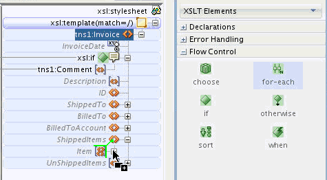
Description of "Figure 40-21 Dragging the for-each Icon to the Target Node" -
Drop the for-each icon while the green highlighting is visible. An
xsl:for-eachnode is added as the parent node of the target node. -
To set the source node-set to loop over, drag and drop the source node to the
xsl:for-eachstatement, as shown in Figure 40-20.
When viewed in the source view, the xsl:for-each statement looks similar to the following:
<ShippedItems>
  <xsl:for-each select="/ns0:PurchaseOrder/Items/HighPriorityItems/Item">
     <Item/>
  </xsl:for-each>
</ShippedItems>
Note that the Item node, created inside the xsl:for-each statement, is an empty node. You can map elements under the target Item node to set values for them.
For example, as shown in Figure 40-22, if you drag and drop Qty to Quantity, the value of the Qty element is copied to the Quantity element in the output.
The following example shows the resulting code in source view. It also shows a sample source document and output document snippet.
<ShippedItems>
  <xsl:for-each select="/ns0:PurchaseOrder/Items/HighPriorityItems/Item">
    <Item>
      <Quantity>
        <xsl:value-of select="Qty"/>
      </Quantity>
    </Item>
  </xsl:for-each>
</ShippedItems>
The following snippet shows some sample values for the source document:
<HighPriorityItems>
     <Item PartNum="000-AA">
          <Qty>20</Qty>
     </Item>
     <Item PartNum="000-AB">
          <Qty>24</Qty>
     </Item>
</HighPriorityItems>
The following snippet shows the output values corresponding to the preceding source document:
<ShippedItems>
     <Item>
          <Quantity>20</Quantity>
     </Item>
     <Item>
          <Quantity>24</Quantity>
     </Item>
</ShippedItems>
Within an xsl:for-each statement, XPath expressions are usually relative to the node selected by the xsl:for-each statement. For instance, in the preceding example Qty is relative to the current Item node /ns0:PurchaseOrder/Items/HighPriorityItems/Item:
  <xsl:for-each select="/ns0:PurchaseOrder/Items/HighPriorityItems/Item">
    <Item>
      <Quantity>
        <xsl:value-of select="Qty"/>
      </Quantity>
    </Item>
  </xsl:for-each>
Using absolute paths within the xsl:for-each statement can result in unintended results. For example, if were to use absolute path in the preceding example instead of relative path, the code looks as follows:
<ShippedItems>
 <xsl:for-each select="/ns0:PurchaseOrder/Items/HighPriorityItems/Item">
   <Item>
     <Quantity>
       <xsl:value-of
              select="/ns0:PurchaseOrder/Items/HighPriorityItems/Item/Qty"/>
     </Quantity>
   </Item>
 </xsl:for-each>
</ShippedItems>
The resultant output document looks like the following:
<ShippedItems>
  <Item>
    <Quantity>20</Quantity>
  </Item>
  <Item>
    <Quantity>20</Quantity>       <!-- repeating incorrect value! -->
  </Item>
</ShippedItems>
The absolute path always selects the first Qty element in the Item node-set and you see a repeating value placed into each output Item element.
The XSLT Map Editor creates relative paths when mapping nodes under a for-each statement, if possible. It is recommended that you create the xsl:for-each statement before mapping the nodes that appear under the for-each. If you map nodes such as Quantity before adding the for-each, the editor shows a warning and attempts to refactor the absolute XPath expressions to relative path expressions when you map the node-set to the for-each.
Note:
-
Executing an auto map automatically inserts the
xsl:for-eachstatement, where required. -
Ensure that your design does not include infinite loops. Infinite loops can result in errors similar to the following during deployment and invocation of your application:
ORAMED-04001:
. . .
oracle.tip.mediator.service.BaseActionHandler requestProcess
SEVERE:
failed reference BPELProcess1.bpelprocess1_client operation =  process
40.3.4.7 How to Add xsl:sort for an xsl:for-each Statement
The xsl:sort statement can be added to an xsl:for-each statement to specify a field based on which sorting is performed. The xsl:sort instruction causes xsl:for-each to loop over the defined node-set in a particular order.
40.3.4.7.1 To add an xsl:sort statement using the context menu:
-
Right-click the xsl:for-each node and select Add XSL Instruction -> sort from the context menu that appears.
The Set Attributes dialog appears.
-
Optionally specify attributes for the
xsl:sortstatement. Click OK.The Set Attributes dialog enables you to set attributes for the
xsl:sortstatement. Attributes control the way in which the sort is executed. For example, if you select the 'order' Attribute, you can then select ascending or descending for the sort order. Select the attributes desired for the sort.Note:
The default values for attributes are pre-selected in the Set Attributes dialog. These values are used in the absence of any selected attribute.
For instance, the default for sort order is ascending. You do not have to explicitly select 'order' Attribute to turn on ascending order.
The
xsl:sortstatement is added just below thexsl:for-eachstatement and before any other nodes under the for-each. -
To set the element to sort with, drag and drop a node from under the source node-set to the xsl:sort node. For instance, to sort on USPrice, drag the USPrice node from under the node-set element Item to the xsl:sort node, as shown in Figure 40-23.
Figure 40-23 Connecting the Source Node-Set to the xsl:sort Node

Description of "Figure 40-23 Connecting the Source Node-Set to the xsl:sort Node"
40.3.4.7.2 To add an xsl:sort statement using drag and drop:
-
In the Components window, select the XSLT Elements page.
-
Expand the Flow Control section. You can click the plus sign (+) next to Flow Control to expand the section.
-
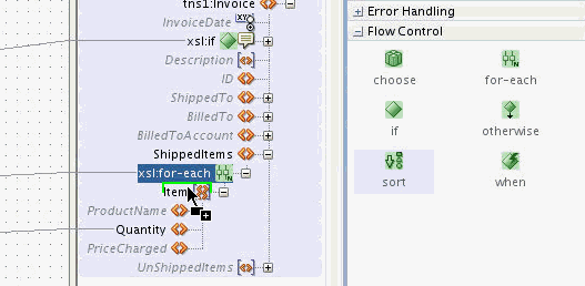
Drag the sort icon to the top of the element below the for-each node until you can see the green highlighting, as shown in Figure 40-24.
-
Drop the sort icon while the green highlighting is visible. An
xsl:sortnode is added as the sibling node of the highlighted node. In the example shown in Figure 40-24, thexsl:sortnode is added as a sibling of the Item element. -
To set the element to sort with, drag and drop a node from under the source node-set to the xsl:sort node. For instance, to sort on USPrice, drag the USPrice node from under the node-set element Item to the xsl:sort node, as shown in Figure 40-23.
When viewed in the source view, the xsl:sort statement looks similar to the following:
<xsl:for-each select="/ns0:PurchaseOrder/Items/HighPriorityItems/Item">
  <xsl:sort select="USPrice"/>
  <Item>
    <Quantity>
      <xsl:value-of select="Qty"/>
    </Quantity>
  </Item>
</xsl:for-each>
40.3.4.8 How to Duplicate XSLT Instructions
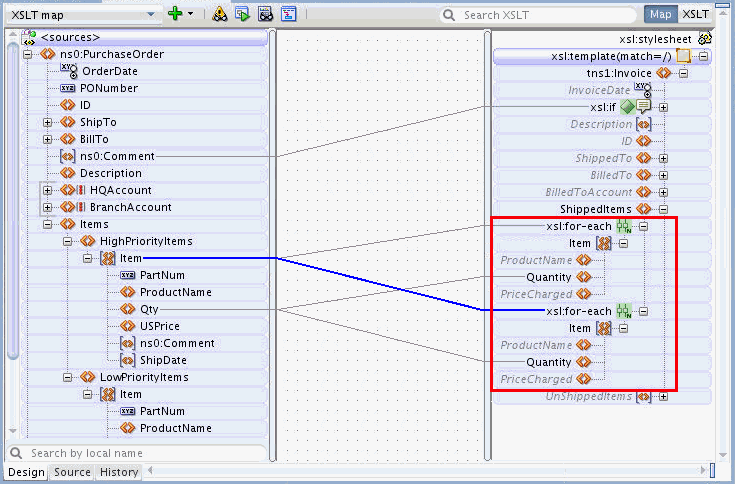
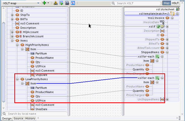
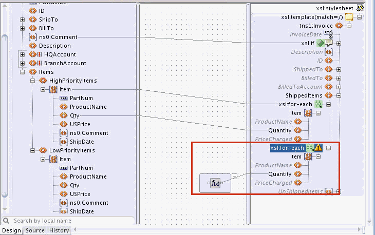
Sometimes, you must duplicate XSLT instructions in the target tree. For example, you may create two for-each statements next to one another to loop over two node-sets in the source document, or possibly to loop over the same node-set twice.
Other XSLT instructions, such as xsl:if and xsl:sort, can also be duplicated. This section illustrates creating duplicate instructions using the xsl:for-each statement. The same process applies to other XSLT instructions.
To duplicate an xsl:for-each statement:
40.3.4.8.1 Example: Modifying the Mapping by Changing the XPath Expression
In this example, you modify the duplicate xsl:for-each statement to loop over the Item nodes under the LowPriorityItems node in the source document. There are several ways to modify the mappings. The following example discusses one way to modify the mappings.
If you edit the XPath expression associated with a for-each statement, all relative mappings under the for-each are automatically updated. Use the following steps to modify the XPath expression associated with the duplicate for-each statement:
-
To edit the XPath expression, double-click the line connected to the second for-each. This is the blue line in Figure 40-25.
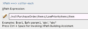
The Edit XPath dialog appears. The XPath Expression field displays the XPath expression corresponding to the map.
-
Change HighPriorityItems to LowPriorityItems in the XPath Expression. Click OK.
The
xsl:for-eachstatement and all its children now reference theLowPriorityItems/Itemnode-set.
40.3.4.8.2 Example: Modifying the Mapping by Deleting and Re-Creating It
To modify the mapping for the for-each statement, you can also choose to remove the mapping and re-create it. The following steps illustrate the process to modify the mappings for the duplicate for-each statement:
-
Right-click the duplicate xsl:for-each node and select Delete Mapping from the context menu that appears.
The Refactor XPaths dialog appears asking if you want to refactor the XPath expressions under the for-each statement.
-
Click No to refactoring. This keeps the relative paths, as you plan to apply these relative paths to a different loop. After you click No, the lines underneath the for-each statement become temporarily disconnected from the source tree.
In the preceding figure, the relative XPath expression assigned to the
Quantityfield isQty.Without the XPath expression on the for-each statement, the relative path has noItemnode to be relative to, and consequently, no reference is found in the source tree.Note:
In general, XPath expressions that cannot be resolved to nodes in the source tree are represented in the center panel. This can sometimes indicate an issue, as in the preceding case. There is a relative path that cannot be resolved because of a missing for-each expression above it.
An XPath expression can also be represented in the center pane if the expression is too complex to determine a source reference node at design time.
-
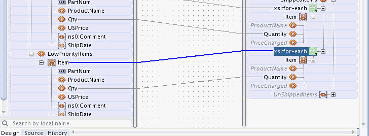
Drag and drop a line from the LowPriorityItems/Item node in the source tree to the duplicate xsl:for-each statement.
The mapping to the
Quantityfield automatically reconnects to theQtyfield under theLowPriorityItems/Itemnode, as shown in the following figure.
40.3.5 How to Duplicate an Element
In order to duplicate a target node in Map view, the node must have been defined as a repeating node in the target schema. For certain cases, you can create repeating nodes using for-each loops, as discussed in the preceding section. In other cases, you may need to create several independent instances of a node and map data to them through different areas of the source document.
To duplicate a repeating target node:
40.3.6 How to Delete an Element or Attribute
To delete an element or attribute from the current XSLT Map, the element or attribute must first exist in the XSLT. Nodes in the target tree that are not grayed, and not in italics, are nodes that exist in the XSLT. Nodes that are grayed, and in italics, are not part of the XSLT. Such grayed nodes represent candidate elements and attributes from the target schema, and cannot be deleted from the display.
To delete a target node that exists in the XSLT, do one of the following:
-
Click the target node to select it. Press the Delete key.
-
Right-click the target node and select Delete from the context menu that appears.
The node is removed from the XSLT and any mapping to the node is also removed. The deleted node is not removed from the display. The deleted node becomes gray and italicized indicating that it is now just a possible target node from the target schema, and is no longer part of the XSLT. However, if the deleted node was a duplicate node, or was in a position non-compliant with the target schema, then the node is removed from the display.
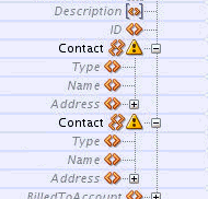
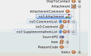
The following figure shows two comment nodes that are part of the XSLT map.
If you right-click the second Comment node and select Delete from the context menu, the duplicate node is removed from the XSLT and the display, as shown in the figure below.
Next, you right-click and remove the remaining Comment node. The node is not removed from the display, but is removed from the XSLT and its appearance changes to gray and italicized, as shown in the following figure.
40.3.7 How to Remove Mappings from an Element or Attribute
To remove the mapping to any target node, right-click the node in the target tree and select Delete Mapping from the context menu that appears. Alternatively, you can select the line representing the mapping, and press the Delete key.
When you remove a mapping in Map View, the node that was mapped to is not removed from the XSLT. To remove the node, right-click and select Delete from the context menu that appears. If only the mappings are removed and the node is not, the XSLT generates an empty node when executed.
40.4 Editing an XSLT Map in XSLT View
This section discusses basic editing using the XSLT pane in XSLT View. The following list includes the major differences between editing in XSLT View and editing in Map View:
-
XSLT View does not provide a merged view of the XSLT nodes and the target schema. The right target pane is divided into two panes. The top pane is called the XSLT pane and the lower pane is called the target pane. If no target schema is defined, then the lower pane is not shown.
-
In order to map to target nodes, these nodes must be explicitly added to the XSLT pane before they can be mapped. The editor provides several ways to do this. These are discussed in the subsequent sections.
-
The complete range of XSLT 1.0 instructions is available in XSLT View. These instructions can be added anywhere within the XSLT panel, so long as their position is consistent with the XSLT specification.
-
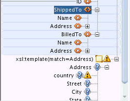
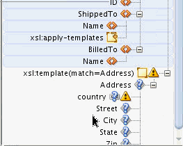
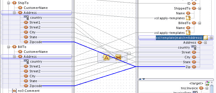
A number of advanced features are available in XSLT View, such as template rules (matched templates), named templates, import/include, and so on. These advanced features are discussed later in this chapter.
40.4.1 How to Add a Target Element or Attribute Before Mapping
Before mapping to target elements and attributes, the element or attribute must be explicitly added to the XSLT pane. This section contains the following topics:
40.4.1.1 How to Add Elements and Attributes from the Target Schema
If the target schema is present, you can add elements and attributes from the target tree to the XSLT pane.
You can either use the context menu for an XSLT element or attribute to add a related element/attribute, or drag and drop the desired element/attribute from the target tree to the XSLT tree.
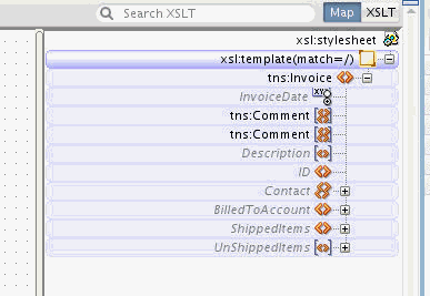
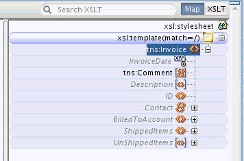
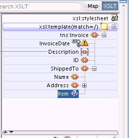
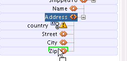
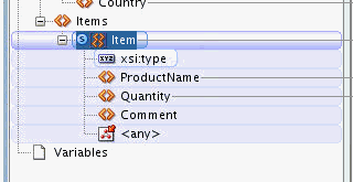
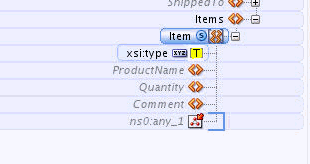
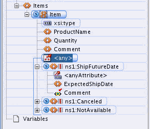
If elements are placed in positions that are inconsistent with the target schema, or if the editor cannot yet determine if the element is valid at the location due to an incomplete XSLT map, then a question mark is shown over the element's icon. The following figure shows an XSLT tree where the Item element is marked with a question mark.
40.4.1.1.1 To add elements and attributes when target schema is present:
-
Right-click the element, in the XSLT pane, that is to contain the child element(s) or attribute(s). A context menu appears.
Note:
This action can also be executed from Map View if the selected node exists in the XSLT.
In Map View, you can also add an empty XSLT node by choosing Create Node in XSLT. See How to Create an Empty Node in the Output Document for more details.
-
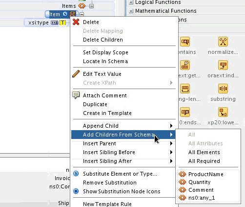
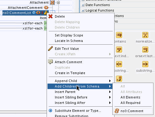
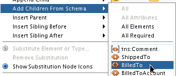
Select Add Children From Schema. A submenu appears with choices that are consistent with the target schema. Figure 40-28 shows the Add Children From Schema submenu.
Figure 40-28 Selecting Child Elements/Attributes to Add
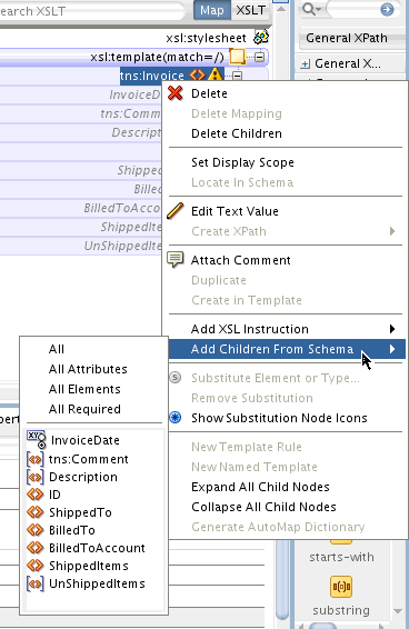
Description of "Figure 40-28 Selecting Child Elements/Attributes to Add" -
Select the element name or attribute name to add. To add all child elements or attributes, select All Elements or All Attributes. Select All Required to add all required child elements or attributes.
40.4.1.1.2 To drag and drop elements and attributes from the target schema tree:
-
To insert an element as a child of an existing element:
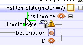
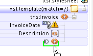
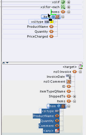
Drag the target element, or a selected range of elements, from the target pane to the left of the desired element in the XSLT tree. A green highlight appears to indicate that the element is being inserted as a child. Upon drop, the child is appended to the list of children.
If the green highlight does not appear at a particular position, then it means it is invalid to insert the element at that position.
-
To insert an element as a sibling after an existing element:
Drag the target element, or a selected range of elements, from the target pane to the bottom of the existing element in the XSLT tree. A green highlight appears to indicate that the element is being inserted as a sibling. Upon drop, the sibling is appended after the existing element.
-
To insert an element as a sibling before an existing element:
Drag the target element, or a selected range of elements, from the target pane to the top of the existing element in the XSLT tree. A green highlight appears to indicate that the element is being inserted as a sibling. Upon drop, the sibling is appended before the existing element.
-
To insert an element as a parent of an existing element:
Drag the target element, or a selected range of elements, from the target pane to the right of the existing element in the XSLT tree. A green highlight appears to indicate that the element is being inserted as a parent. Upon drop, the element is inserted as the parent of the existing element.
40.4.1.2 How to Add Literal Elements and Attributes When No Target Schema Is Present
This section applies to both XSLT and Map views.
40.4.1.2.1 To add a literal element when there is no target schema:
-
Right-click an element in the XSLT pane. The context menu for the element appears.
-
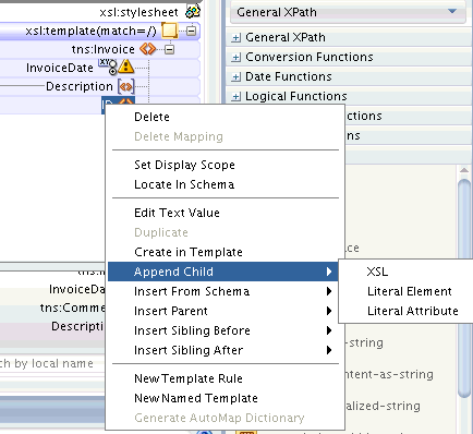
Select the relative position of the new literal element relative to the existing element. You can create the literal element as the child, sibling, or parent of the existing element. Figure 40-29 shows the available options (Append Child, Insert Parent, Insert Sibling Before, Insert Sibling After).
Figure 40-29 Adding a Literal Element to the XSLT Pane
Description of "Figure 40-29 Adding a Literal Element to the XSLT Pane" -
Select Literal Element from the submenu. The Define Element dialog appears.
-
Under Local Name, enter a name for the literal element. You can optionally specify a namespace for the element.
-
Click OK to close the Define Element dialog.
40.4.1.2.2 To add a literal attribute when there is no target schema:
-
Right-click an existing literal element in the XSLT pane. The context menu for the literal element appears.
-
Select Append Child > Literal Attribute. The Define Element dialog appears.
-
Under Local Name, enter a name for the literal attribute. You can optionally specify a namespace for the attribute.
-
Click OK to close the Define Attribute dialog.
40.4.1.3 How to Create an Empty Node in the Output Document
When you use the methods discussed under the preceding sections (How to Add Elements and Attributes from the Target Schema and How to Add Literal Elements and Attributes When No Target Schema Is Present) to add nodes to the XSLT pane, these nodes are created as empty nodes unless you map them to source nodes. Also, when you add a complex node to the XSLT pane, all required nodes under the complex node are created automatically.
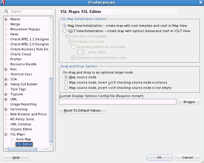
You can also set the XSL Map Initialization Options in the XSL Maps: XSL Editor preferences page to generate empty nodes when a map is created. See How to Set the XSL Editor Preferences for more information.
40.4.2 How to Perform a Value Copy by Linking Nodes
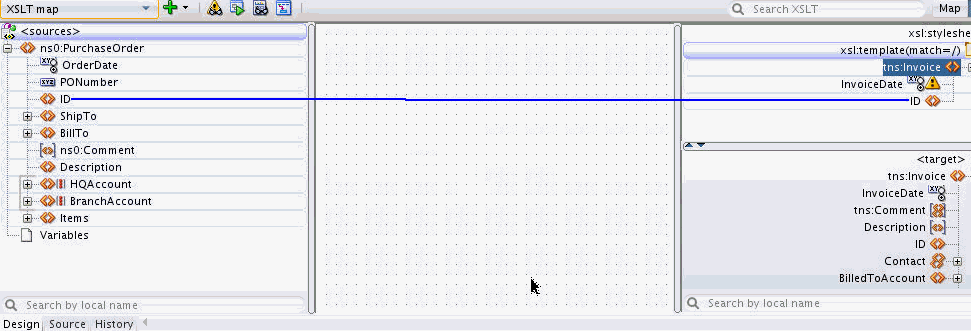
To copy the value of an attribute or leaf-element in the source to an attribute or leaf-element in the XSLT pane, drag a line from the source node to the XSLT node. A green highlighted line appears as you are dragging and dropping. When you complete the drop, a line is drawn connecting the source and target nodes.
Figure 40-30 shows the XSLT view where the PurchaseOrder/ID source element is mapped to the Invoice/ID XSLT element. A line connects the source and XSLT node.
40.4.3 How to Insert an xsl:valueof Statement
When you map a source element to an XSLT element, as described in the preceding section, an implicit xsl:valueof statement is created in the XSLT.
In XSLT View, you can explicitly create multiple xsl:valueof elements for an XSLT element. The resultant value of the XSLT element is the concatenation of the individual xsl:valueof values.
To create an xsl:valueof element for an XSLT element:
If an xsl:value-of element is added to a literal element that has no mapping, the xsl:value-of statement appears under the literal element until it is mapped. After you map the xsl:value-of element, the editor hides the xsl:value-of statement under the literal element and shows only the line indicating the mapping.
If you add multiple xsl:value-of statements to the literal element, then all xsl:value-of statements are explicitly shown under the literal element, and mapping lines can be separately drawn to each xsl:value-of element.
40.4.4 How to Set a Literal Text Value for an XSLT Node
To set a literal text value for an XSLT node:
40.4.5 How to Set a Literal Text Value Using an xsl:text Instruction
To set the value for a literal element using the xsl:text instruction:
40.4.6 How to Add XSLT Statements
This procedure applies to XSLT View only. XSLT statements can be added using the Components window or context menu.
40.4.6.1 To add an XSLT element using the context menu:
-
Right-click an element in the XSLT pane. The context menu for the element appears.
-
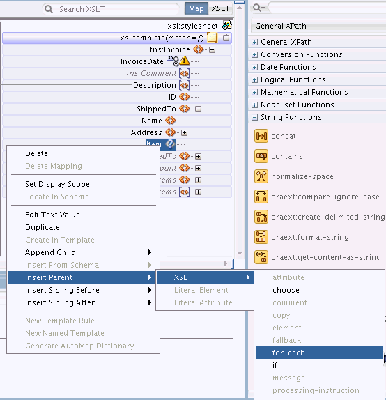
Select the relative position of the new element relative to the existing element. You can create the literal element as the child, sibling, or parent of the existing element. The available options are Append Child, Insert Parent, Insert Sibling Before, and Insert Sibling After.
-
Select XSL from the submenu. A list of available XSLT elements valid for the position is displayed. Figure 40-31 shows a sample XSL selection.
-
Select the desired XSLT element.
Depending on the element selected, a dialog may prompt you for attribute values. If so, then enter the attribute values, and click OK.
-
The XSLT element gets added to the tree.
The attributes of the added element are not explicitly shown in the XSLT tree. Hover your mouse over the element to see its attributes in the tooltip text. Alternatively, select the XSLT element to view and edit the element properties in the Properties window.
40.4.6.2 To add XSLT elements from the Components window:
-
Make sure that the Components window is visible. The default location is the top right hand corner of Oracle JDeveloper.
-
If the Components window is not visible, select Components from the Window menu.
-
Select the XSLT Elements page.
-
Select the desired section under XSLT Elements. Drag the desired XSLT element to the XSLT pane.
-
To insert the XSLT element as a child of an existing element:
Drag the XSLT element from the Components window to the left of the existing element in the XSLT tree. A green highlight appears to indicate that the XSLT element is being inserted as a child. Upon drop, the XSLT element is appended to the end of any existing children.
If the green highlight does not appear at a particular position, then it means it is invalid to insert the element at that position.
-
To insert the XSLT element as a sibling after an existing element:
Drag the XSLT element from the Components window to the bottom of the existing element in the XSLT tree. A green highlight appears to indicate that the XSLT element is being inserted as a sibling. Upon drop, the XSLT element is appended after the existing element.
-
To insert the XSLT element as a sibling before an existing element:
Drag the XSLT element from the Components window to the top of the existing element in the XSLT tree. A green highlight appears to indicate that the XSLT element is being inserted as a sibling. Upon drop, the XSLT element is appended before the existing element.
-
To insert the XSLT element as a parent of an existing element:
Drag the XSLT element from the Components window to the right of the existing element in the XSLT tree. A green highlight appears to indicate that the XSLT element is being inserted as a parent. Upon drop, the XSLT element is added as the parent of the existing element.
Depending on the XSLT element selected, a dialog may prompt you for attribute values. If so, then enter the attribute values, and click OK.
-
-
The XSLT element gets added to the tree.
The attributes of the added element are not explicitly shown in the XSLT tree. Hover your mouse over the element to see its attributes in the tooltip text. Alternatively, select the XSLT element to view and edit the element properties in the Properties window.
40.4.7 How to Set the Value of an XSLT Expression Attribute
Many XSLT instructions contain special attributes that are interpreted as XPath expressions. These expression attributes are generally named select or test. For example, the xsl:for-each element contains a select attribute and the xsl:if element contains the test attribute.
Such attributes can be defined by XPath expressions. You can set the values for these attributes using drag and drop to the XSLT element in the XSLT pane (in XSLT View) or target pane (in Map View).
To set the value of an XSLT expression attribute using drag and drop from the source tree, drag a line from the desired node in the source tree to the desired XSLT element in the XSLT pane. A line appears connecting the source tree node to the XSLT element.
The appropriate expression attribute is inserted for the XSLT instruction in the source view. For example:
<xsl:if test="/ns0:PurchaseOrder/BillTo/Address/@country">
The preceding example code is formed by dragging the country attribute in the source schema to the xsl:if statement in the XSLT tree. The code causes the if condition to test for the presence of the country attribute in the source schema.
40.4.8 How to Duplicate an Element
To duplicate a literal element in the XSLT pane that is defined as a repeating node in the target schema, use the instructions under How to Duplicate an Element. The instructions are same as those for the Map View.
If no target schema is defined, you can duplicate any node in XSLT View, except the root node.
If a node needs to be duplicated, but the node is not defined as a repeating node in the target schema, you can create a duplicate node by explicitly creating a literal element as follows:
To duplicate a literal element that is not defined as a repeating node in the target schema:
- In the XSLT pane, right-click the element to be duplicated. The context menu appears.
- Select Insert Sibling After -> Literal Element from the context menu. The Define Element dialog appears.
- Enter the element name and namespace of the node to be duplicated. Click OK.
40.4.9 How to Delete an Element or Attribute
This feature is available in both the XSLT and Map views. When using Map View, the action is to be performed in the target pane.
To delete a target node that exists in the XSLT, do one of the following:
-
Right-click the node in the XSLT pane. Select Delete from the context menu that appears.
-
Click the node in the XSLT pane to select it. Press the Delete key.
The node is removed from the XSLT pane together with any mappings to the node.
40.4.10 How to Move an Element
You can move an element by dragging it from one position and dropping it to another position in the XSLT pane. The element can be moved to become a sibling, parent, or child of another element. You cannot move an element in Map View.
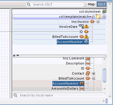
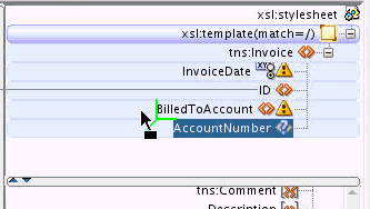
In Figure 40-32, the AccountNumber element is at an incorrect location in the XSLT pane. To make it consistent with the target schema, you must move the AccountNumber element under the BilledToAccount element.
Drag the AccountNumber node in the XSLT pane to the left of the BilledToAccount node until the green highlight appears, as shown in Figure 40-33. The green highlight indicates that the AccountNumber element is dropped as a child of BilledToAccount.
Figure 40-33 Dragging the AccountNumber Node
Description of "Figure 40-33 Dragging the AccountNumber Node"
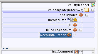
Drop the element while the green highlight is visible. The AccountNumber node is repositioned under the BilledToAccount node, as shown in Figure 40-34.
Figure 40-34 Repositioned AccountNumber Node
Description of "Figure 40-34 Repositioned AccountNumber Node"
40.4.11 How to Remove Mappings from an Element or Attribute
To remove the mapping to any XSLT node, right-click the node and select Delete Mapping from the context menu. Alternatively, you can select the line representing the mapping, and press the Delete key. You can use the preceding methods in both the Map and XSLT views.
40.5 Using XPath Expressions
How to Perform a Value Copy by Linking Nodes and How to Perform a Value Copy by Linking Nodes discussed how to use the drag and drop action to create a mapping between a source and target element or attribute. The drag and drop action creates an XPath expression in the XSLT that references specific nodes in the source document.
For example, the following XSLT code is generated by mapping a source element to a target element:
<ID>
 <xsl:value-of select="/ns0:PurchaseOrder/ID"/>
</ID>
The preceding code contains an xsl:value-of statement. The select attribute for this statement contains an XPath expression (/ns0:PurchaseOrder/ID)that references the source node being mapped.
This XPath expression represents a location path expression. XPath expressions can also be complex and include XPath functions and operators.
For example, the following code concatenates the value of the source element /PurchaseOrder/ID to the value of the attribute, /PurchaseOrder/@PONumber. It then assigns the result to the target element, <ID>.
<ID>
 <xsl:value-of select="concat(/ns0:PurchaseOrder/ID,/ns0:PurchaseOrder/@PONumber )"/>
</ID>
In the preceding code, the value in the select attribute is the XPath expression. The XPath expression uses the concat function to concatenate two source node values.
The XSLT Map Editor provides a number of ways to enter more complex XPath expressions than those that are created by simple drag and drop actions. The following methods for creating XPath expressions are available in both Map and XSLT View.
40.5.1 How to Modify an Existing Source to Target Mapping
You can modify the XPath expression for a mapping created from a drag and drop action between a source and target node.
40.5.1.1 To edit an XPath expression using the Edit XPath dialog
-
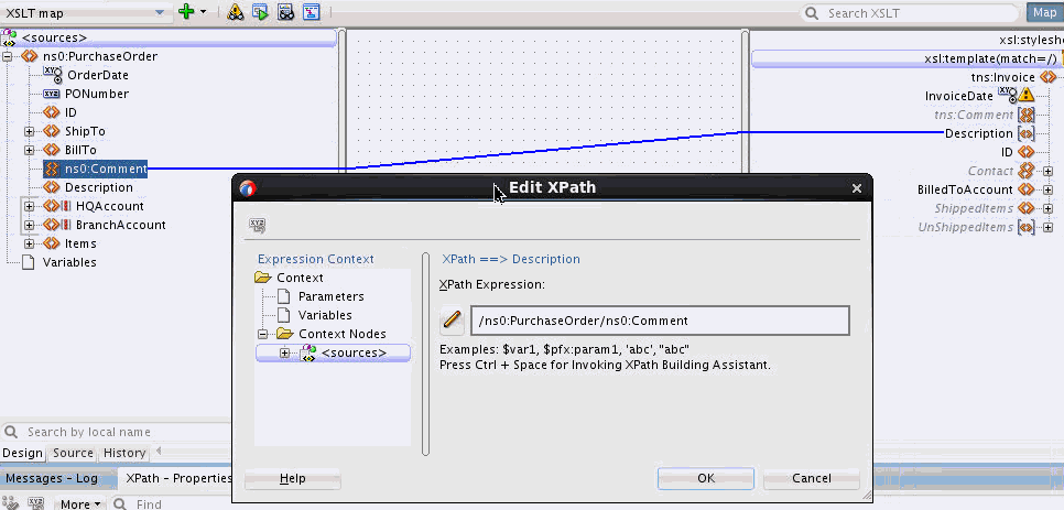
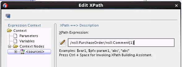
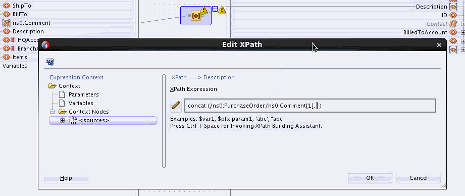
Double-click the line representing the source to target mapping. The Edit XPath dialog appears.
-
Edit the XPath Expression, as needed.
For example, if you want the Description field to contain the first Comment that occurs in the source, you add a predicate to the expression with the index of the first Comment.
Click Help if you need more information on editing the XPath expression.
-
Click OK in the Edit XPath dialog.
40.5.1.2 To edit an existing XPath expression using the Properties window
-
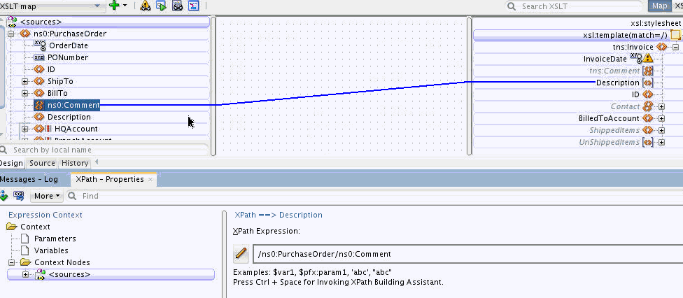
If the Properties window is not visible, select Window > Properties from the Oracle JDeveloper menu bar.
The default location of the Properties window is below the XSLT Map Editor.
-
Click to select the line representing the source to target mapping. The Properties window shows the XPath expression corresponding to the selected map line.
-
Edit the XPath Expression, as needed.
For example, if you want the Description field to contain the first Comment that occurs in the source, you add a predicate to the expression with the index of the first Comment.
Click the Help icon in the Properties window, if you need more information on editing the XPath expression.
-
To update the XSLT with the changes, click the Apply Changes icon in the upper left corner of the Properties window. Alternatively, click anywhere in the XSLT Map Editor.
40.5.1.3 How to Add an XPath Function to an Existing XPath Expression
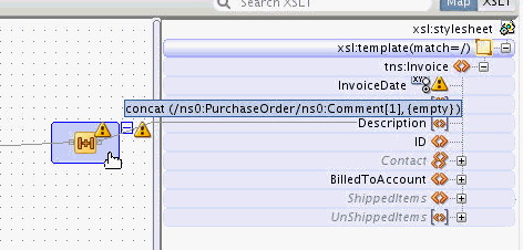
You can drag and drop a function onto an existing source to target mapping. When you drop a function on a map, the existing location path expression is used to populate the first parameter of the function that is dropped.
In the following steps, you change the expression you edited in the preceding section (How to Modify an Existing Source to Target Mapping). You use the concat function to concatenate the first Comment in the source with the Description in the source.
To add an XPath function to an existing XPath expression
40.5.2 How to Modify an Existing Function XPath Expression in the Canvas Pane
XPath functions are shown in the canvas panel and can be edited in several ways. Continuing our example from the previous section (How to Add an XPath Function to an Existing XPath Expression), you set the value of the second parameter of the concat function in several ways.
40.5.2.1 To set a function parameter using drag and drop:
-
Drag a line from the Description element in the source tree to the left side of the concat function icon in the canvas pane. A pop-up panel appears with connectors for each possible parameter in the function.
-
Drop the line on the desired connector. In the preceding figure, you drop the line on the second connector, which represents the second required parameter. You can also choose to drop the line on the third optional parameter, and fill in the second parameter value later.
The parameter is added to the function. The warning icon disappears after all required parameters have been added.
40.5.2.2 To delete a function parameter:
To delete a function parameter, select the line representing the input to the function parameter and press the Delete key. Alternatively, you can right-click the line and select Delete from the context menu.
40.5.2.3 How to Edit a Function as a Full XPath Expression
You can edit an XPath function as a textual XPath Expression using the XPath Edit dialog or the XPath Edit panel in the Properties Window.
40.5.2.3.1 To edit a function as a textual XPath expression using the XPath Edit dialog:
-
Double-click the expression folder in the canvas pane, in the area bordering the function icon. The Edit XPath dialog appears.
If you double-click the center icon instead, it brings up the Edit Function dialog.
-
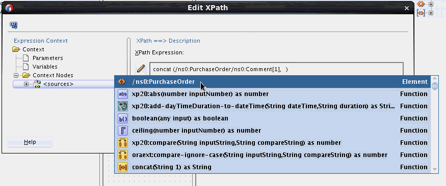
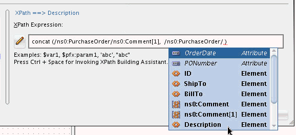
Edit the XPath Expression, as desired. To add the XPath location path for the Description node, for example, place the cursor after the first parameter. Press Ctrl + Space and double-click /ns0:PurchaseOrder to select it.
/ns0:PurchaseOrderis inserted in the expression and the drop-down menu is populated with the possible children of the/ns0:PurchaseOrdernode. -
Double-click the Description entry to select it. You can also put the mouse cursor on an entry, and press the Enter key to select it.
-
Click OK in the Edit XPath dialog.
40.5.2.3.2 To edit a function as a textual XPath expression using the Properties Window:
-
If the Properties window is not visible, select Window > Properties from the Oracle JDeveloper menu bar.
The default location of the Properties window is below the XSLT Map Editor.
-
Click the expression folder in the canvas pane, in the area bordering the function icon. The full XPath Expression for the function appears in the right pane of the Properties window.
-
Edit the XPath Expression, as desired. You can also refer to Steps 2 to 3 in the preceding procedure.
-
To update the XSLT with the changes, click the Apply Changes icon in the upper left corner of the Properties window. Alternatively, click anywhere in the XSLT Map Editor.
40.5.2.4 How to Edit Individual Function Parameters
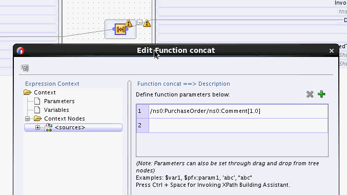
The XSLT Map Editor can parse a function into its corresponding parameters, so that the XPath for each parameter can be edited in a separate XPath Expression field.
40.5.2.4.1 To edit the parameters of a function using the Edit Function dialog:
-
Double-click the function icon in the canvas pane. The Edit Function dialog appears.
Make sure you double-click the center function icon. Double-clicking the area bordering the function icon brings up the Edit XPath dialog.
-
Edit the function parameters individually, as desired. Optionally click Help for more information about editing the parameters.
-
Click the Add icon, represented by the green plus sign (+), to optionally add a new parameter.
-
Click OK after you finish editing the parameters.
40.5.2.4.2 To edit the parameters of a function using the Properties window:
-
If the Properties window is not visible, select Window > Properties from the Oracle JDeveloper menu bar.
The default location of the Properties window is below the XSLT Map Editor.
-
Click the center area of the function icon in the canvas pane. The function parameters appear in the right pane of the Properties window.
-
Edit the function parameters, as desired. Optionally click the Help icon for more information about editing the parameters.
-
Click the Add icon, represented by the green plus sign (+), to optionally add a new parameter.
-
To update the XSLT with the changes, click the Apply Changes icon in the upper left corner of the Properties window. Alternatively, click anywhere in the XSLT Map Editor.
40.5.3 How to Create a New Function in the Canvas Pane
There are several ways to create a new function in the XSLT canvas pane. These are described in the sections that follow.
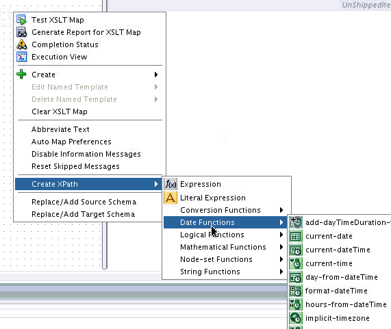
40.5.3.1 To create an XPath Function using the canvas context menu
-
Right-click a blank area in the center canvas pane. Select Create XPath from the context menu that appears.
-
Select the desired function from the Create XPath submenu. For example, select the current-date function from the Date Functions category.
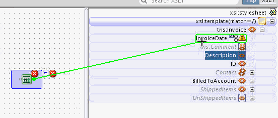
An Information dialog may appear, prompting you to connect the function to a target node. Click OK.
The function icon appears on the canvas pane.
-
Map the function to a target node by dragging a line from the function to the target node.
-
If the function requires parameters, edit the parameters using one of the methods discussed in How to Modify an Existing Function XPath Expression in the Canvas Pane.
40.5.3.2 To create an XPath function using the Components window
-
If the Components window is not visible, select Window > Components from the Oracle JDeveloper menu bar.
-
In the Components window, select General XPath or Advanced XPath. Select a category of functions, for example, String Functions.
-
Drag the desired function from the Components window to the center canvas pane of the XSLT Map Editor.
-
Map the function to a target node by dragging a line from the function to the target node.
-
If the function requires parameters, edit the parameters using one of the methods discussed in How to Modify an Existing Function XPath Expression in the Canvas Pane.
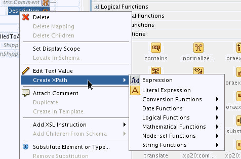
40.5.3.3 To create an XPath function using the target tree context menu
-
Right-click the target tree node (Map View) or the XSLT tree node (XSLT View) to which the XPath function needs to be assigned. The context menu appears.
-
Select Create XPath. Select the desired XPath function from the submenu that appears.
The function is created in the canvas pane and linked to the target/XSLT node for which it was created.
-
If the function requires parameters, edit the parameters using one of the methods discussed in How to Modify an Existing Function XPath Expression in the Canvas Pane.
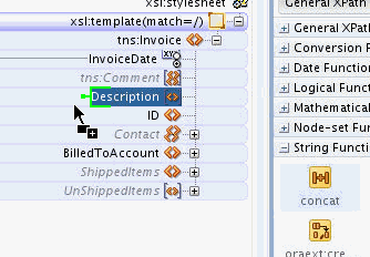
40.5.3.4 To create an XPath function by dragging it to the target tree
-
If the Components window is not visible, select Window > Components from the Oracle JDeveloper menu bar.
-
In the Components window, select General XPath or Advanced XPath. Select a category of functions, for example, String Functions.
-
Drag the desired function from the Components window to the target tree node (Map View), or XSLT tree node (XSLT View), to which the function is to be assigned. A green highlight appears to the left of the target/XSLT tree node.
-
Drop the function while the green highlight is visible.
The function is created in the canvas pane and linked to the target/XSLT node where the function was dropped.
-
If the function requires parameters, edit the parameters using one of the methods discussed in How to Modify an Existing Function XPath Expression in the Canvas Pane.
40.5.4 How to Chain Functions Together
To chain one function to another:
Complex expressions can be built by chaining functions (that is, mapping the output of one function to the input of another). For example, to remove all leading and trailing spaces from the output of the concat function, perform the following steps:
- Drag the left-trim and right-trim functions into the border area of the concat function.
- Chain them as shown in Figure 40-35 by dragging lines from the output side of one function to the input side of the next function.
Chaining can also be performed by dragging and dropping a function onto a connecting link.
40.5.5 How to Remove an XPath Expression
To remove an XPath Expression:
- Select the XPath expression/function icon in the Canvas pane.
- Right-click the icon and select Delete from the context menu.
40.5.6 How to Import User-Defined Functions
You can create and import a user-defined Java function if you have complex functionality that cannot be performed in XSLT or with XPath expressions.
Follow these steps to create and use your own functions. External, user-defined functions can be necessary when logic is too complex to perform within the XSL map.
To import user-defined functions:
40.6 Using Auto Map to Map Complex Nodes
When you map a non-leaf source element to a non-leaf target element, the Auto Map feature assists you by automatically matching the child source elements to their corresponding target elements. Auto Map looks at the element names, types, and paths to come up with the correct mappings. Auto map can also insert xsl:if statements for optional nodes, depending on your preferences.
The Auto Map feature is available only when a target schema is used. You can use Auto Map in both Map View and XSLT View.
40.6.1 How to Set Auto Map Preferences
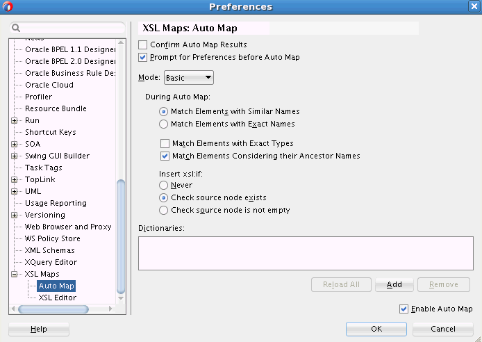
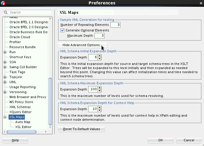
You can specify the behavior of the Auto Map feature using the Preferences dialog. Select Preferences from the Tool menu. In the navigation tree on the left, select Auto Map under XSL Maps. Figure 40-36 shows the default settings for the Auto Map preferences.
The following list describes the various Auto Map Preference settings that you can configure:
-
Confirm Auto Map Results: If you select this option, Auto Map displays a list of matching source and target elements prior to automatically mapping these elements. You can choose the matches that you'd like to be applied.
-
Prompt for Preferences before Auto Map: If you select this option, the Auto Map Preferences dialog appears every time you try to map two complex nodes.
-
Mode: Determines whether the Auto Map executes in Basic or Advanced mode. The mode selection determines the rest of the options that appear in this dialog.
The following are the rest of the options available when Basic Mode is selected:
-
Match Elements with Similar Names: Elements with similar names are matched.
-
Match Elements with Exact Names: Elements with exactly same names are matched.
-
Match Elements with Exact Types: Only elements with exactly same data types are matched.
-
Match Elements Considering Their Ancestor Names: Element path is considered along with the element name when matching.
-
Insert xsl:if: Determines if xsl:if statements are automatically inserted. The following settings are used:
-
Never: xsl:if statements are not inserted automatically.
-
Check source node exists: An xsl:if statement is inserted to check for the existence of the source node before the node is created in the output.
-
Check source node is not empty: An xsl:if statement is inserted to check that the source node is not empty before creating the node in the output.
-
The following are the rest of the options available when Advanced Mode is selected:
-
Ancestor Weight: A number between 0 and 5 indicating the emphasis to be placed on matching of ancestors. The number 0 corresponds to turning the Match Elements Considering Their Ancestor Names option off in Basic mode. The number 5 corresponds to turning the Match Elements Considering Their Ancestor Names option on in Basic mode.
-
Linguistic Weight: A number between 0 and 5 indicating the emphasis to be placed on matching of element names. The number 0 indicates that the element names need not match. The number 5 indicates that the element names must be an exact match.
-
Type Weight: A number between 0 and 5 indicating the emphasis to be placed on matching of element names. The number 0 indicates that the element types need not match. The number 5 indicates that the element types must be an exact match.
-
Match Threshold (%): The Auto Map computes a percentage match for each map (Ancestor, Linguistic, Type), and selects the highest percentage amongst these. If the highest match is above the threshold percentage, then a match is made.
-
Dictionaries: Enables you to add existing dictionaries to the Auto Map. Dictionaries can be defined from existing maps and used in subsequent maps.
40.6.2 How to Execute an Auto Map
To execute an Auto Map:
- Drag and drop a complex source node to the target element in the XSLT pane. If you are using Map View, then you'd drop the source node to a node in the target pane.
- Depending on your Auto Map Preferences, the Preferences dialog might appear. Select your Auto Map preferences, and click OK.
- Depending on your Auto Map Preferences, the Auto Map dialog might appear. Verify the matches created by the Auto Map, and click OK.
40.7 Checking the Completion Status of the Map
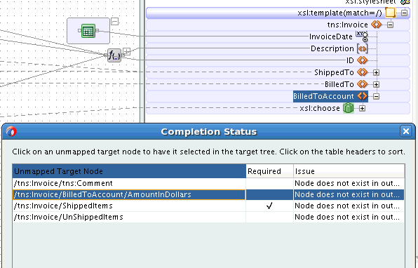
If you are using a target schema for your map, you can check the completion status of the map at any time. You can do this in both Map View and XSLT View. The completion status check flags the following:
-
All unmapped target elements and attributes. A flag indicates if the target element is a required element in the target schema.
-
Target elements mapped with incomplete XPath expressions. For instance, an XPath function, mapped to a target node, might be missing a parameter.
-
All missing target elements and attributes. A flag indicates if the missing target element is a required element in the target schema.
To check the completion status of a map, right-click the Canvas (center) pane, and select Completion Status from the context menu. The Completion Status dialog appears showing all incomplete target nodes. Clicking a row in the Completion Dialog status selects the corresponding node location in the XSLT/target tree. Figure 40-37 shows the Completion Status dialog with a missing node highlighted.
40.8 Testing the Map
The XSLT Map Editor provides a tool to test the map. To invoke the test tool, right-click the Canvas pane, and select Test from the context menu. You can use the test tool in both Map View and XSLT View.
Figure 40-38 demonstrates launching the Test XSL Map dialog.
40.8.1 How to Test the Transformation Mapping Logic
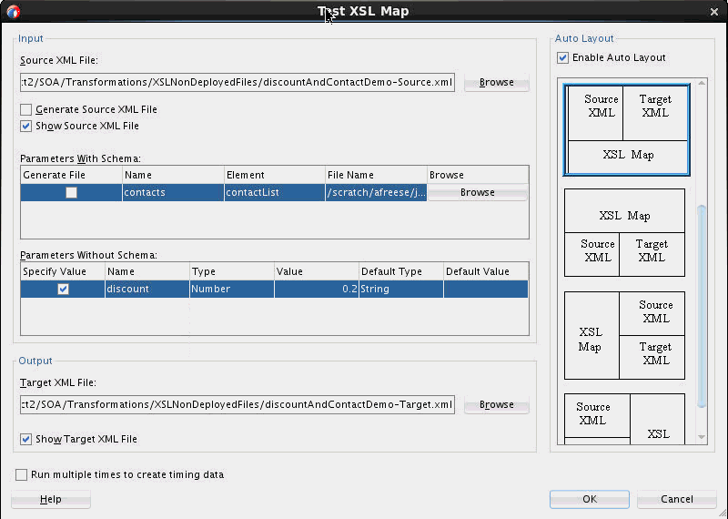
The Test XSL Map dialog shown in Figure 40-39 enables you to test the transformation mapping logic you designed with the XSLT Map Editor. The test settings you specify are stored and do not need to be entered again the next time you test. Test settings must be entered again if you close and reopen Oracle JDeveloper.
To test the transformation mapping logic:
-
In the Source XML File field, choose to allow a sample source XML file to be generated for testing or click Browse to specify a different source XML file.
When you click OK, the source XML file is validated. If validation passes, transformation occurs, and the target XML file is created.
If validation fails, no transformation occurs and a message displays on-screen.
-
Select the Generate Source XML File check box to create a sample XML file based on the map source XSD schema.
-
Select the Show Source XML File check box to display the source XML files for the test. The source XML files display in an Oracle JDeveloper XML editor.
If the map has defined parameters, the Parameters With Schema or Parameters Without Schema table can appear.
-
If the Parameters With Schema table appears, you can specify an input XML file for the parameter using the Browse button. Select the Generate File check box to generate a file.
-
If the Parameters Without Schema table appears, you can specify a value by selecting the Specify Value check box and making appropriate edits to the Type and Value columns.
-
-
In the Target XML File field, enter a file name or browse for a file name in which to store the resulting XML document from the transformation.
-
Select the Show Target XML File check box to display the target XML file for the test. The target XML file displays in an Oracle JDeveloper XML editor.
-
If you select to show both the source and target XML, you can customize the layout of your XML editors. Select Enable Auto Layout in the upper right corner and click one of the patterns.
-
Click OK.
The test results shown in Figure 40-40 appear.
For this example, the source XML and target XML display side-by-side with the XSL map underneath (the default setting). Additional source XML files corresponding to the Parameters With Schema table are displayed as tabs in the same area as the main source file. You can right-click an editor and select Validate XML to validate the source or target XML against the map source or target XSD schema.
40.8.1.1 How to Test XSLT Maps that Use DVM Lookup Functions
You can test an XSLT map that contains DVM lookup functions. If your map uses DVM lookup functions that reference local files or files in the MDS, and these files are accessible from your JDeveloper environment, then you need not perform any additional steps.
If your map uses DVM lookup functions that reference files not accessible in your JDeveloper environment, then you can create local DVM files for testing without requiring to modify the DVM references in your XSLT. Use the following steps:
40.8.1.2 How to Test XSLT Maps that Use XREF Functions
You can use the local dvm lookup file, called UnitTestXrefFunctionReturn.dvm to emulate the test. This file is automatically generated when you run the XSLT test for the first time.
The UnitTestXrefFunctionReturn.dvm file includes default responses for all the XREF functions. This simulates the expected responses when the functions execute correctly. You may modify the default responses. You can also create different return values for different calls of the same function when the parameter values are different.
The following figure shows the initial DVM file.
Figure 40-41 The UnitTestXrefFunctionReturn.dvm File

Description of "Figure 40-41 The UnitTestXrefFunctionReturn.dvm File"
The functionName column specifies the name of the function. To start with, there is only one entry for each function with the default behavior defined. All XREF functions execute with this default information. You can optionally create more entries for a given function, and enter different return values for the function based on the input parameters.
The returnValue column specifies the return value from the function. This defines what you would like to see returned from the function.
The other columns define qualifiers that you can use to differentiate one function call from another, based on the value of a given parameter. Each of these columns define a parameter available in a given function call. Not all parameters are available in all functions. When a parameter is not available, it is marked as NA (Not Available) in the original table.
40.8.1.2.1 Working with returnValue:
The returnValue column can either be defined as a text value, such as SBL_001, or may be defined by a parameter name. For instance, if we look at the first function, lookupXRef, this function has a return value of RefColumnValue. As this is the name of a parameter (RefColumnValue), the value of this parameter is the return value of the function to the XSLT.
For example, if the call to the lookupXRef function looks like the following:
lookupXRef( oramds:/apps/AIAMetaData/xref/CUSTOMERPARTY_PARTYLOCATIONID.xref",
"COMMON_ID", "COMMON_001", "SBL_ID", false())
Then the value COMMON_001 is returned, as this is the value of the RefColumnValue parameter that was passed.
For the markForDelete function, the value true is returned, converted to Boolean.
For the lookupXRef1M and lookupPopulatedColumns functions, a node-set is returned by the function. This node-set contains elements of the following form:
<column name="columnNameHere">columnValueHere</column>
As shown in Figure 40-41, the default value for the lookupXRef1M function is:
:RefColumnName:RefColumnValue:ColumnName:RefColumnValue
This encodes the column names and values for two column nodes that are returned in a node-set from the function. The first character defines the delimiter to be used in parsing the information. If your data contains a colon (:), you can use any character as the delimiter that is not in your test data, by putting that character as the first character and using it to delimit the data (say, #abc:def#abc:ghi).
For example, if we have the following function call to lookupXRef1M:
lookupXRef1M ("oramds:/mydata", "COMMON_ID", "COMMON_001", "SAP_ID", false())
Then using the default definition, for a return value of :RefColumnName:RefColumnValue:ColumnName:RefColumnValue, you would receive back two column elements:
<column name="COMMON_ID">COMMON_001</column>
<column name="SAP_ID">COMMON_001</column>
If you change the line in the DVM to have a returnValue of :SAP_ID:SAP_001:SBL_ID:SBL_001:ORCL_ID:ORCL_001, then the function returns three column nodes:
<column name="SAP_ID">SAP_001</column>
<column name="SBL_ID">SBL_001</column>
<column name="ORCL_ID">ORCL_001</column>
40.8.1.2.2 Adding Additional Rows:
You can also add additional rows to the DVM file. You can add additional rows for a function by providing different input values for the parameters resulting in different return values.
For example, if we have several lookups against the same XREF file, but want to get different values back from each lookup, we could add the following lines for lookupXRef to the DVM file:

In determining the correct return value, the design time emulator finds the first matching set of parameter values by starting at the bottom of the DVM table. The return value corresponding to the first matching row is returned.
As illustrated in the preceding figure, a call to lookupXRef("oramds:/apps/AIAMetaData/xref/CUSTOMERPARTY_PARTYLOCATIONID.xref", "COMMON_ID", "COMMON_001", "SBL_ID", false()), for example, would return the value, SBL_001.
A call to lookupXRef("oramds:/apps/AIAMetaData/xref/CUSTOMERPARTY_PARTYLOCATIONID.xref", "COMMON_ID", "COMMON_002", "SBL_ID", false()), on the other hand, does not match any of the last three rows, and returns the default value COMMON_002 (the value of the parameter, RefColumnValue).
40.8.2 How to Generate Reports
You can generate an HTML report with the following information:
-
XSL map file name, source and target schema file names, their root element names, and their root element namespaces
-
Target document mappings
-
Target fields not mapped (including mandatory fields)
-
Sample transformation map execution
Follow these instructions to generate a report.
40.8.3 How to Customize Sample XML Generation
You can customize sample XML generation by specifying the following parameters. Select Preferences > XSL Maps in the Tools main menu of Oracle JDeveloper to display the Preferences dialog. You can modify the following settings under Sample XML Generation:
-
Number of repeating elements
Specifies how many occurrences of an element are created if the element has the attribute
maxOccursset to a value greater than1. If the specified value is greater than the value of themaxOccursattribute for a particular element, the number of occurrences created for that particular element is themaxOccursvalue, not the specified number. -
Generate optional elements
If selected, any optional element (its attribute
minOccursset to a value of0) is generated the same way as any required element (its attributeminOccursset to a value greater than0). -
Maximum depth
To avoid the occurrence of recursion in sample XML generation caused by optional elements, specify a maximum depth in the XML document hierarchy tree beyond which no optional elements are generated.
40.9 Importing an External XSLT Map
If you have an XSLT map that has been developed with an editor other than JDeveloper, you can import it into JDeveloper.
To import an external map:
40.10 Using Variables and Parameters
You can add variables and parameters to the XSLT map. These are available in both Map View and XSLT View.
40.10.1 How to Add Global Variables
Global variables can be used in both Map View and XSLT View.
To create a global variable:
40.10.3 How to Add Local Variables in XSLT View
In XSLT View, local variables are added in the same manner as other XSLT elements. See How to Add XSLT Statements for details about adding XSLT elements using the context menu or Components window.
So, for example, if you select Insert Sibling Before > XSL > Variable from the context menu of an XSLT node, you get the Variable dialog box. Enter the name of the variable, optionally specify a namespace, and click OK.
The variable appears at the appropriate place in the XSLT/target pane. You can choose to map XPath expressions to the variable to set the value of the variable.
The variable also appears in the source tree under the Variables folder. This enables you to map from the variable to other XPath expressions or XSLT nodes.
To determine if the variable is in scope for a particular XSLT node or XPath expression, select the XSLT node or XPath expression. If the variable is in scope for the XSLT node or XPath expression, then the variable appears in bold in the source tree. If the variable is not in scope for the selected XSLT node or XPath expression, then the variable appears disabled in the source tree.
Only scalar variables can be defined. You cannot define the structure of a variable. If the variable you are referencing represents a complex structure, you can reference nodes within the structure by entering the appropriate XPath expression manually.
Note:
If you are using XSLT 1.0, and using a complex variable, it might be necessary to wrap the variable in the ora:node-set function before an XPath expression can be used to access nodes within the variable.
For example, say the myVar variable has the following structure:
<xsl:variable name="myVar">
  <A>
     <B>sometext</B>
  </A>
</xsl:variable>
The text in B can be referenced as ora:node-set($myVar)/A/B. The node-set function is not necessary in XSLT 2.0.
40.10.4 How to Add Global Parameters
Parameters can be added to the XSLT map editor both as global parameters and named template parameters.
You can add global parameters when creating an XSLT map. See How to Create an XSLT Map for more details. You can also add global parameters to an existing map.
To add a global parameter to an existing map:
The parameter node appears at the appropriate place in the target pane (for Map View) or XSLT pane (for the XSLT View). This enables you to map XPath expressions to the parameter to set the parameter's default value.
The parameter also appears in the source tree. This enables you to map the parameter to XPath expressions or nodes in the XSLT tree.
Note:
You can also add parameters like other XSLT elements. See How to Add XSLT Statements for details about adding XSLT elements using the context menu or Components window.
40.11 Substituting Elements and Types
You can substitute elements and types in the source and target trees.
Use element substitution when:
-
An element is defined as the head of a substitution group in the underlying schema. The element may or may not be abstract. Any element from the substitution group can be substituted for the original element.
-
An element is defined as an
anyelement. Any global element defined in the schema can be substituted.
Use type substitution when:
-
A global type is available in the underlying schema that is derived from the type of an element in the source or target tree. The global type can then be substituted for the original type of the element. Any type derived from an abstract type can be substituted for that abstract type.
-
An element in the source or target tree is defined to be of the type
anyType. Any global type defined in the schema can then be substituted.
Type substitution is supported by use of the xsi:type attribute in XML.
To substitute an element or type in the source and target trees:
40.12 Using Named Templates
You can add named templates to the XSLT map. These templates can be edited within the XSLT Map Editor. You can invoke named templates by using the xsl:call-template instruction.
Named templates can only be used with the XSLT View. Once you add a named template in an XSLT map, the map can only be opened in XSLT View.
40.12.2 How to Edit a Named Template
When a named template is first created, it is opened for editing in the XSLT Map Editor. You can switch between editing the named template and editing the XSLT map by using the drop-down list in the XSLT toolbar.
Figure 40-47 shows a named template being edited in the XSLT Map Editor. The top-left hand corner has a drop-down list that lets you choose between the XSLT map and the named template (createStreet).
The source tree, any global parameters, and the named template parameters appear in the source pane on the left. The XSLT pane on the upper right represents the XSLT associated with the named template. If a target schema is used, then the target tree appears at the bottom-right corner of the editor.
40.12.3 How to Add Parameters to an Existing Named Template
To add parameters to an existing named template:
40.13 Using Template Rules
Template rules are xsl:template statements with match attributes. Template rules are supported by the XSLT Map Editor. You can use template rules in the XSLT View only. Template rules are not supported in the Map View.
The XSLT Map Editor enables you to add template rules in various ways. You can insert the template rule manually, or refactor an existing mapping to create a template rule.
When adding the template rule manually, you also need to insert an apply-templates statement to invoke the template at the appropriate place in the XSLT. When refactoring an existing map to create a template rule, the apply-templates statement is inserted automatically.
40.13.1 How to Create a Template Rule
40.13.1.1 Example: Creating a Template Rule
As an example, let us create a template rule for an existing map, as shown below:
This example seeks to create a single template that processes the Address information in the source ShipTo and BillTo elements to create the Address in the ShippedTo and BilledTo elements in the target. The following steps illustrate the process:
-
Right-click the Address node under the ShipTo or BillTo node in the source pane, and select New Template Rule from the context menu that appears.
The New Template Rule dialog appears. The Match Node is pre-populated with the path to the Address node that you selected in the source pane. This match string is specific to the Address element under ShipTo, but we need to create a template that will process any Address field in the source document.
-
Modify the Match Node string to contain only the name Address. This will match all Address nodes in the source document irrespective of where they appear in the document.
-
Select the Select nodes to generate in template option. The target schema tree appears.
When the template rule is invoked, we would like to create the Address element in the target, along with its children.
-
Select the Address node under the ShippedTo or the BilledTo element, as both elements have identical structures.
-
To select the children of the Address node, press and hold down the Shift key, and click the Zip element, which is the last child of the Address element. This selects the Address element and all its children.
-
Click OK to create the template rule.
As the rule is not yet invoked anywhere in the map, a warning icon appears against the template, and the nodes that the template creates have question mark (?) icons against them.
40.13.1.1.1 Invoking the Template
Next, we need to invoke the template for both the ShipTo and BillTo Address elements in the source to create the ShippedTo and BilledTo Address elements in the target. We need to create apply-templates statements in the XSLT at the places where we would like to create these Address elements. The following steps describe the process.
-
Right-click the Invoice node in the XSLT pane, and select Add Children From Schema > BilledTo from the context menu that appears. The BilledTo node is inserted along with its required child nodes.
-
Right-click the Invoice node in the XSLT pane, and select Add Children From Schema > ShippedTo from the context menu that appears. The ShippedTo node is inserted along with its required child nodes.
-
Right-click the ShippedTo/Address node and select Delete. Repeat the same for the BilledTo/Address node. We would create the Address nodes using the template rule that we created.
-
Right-click the ShippedTo node and select Append Child > XSL > apply-templates from the context menu that appears. The xsl:apply-templates statement is added.
-
Right-click the BilledTo node and select Append Child > XSL > apply-templates from the context menu that appears. The xsl:apply-templates statement is added.
-
Drag a line from the ShipTo/Address node in the source pane to the ShippedTo/apply-templates node in the XSLT pane. This sets the select attribute of the
apply-templatesstatement, so that only the ShipTo/Address node is processed by thexsl:apply-templatesstatement. -
Drag a line from the BillTo/Address node in the source pane to the BilledTo/apply-templates node in the XSLT pane. This sets the select attribute of the
apply-templatesstatement, so that only the BillTo/Address node is processed by thexsl:apply-templatesstatement.At this point, the warning icon on the template rule disappears, as we have defined the template invocation. If you click the template rule, the two source Address nodes processed by the template are highlighted, as illustrated in the following figure.
Next, the nodes below the template rule can be mapped.
-
Drag and drop lines from the elements under the BillTo/Address node, or the ShipTo/Address node, to the appropriate elements under the Address template rule.
As you drag from either source Address (BillTo or ShipTo), lines are drawn to both source addresses. This is because both BillTo/Address and ShipTo/Address are context nodes for the template.
The source code for the template now appears as follows:
  <xsl:template match="Address">
    <Address country="{@country}">
      <Street>
        <xsl:value-of select="concat (Street1, ', ' , Street2 )"/>
      </Street>
      <City>
        <xsl:value-of select="City"/>
      </City>
      <State>
        <xsl:value-of select="State"/>
      </State>
      <Zip>
        <xsl:value-of select="Zipcode"/>
      </Zip>
    </Address>
  </xsl:template>
40.13.2 How to Refactor an Existing Map to Create a Template Rule
You can refactor code from an existing template to create a new template rule. This is useful if the template rule that is created can be reused in multiple places, as was the case with the Address template rule created in the previous section.
The Create in Template option enables you to refactor a section of XSLT instructions into a separate template that can be invoked from multiple places.
In the following example, we refactor an existing mapping to create a template rule.
In the following map, the XSLT that processes each Address element in the source is repeated for each Address node. For easier maintenance, you may want to consolidate redundant code into reusable templates. This way, if the code is later updated, you would not have to update multiple copies.
In the preceding map, if the XPath concat expression that creates Street from Street1 and Street2 needs to be modified, there are two copies that would have to be modified. However, if the concat function exists in a single template that is reused to produce both Address elements, then only one concat statement needs to be modified in future.
In the following steps, we refactor the existing mapping to create a single template that processes the Address elements:
40.14 Using the Execution View
The Execution View displays the order of execution of your XSLT statements. When creating complex XSLT that uses named templates and template rules, it can get difficult to determine the order of execution of XSLT templates. The Execution View helps you troubleshoot issues by creating an execution tree for your XSLT.
The execution tree shows when the output nodes are created, and shows exactly which templates are invoked at various points during the XSLT execution.
40.14.1 How to Use Execution View to Prevent or Troubleshoot Runtime Errors
To launch the Execution View dialog, right-click the canvas (center) pane, and select Execution View. Alternatively, click the Execution View for XSLT Map button on the XSLT toolbar.
The Execution View is available in both the Map and XSLT views. However, it is most useful when the map contains multiple templates and the user needs to figure out as to where the templates are being invoked.
Figure 40-49 shows the Execution View dialog for an XSLT map that contains multiple templates. As per the execution view, the root template with match='/' executes first. This is followed by the creation of the Invoice, Description, and ID nodes. An apply-templates statement then invokes the ShipTo template followed by an apply-templates statement that invokes the BillTo template. Other nodes and templates are then created.
Figure 40-49 Execution View Dialog and Corresponding XSLT Tree
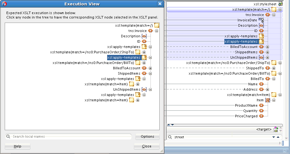
Description of "Figure 40-49 Execution View Dialog and Corresponding XSLT Tree"
If you click an element in the Execution View tree, the corresponding element is highlighted in the XSLT tree. For example, as shown in Figure 40-49, if you want to locate the apply-templates node that invokes the BillTo template, select the apply-templates node in the Execution View and the corresponding apply-templates statement is highlighted in the XSLT pane.
Execution View also shows calls to named templates. When you select a node inside a named template call in the Execution View tree, the XSLT editor view is refreshed to show the selected node in the named template implementation.
Execution View helps you understand the overall flow of an XSLT stylesheet. Using the Execution View, you can locate issues related to templates that are not invoked, or apply-templates statements that are invoking incorrect templates.
When using imported named templates or template rules, Execution View shows the corresponding calls, and you can use Execution View to troubleshoot problems like import precedence. However, Execution View cannot navigate to the external XSLT files.
40.14.1.1 Searching for Nodes
The Execution View dialog has a search facility that enables you to search for specific nodes in the Execution View tree. Click in the Search local names field, and type a name to search.
40.14.1.2 Setting Display Options
You can choose to show or hide certain XSLT elements in the execution tree. Click Options to bring up the Execution View Options dialog. Figure 40-50 shows the default selections in Execution View Options.
Figure 40-50 Default Execution View Options
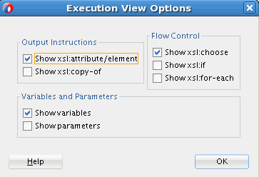
Description of "Figure 40-50 Default Execution View Options"
40.15 Debugging the XSLT Map
Starting in 12.2.1, you can debug your XSLT maps using the SOA Debugger. You can add breakpoints at strategic locations in the XSLT map. When debugging, the debugger halts execution at the breakpoints, enabling you to verify the data and output.
XSLT maps can be complex, making them difficult to debug. For example, you may have a Java function, or other functionality, that is best tested in the application server. Also, you might find it easier to debug in the application environment, as the XSLT may be invoked from many different applications in the server. The SOA debugger provides remote debugging capability for XSLT maps that have been deployed in the application server.
You can debug any XSLT transformation used in a BPEL process or Mediator. When the BPEL process or Mediator is invoked in the composite, the debugger pauses at the breakpoints defined in the map. The XSLT map opens in JDeveloper and user data corresponding to the XSLT processing appears in the Data window.
You can also use the debugger with your Oracle Service Bus projects. For more details on using the debugger with Service Bus projects, refer to:
40.15.1 Setting Breakpoints in the XSLT Map Editor
You can set breakpoints in the Design view of the XSLT Map Editor. This enables you to debug your XSLT map at runtime, using test data or payload.
Before you can set breakpoints, make sure that the XSLT map is open and the Design tab is selected.
Use one of the following methods to set a breakpoint:
-
Click the breakpoint bar to the right of an XSLT element or node.
-
Right-click the breakpoint bar to the right of an XSLT element, or node, and select Toggle Breakpoint from the context menu that appears.
-
Right-click an XSLT element, and select Debug > Toggle Breakpoint from the context menu that appears.
Note:
You can also use the preceding steps to remove existing breakpoints.You can also choose to disable a breakpoint by selecting Disable Breakpoint from the context menus mentioned above. Disabled breakpoints show as gray icons in the breakpoint bar.
The following image shows a breakpoint set against the ponumber node.
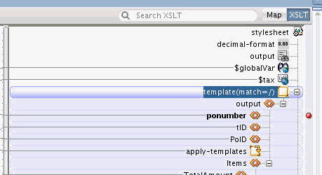
40.15.2 Running the Debugger on the XSLT Map
Initiating a Debugging Session
After setting the breakpoints for your XSLT map, follow these instructions to start the SOA debugger:
Debugging a SOA Composite Application
Note:
For the debugger to step into the XSLT map, the map must be invoked by a mediator or BPEL process in your SOA composite.Working with the Debugger in the XSLT Map Editor
After you run the debugger, and when the debugger comes across a breakpoint in the XSLT map, the debugger stops execution at the breakpoint. A blue arrow to the left of the breakpoint bar indicates the current position of the debugger. Also, a flashing blue icon appears against the corresponding XSLT element or node.
When the debugger is stepping through the XSLT map, all valid breakpoints in the XSLT editor change to red and green dots. Breakpoints that remain a solid red are currently invalid and are ignored by the debugger.
Note:
Some processes that invoke the XSLT map have time-out limits. If the debugger ends unexpectedly after exiting an XSLT map, the invoking process may have a time-out value defined. This time-out value may need to be redefined to support debugging the full process. Check server log files for information in the event of the debugger unexpectedly aborting.The following example image shows breakpoints, as they appear during runtime. The breakpoints appear against the tID and Item elements. The debugger is currently at the Item node, as indicated by the blue arrow and flashing icon.
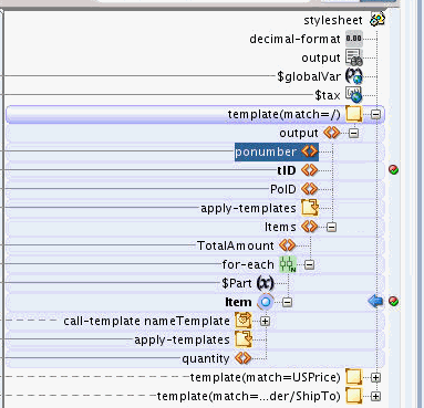
You can use the Step Over button in the main JDeveloper toolbar to step through the execution. The Step In button can be used to step into loops, call-template, apply-template, and apply-imports.The Step Out button can be used to step out of call-template, apply-template and apply-imports to the next XSLT statement.

At any point during the execution, you can look at the current values of parameters and variables in the Debugger Data window. The Data window also shows you the Context Node, Context Position, Context Size, and the Output Document being built by the XSLT processing. You can also choose to add any item visible in the Debugger Data window to the Watches window.
The following image shows sample debugger data, as it appears in the Data window on the right.
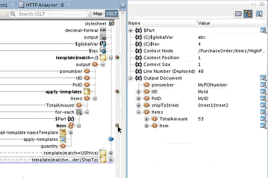
You can choose to edit the XSLT when debugging. You would need to redeploy the project before you can debug again.
40.15.3 Viewing Breakpoints
Breakpoints appear on the breakpoint bar along the right edge of the XSLT Map Editor. You can choose to see a list of all breakpoints in the XSLT map or the SOA project.
Viewing a List of All Breakpoints in the XSLT Map
Use one of the following methods to see all breakpoints in the current XSLT map:
-
Right-click anywhere in the center canvas pane and select Breakpoints from the context menu that appears.
-
Right-click anywhere on the breakpoint bar and select Breakpoints from the context menu that appears.
-
Click Breakpoints in the XSLT toolbar.
The Breakpoints dialog appears, listing all breakpoints in the XSLT map. If a breakpoint is currently hidden in the XSLT pane, you can navigate to it by clicking the breakpoint in the Breakpoints dialog.

You can also use the Breakpoints dialog to disable or delete one or more breakpoints. A disabled breakpoint would appear as a grey dot on the breakpoint bar.
The Valid column indicates if a breakpoint is currently valid. Breakpoints can become invalid if edits to the XSLT map makes them invalid. You can choose to delete invalid breakpoints. Alternatively, invalid breakpoints can become valid again if you undo the changes made to the XSLT map.
Viewing all Breakpoints in the Current Project
The JDeveloper Breakpoints window shows all breakpoints in the current project. Select Breakpoints from the Window menu to see the Breakpoints window. You can double-click a breakpoint in the Breakpoints Window to navigate to that breakpoint in the project. You can also edit or delete breakpoints from the Breakpoints window. However, you cannot add a breakpoint from the Breakpoints window.
40.15.4 Setting Conditions for XSLT Breakpoints
You can set conditions for breakpoints, so that the execution is halted only when the breakpoint condition evaluates to true.
40.16 Troubleshooting Memory Issues
If you work with large schema documents, you may sometimes encounter an out-of-memory error during auto-mapping, or during test and report generation. If you receive an out-of-memory error when using the XSLT Map Editor, you must increase the heap size of the JVM to resolve the problem.
To increase the JVM heap size:
40.17 Setting XSL Map Preferences
Use the Preferences dialog to set preferences related to XSLT maps, such as expansion depth, and the XSLT Map Editor, such as initialization options.
40.17.1 How to Set XSLT Map Preferences
To set XSLT map preferences, select Preferences from the Tools menu. Click XSL Maps in the navigation tree that appears in the left pane of the Preferences dialog. Figure 40-51 shows the XSL Maps dialog that appears.
You can set various options such as the expansion depth of the source and target trees. You can click the Help button for more information on each field.
40.17.2 How to Set the XSL Editor Preferences
To set XSLT map preferences, select Preferences from the Tools menu. In the navigation tree that appears in the left pane of the Preferences dialog, click the plus sign (+) next to XSL Maps. This expands the XSL Maps node. Select XSL Editor. Figure 40-52 shows the XSL Editor Preferences dialog.
You can set various preferences for the XSLT Map Editors, such as the initialization mode. Click Help for more information on each field.
40.17.3 How to Import a Customization File to Specify Display Preferences in the XSLT Map Editor
You can specify a customization file containing display preferences for the XSLT Map Editor. In the XSL Editor Preferences dialog (Figure 40-52), click the Browse button to the right of the Custom Display Options Config File field. Select the file to import.
The customization file is an XML file that must conform to the XSLTEditorOptions.xsd schema located in the bpm-ide-common.jar file at:
oracle/tip/tools/ide/common/resource/XSLTEditorOptions.xsd
The following example shows a sample customization file. The important elements in the file are described following the example.
<?xml version="1.0" encoding="UTF-8" ?>
  <customizeXSLTeditor>
      <selectedArea>HL7</selectedArea>
      <abbreviationLists>
          <abbreviationList name="Siebel">
              <abbreviation long="Account" short="Acct"/>
          </abbreviationList>
          <abbreviationList name="SalesGeneral">
              <abbreviation long="SalesOrder" short="SO"/>
              <abbreviation long="PurchaseOrder" short="PO"/>
              <abbreviation long="BillOfMaterial" short="BOM"/>
              <abbreviation long="CreateEngineeringChangeOrderList" short="CECOL"/>
          </abbreviationList>
      </abbreviationLists>
      <customization area="HL7">
          <showFixedValueInElementName>
               <path>@LongName</path>
               <path>@LongName2</path>
               <path>@Name</path>
          </showFixedValueInElementName>
          <abbreviations>
             <apply display="treeLabels">
                 <hideText part="matchValue" maxLength="13" hide="left"/>
                 <hideText part="namedTemplateName" maxLength="15" hide="left"/>
                 <hideText part="importHref" maxLength="20" hide="left"/>
             </apply>
             <apply display="dropDownLists">
                 <hideText part="namedTemplateName" maxLength="40" hide="center"/>
             </apply>
          </abbreviations>
      </customization>
      <customization area="AIA">
          <abbreviations>
             <applyAbbreviations list="Siebel"/>
             <applyAbbreviations list="SalesGeneral"/>
             <apply display="treeLabels">
                 <hideText part="matchValue" maxLength="13" hide="left"/>
                 <hideText part="namedTemplateName" maxLength="15" hide="left"/>
                 <hideText part="importHref" maxLength="20" hide="left"/>
             </apply>
             <apply display="dropDownLists">
                 <hideText part="namedTemplateName" maxLength="40" hide="center"/>
             </apply>
          </abbreviations>
      </customization>
  </customizeXSLTeditor>
The following list describes the important elements in the preceding example:
-
<selectedArea>:Selects the customization area to be used by the editor. A list of customization areas may be defined in the file. -
<abbreviationList name="listName">:Defines an abbreviation list that can be referenced by a customization area. -
<abbreviation name="Account" short="Acct">:Defines a specific abbreviation to use in an abbreviation list. -
<abbreviations>:Used within a customization area to define abbreviations and cut-off lengths for text in the editor. -
<applyAbbreviations>:Selects an abbreviation list or lists to use in this customization area. -
<apply display="treeLabels" | "dropDownLists">:Selects an area where text cut-offs occur. -
<hideText>:Selects specific text fields to cut-off when they are too long. -
@part:Either"matchValue", "namedTemplateName",or"importHref". -
@maxLength:Text value length limit. -
@hide:Specifies portion of the text to hide,"left"truncates the text on the left side,"right"truncates the text on the right side,"center"removes text in the center replacing it with '…'. -
<showFixedValueInElementName>:Used within a customization area. This element selects fixed value attributes that contain the long name or other text that the user wants to see displayed as part of the element name in the editor source or target tree.For example:
<showFixedValueInElementName>
   <path>@LongName</path>
   <path>@LongName2</path>
   <path>@Name</path>
</showFixedValueInElementName>
In the preceding example, the first fixed attribute found on any element in the XSLT Map Editor trees with the name
LongName, LongName2,orNameis shown as part of the element tree name.The fixed attribute value is shown in parentheses to the right of the actual element name in the tree. This is particularly useful for HL7 schemas where descriptive names are added as fixed attribute values in the schema.
