43 Creating a Sample Socket Transport Provider
This chapter describes how to build and run the sample socket transport provider. This sample and its source code are installed with Service Bus. The sample serves as an example implementation of a custom transport provider.
This chapter includes the following sections:
43.1 Sample Socket Transport Provider Design
The primary purpose of the sample socket transport provider is to serve as an example transport provider implementation.
This publicly available sample demonstrates the implementation and configuration details of the Transport SDK.
43.1.1 Concepts Illustrated by the Sample
The sample transport is designed to send and receive streamed data to and from a configured TCP socket in Service Bus. The sample transport illustrates the following Transport SDK concepts:
-
Implementing the set of Transport SDK APIs that are required to build a custom transport.
-
Performing transport endpoint validations, such as checking that no socket endpoint is listening on the configured address.
-
Implementing several UI configuration options, including socket properties and message patterns.
-
Implementing a one-way or synchronous request-response message pattern.
-
Using POJOs (Plain Old Java Objects) for metadata and headers of endpoint requests and responses.
-
Using streaming in Service Bus pipelines.
43.1.2 Basic Architecture of the Sample
Figure 43-1 shows the basic architecture of the sample socket transport provider. Any client can connect to the server socket. Data is received at the server socket and passes through the pipeline. The response comes back through the outbound transport. The response is finally sent back to the inbound transport and back to the client.
Figure 43-1 Sample Socket Transport Architecture
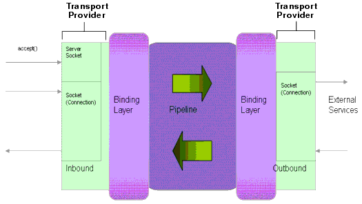
Description of "Figure 43-1 Sample Socket Transport Architecture "
43.1.3 Configuration Properties
Figure 43-2 illustrates the configuration properties for the transport endpoint. These properties are configured in the schema file, SocketTransport.xsd. For the location of this file, see Sample Location and Directory Structure .. This file allows you to extend the basic set of properties defined in the common schema provided with the SDK. Refer to the SocketTransport.xsd file for information on each of the properties.
Tip:
For more information about these configuration properties, see Step 4. Define Transport-Specific Artifacts .
Figure 43-2 SocketEndpointConfiguration Properties
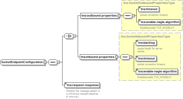
Description of "Figure 43-2 SocketEndpointConfiguration Properties"
Also in the SocketTransport.xsd file are the request and response header and metadata properties, as illustrated in Figure 43-3. Refer to the SocketTransport.xsd file for more information about these properties.
Figure 43-3 Request and Response Header and Metadata Configurations
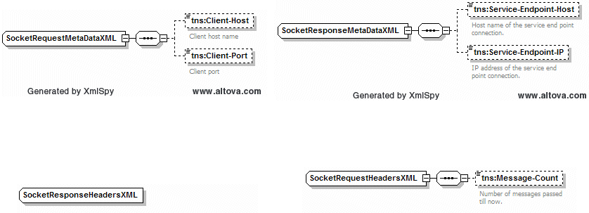
Description of "Figure 43-3 Request and Response Header and Metadata Configurations "
43.2 Sample Location and Directory Structure
This section briefly describes some of the key folders in the sample project. You can use this directory structure as a model for developing your custom transport provider.
After you create a sample domain, the sample transport should be in the Oracle_Home\user_projects\applications\[Sample_Domain]folder.
Table 43-1 lists and briefly describes key sample-transport directories.
Table 43-1 Key Sample Transport Provider Directories
| Directory | Description |
|---|---|
|
build |
This directory is created when you build the sample socket transport. It contains the built and packaged transport for use in Service Bus. |
|
l10n |
This directory contains these internationalization files. There is one of each file for each supported locale.
|
|
META-INF |
This directory contains these application deployment descriptor files:
|
|
offline |
This directory contains one file, |
|
resources |
This directory contains the socket transport provider configuration file used by the Transport SDK, which is named |
|
schemas |
This directory contains the relevant schemas defined for this transport, in this case, |
|
src |
This directory contains the source tree of the sample transport. |
|
test |
This directory includes a testing utility for the sample transport provider, along with the source tree for the test server and client. |
|
webapp |
This directory contains the deployment descriptors required for the sample transport help web application. |
The following Ant build files are also located in the sample-transport directory:
-
build.properties– Properties file for Ant. -
build.xml– An Ant build file with different targets for compile, build, stage, and deploy.
43.3 Building and Deploying the Sample
Perform the steps provided in this section in the order given to build and deploy the sample transport provider.
43.3.1 How to Set Up the Environment
A script is provided in the Service Bus domain to configure the environment for building the sample.
To set up the environment:
43.3.2 How to Build the Sample Transport Provider
Once you set the environment configuration, you can build the transport using the Ant build files provided in the sample-transport directory.
To build the sample transport provider:
43.3.3 How to Deploy the Sample Transport Provider
The sockets sample also provides automated scripts for you to deploy the sample transport provider to the WebLogic Server. Once the sample is built and staged successfully, you can run the deploy command.
To deploy the sample transport provider:
43.4 Creating a Socket Transport Sample Project
The sample consists of a test server and a test client. The client sends a message to the server. You configure Service Bus to receive and process the message.
Perform the tasks in this section in the order given. These instructions are for creating the sample project in the Oracle Service Bus Console, but you can do this in JDeveloper as well.
43.4.1 Creating the Project
The first step to creating the sample is to create the actual project that will contain the Service Bus resources.
To create the project:
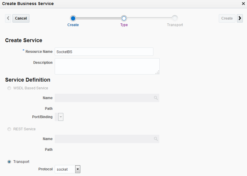
43.4.2 Creating the Business Service
In the sample project, you create a business service to talk to the server.
To create the business service:
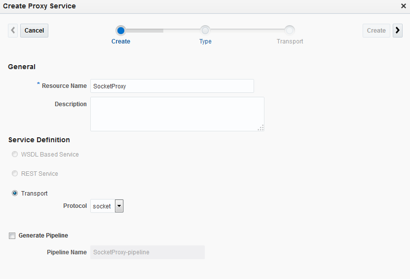
43.4.3 Creating the Proxy Service
In this section, you create a proxy service to accept messages from the client.
To create the proxy service:
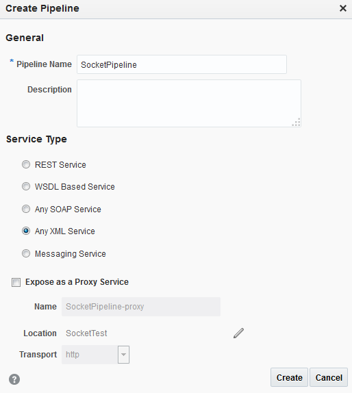
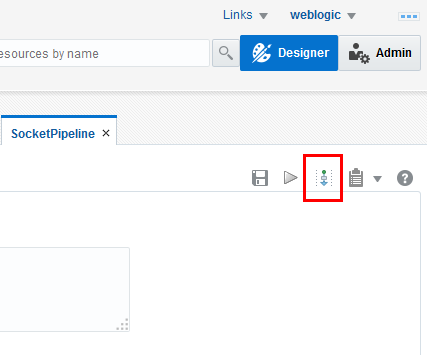
43.4.4 Creating the Pipeline
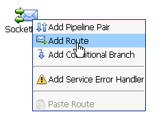
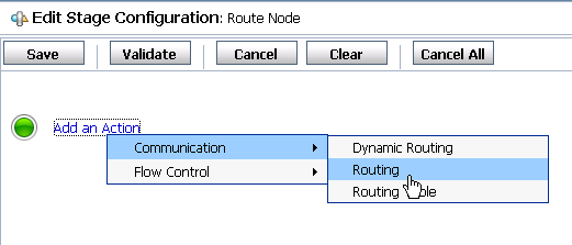
Now that the business and proxy services are defined, you can create a pipeline to route incoming messages to the business service.
To create the pipeline:
43.5 Testing the Socket Transport Provider
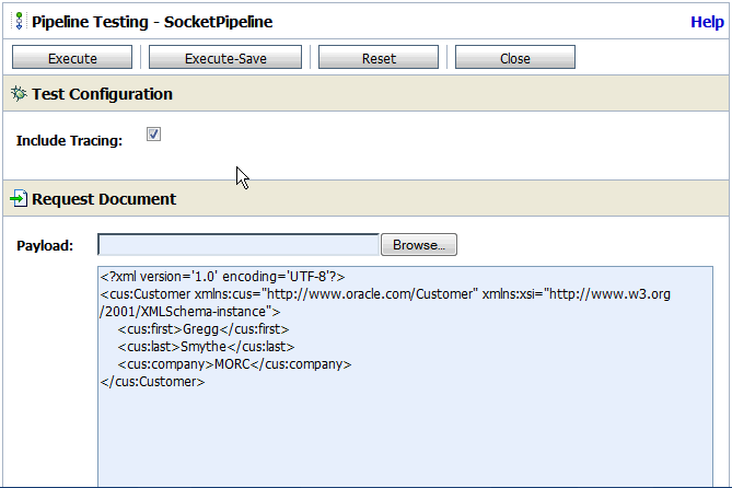
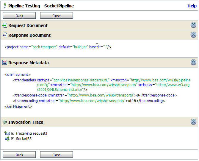
You can test the socket transport provider using the client and server tools provided with the sample files, and you can test project components using the Test Console in the Oracle Service Bus Console.
43.5.1 Using the Sample Server and Client for Testing
The sample project includes a simple socket server and a client to test the socket transport provider. First you need to start the sample server and client, and then you can work with the Test Console to test the transport provider.
43.5.1.1 Starting the Sample External Service
Run the following command from the sample-transport directory to start the test server, which is a server socket that listens on a specified port and receives and sends the messages.
java -classpath .\test\build\test-client.jar -Dfile-encoding=utf-8
-Drequest-encoding=utf-8 com.bea.alsb.transports.sample.test.TestServer 7031
<message-file-location>
7031 is the port number in the business service endpoint URI, where ServerSocket is listening. The file and request encoding indicate the encoding of the request and response. message-file-location is the path and name of the message file to send as a response to the business service.
If the server is started successfully, a message appears indicating that it is started and listening on a socket. If you specify a file to process, the text of the file appears in the command window.
43.5.1.2 Starting the Sample Initiating Service
Run the following command to start the initiating socket service, which is a client to the configured socket proxy service. It sends a message and receives the response from Service Bus.
java -classpath .\test\build\test-client.jar -Dfile-encoding=utf-8
-Dresponse-encoding=utf-8 com.bea.alsb.transports.sample.test.TestClient
<host-name> <port> <thread-ct> <message-file-location>
where:
-
host-nameis the host name on which the Service Bus server is located. -
portis the port number at which the proxy service is listening (7032, in our example). -
thread-ctis the number of clients that can send a message to Service Bus. -
message-file-location(optional) is the location of the message file to send as a response to the business service. -
file-encodingis an optional argument specifying the encoding of the file. The default isutf-8. -
response-encodingis the encoding of the response received from the socket proxy service. The default isutf-8.
