| Oracle® Application Server Adapter for PeopleSoft User's Guide 10g Release 3 (10.1.3.1.0) Part Number B28997-01 |
|
|
View PDF |
| Oracle® Application Server Adapter for PeopleSoft User's Guide 10g Release 3 (10.1.3.1.0) Part Number B28997-01 |
|
|
View PDF |
This chapter contains the following examples:
The scenarios shown in this chapter require the following prerequisites.
Prerequisites
The following are installation and configuration requirements:
OracleAS Adapter for PeopleSoft must be installed on Oracle Application Server.
PeopleSoft must be configured for inbound and outbound processing..
OracleAS Technology adapters must be deployed and properly configured.
See Also:
Oracle Application Server Adapter Installation GuideThe examples in this chapter present the configuration steps necessary for demonstrating service and event integration with PeopleSoft. Prior to using this material, you must be familiar with the following:
How to configure OracleAS Adapter for PeopleSoft for services and events. For more information, see Chapter 2, "Configuring OracleAS Adapter for PeopleSoft".
How to configure a new Application Server and Integration Server connection in Oracle JDeveloper. For more information, see Chapter 4, "Integration with Oracle BPEL Process Manager".
Overview of InterConnect Integration
ESB provides a comprehensive application integration framework. OracleAS Adapter for PeopleSoft used in conjunction with ESB enables you to seamlessly integrate enterprise software, eliminating the need to write custom code. Functional modeling, as opposed to custom coding solutions, allows for software reuse and reduces the complexity and management challenges that arise over the software lifecycle. This integration model consists of two components--high-level integration logic and low-level platform services.
Adapter integration with OracleAS ESB is a two-step process:
Design Time: OracleAS Adapter for PeopleSoft is configured in Application Explorer for services and events, as described in Chapter 2, "Configuring OracleAS Adapter for PeopleSoft". Integration logic is modeled in iStudio. Metadata are stored in repositories.
Runtime: The underlying platform treats this metadata as runtime instructions to enable the communication between participating applications.
Namespace Requirements
The purpose of an XML namespace is to allow the deployment of XML vocabularies (where element and attribute names are defined) in a global environment and to reduce the risk of name collisions in a given document when vocabularies are combined. Qualified namespaces are used for stricter schema validation. In documents conforming to this specification, element and attribute names appear as qualified names. Syntactically, they are either prefixed names or unprefixed names. An attribute-based declaration syntax is provided to bind prefixes to namespace names and to bind a default namespace that applies to unprefixed element names. These declarations are scoped by the elements on which they appear so that different bindings may apply in different parts of a document. Processors conforming to this specification must recognize and act on these declarations and prefixes.
In the 10.1.3.1.0 SOA release, the recommendations for ESB integrations is to perform stricter name space validations. As a result, Application Explorer generates Web services for the backend with the namespace marked as ÒQualifiedÓ. This means that during testing or usage phases of this service by ESB, the request XML document that is used should adhere to the schema and WSDL document. Once again, it is important to remember that the namespaces are qualified. To further understand this point, the difference is illustrated with the following example:
Input XML for ESB based on unqualified namespaces:
<?xml version="1.0" encoding="UTF-8"?><PS8> <component perform="browse">LOCATION</component> <key name="Setid">SHARE</key> <key name="Location">ALBERTA</key> </PS8>
Input XML for ESB based on qualified namespaces:
<PS8 xmlns="urn:iwaysoftware:adapter:peoplesoft:ci"> <component perform="find">LOCATION</component> <key name="Setid">SHARE</key> <key name="Location">ALBERTA</key></PS8>
Note: If you are passing an unqualified input against a WSDL document that is expecting qualified namespaces, ESB will throw the exception as ÒUnable to process input xml...."
The following example describes how to configure an ESB outbound process to your PeopleSoft system, using an ESB project in Oracle JDeveloper.
Prerequisites
Before you proceed, you must create an outbound WSDL file for the adapter by using the following steps:
Create a target using Application Explorer.
Connect to the target.
Create a WSDL file.
Restart the Oracle Application Server.
Creating an Outbound ESB Project and Assigning an Outbound WSDL File
At the top of the upper left pane, click the Applications Navigator tab.
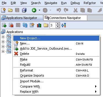
Right-click an application node that you created and select New Project.
The New Gallery window is displayed.
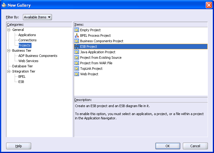
From the Items list, select ESB Project and click OK.
The Create ESB Project dialog box is displayed.
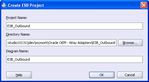
Perform the following steps:
Specify a name for the ESB project.
The Directory Name field and Diagram Name fields are updated automatically.
Click OK.
The ESB project is added at the top of the upper left pane.
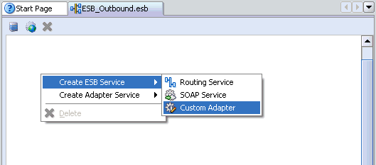
Right-click the ESB project in the middle pane, select Create ESB Service followed by Custom Adapter.
The Create Adapter Service dialog box is displayed.
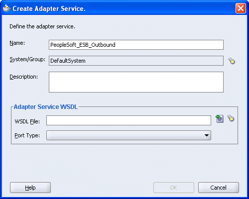
Enter a name for the adapter service and click the Service Explorer icon (second icon from the left preceding the WSDL File field).
The Service Explorer dialog box is displayed.
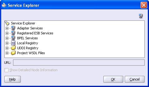
Expand your new connection under Adapter Services, followed by adapters, and then applications.
The WSDL tree displayed in the Service Explorer dialog box lists any WSDL files you have created using Application Explorer. The WSDL tree is generated by a WSDL servlet, which is automatically deployed as part of the BPEL Server installation.
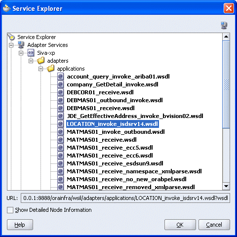
Select an outbound WSDL file that has been created using Application Explorer and click OK.
The WSDL File field in the Create Adapter Service dialog box displays the name and location of the selected WSDL file.
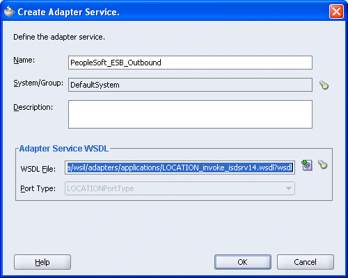
Click OK.
The new ESB project appears in the visual editor.
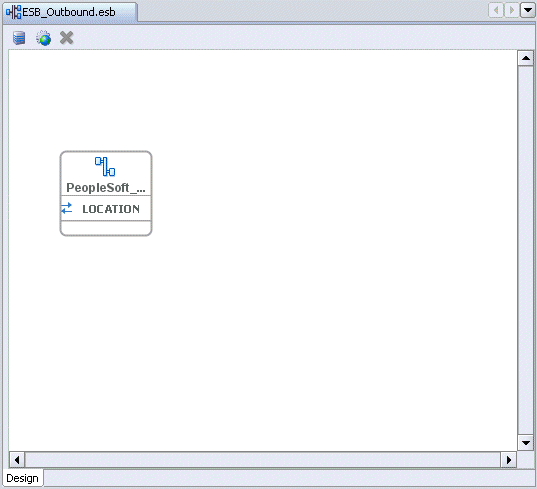
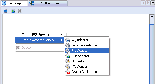
Creating a Read Process Operation Using the File Adapter
Right-click the ESB project in the middle pane, select Create Adapter Service followed by File Adapter.
The Create File Adapter Service dialog box is displayed.
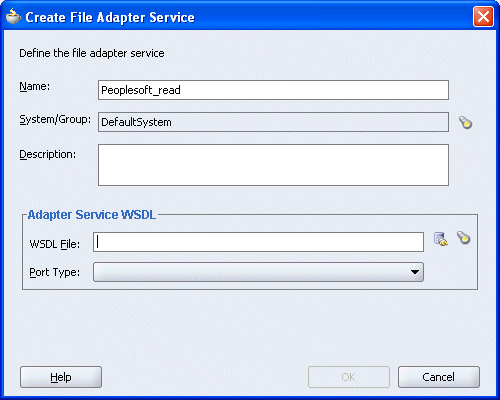
Enter a name for the File adapter and click the Configure adapter service wsdl icon next to the WSDL File field.
The Adapter Configuration Wizard - Welcome window is displayed.
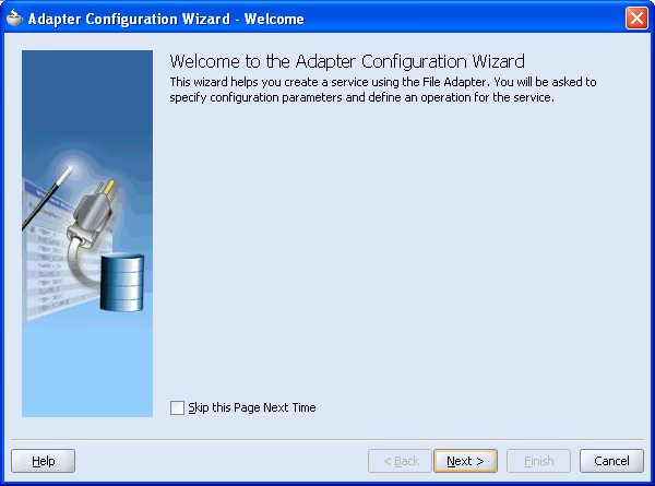
Click Next.
The Adapter Configuration Wizard - Step 1 of 6: Service Name window is displayed.
Click Next.
The Adapter Configuration Wizard - Step 2 of 6: Operation window is displayed.
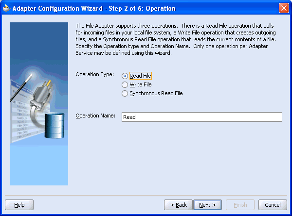
Click Read File as the Operation Type and click Next.
The Adapter Configuration Wizard - Step 3 of 6: File Directories window is displayed.
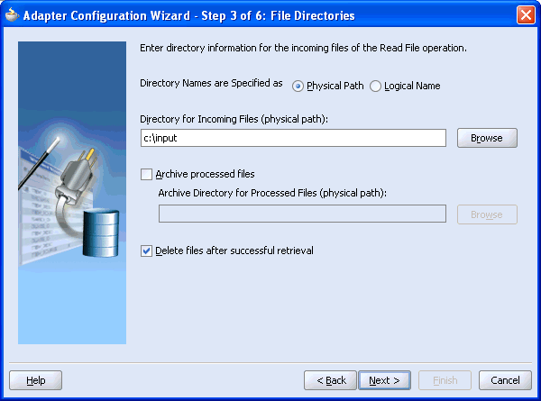
Enter the path of the input directory where you are placing the incoming XML file and click Next.
The Adapter Configuration Wizard - Step 4 of 6: File Filtering window is displayed.
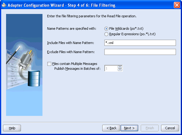
Enter the input file extension, for example *.xml, and click Next.
The Adapter Configuration Wizard - Step 5 of 6: File Polling window is displayed.
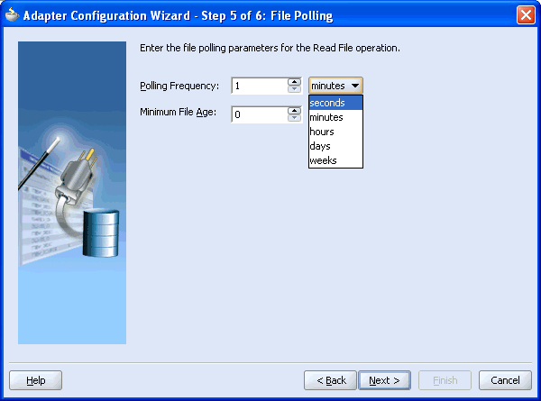
Change the Polling Frequency to seconds and click Next.
The Adapter Configuration Wizard - Step 6 of 6: Messages window is displayed.
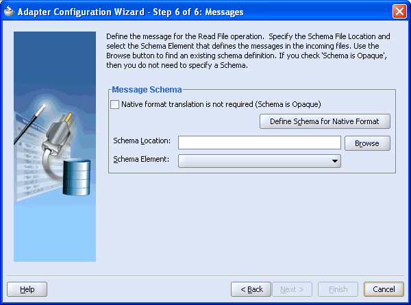
Click Browse to select the WSDL.
The Type Chooser window is displayed.
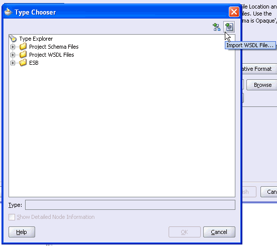
Click the Import WSDL File icon on the upper right corner of the dialog box.
The Import WSDL File dialog box is displayed.
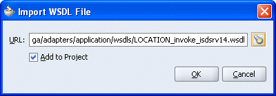
Select the WSDL file and click OK.
The Imported WSDL Files folder is added.
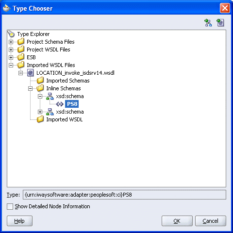
Expand the Imported WSDL Files folder, select an Inline Schema, for example, PS8, and click OK.
You are returned to the Adapter Configuration Wizard - Step 6 of 6: Messages window.
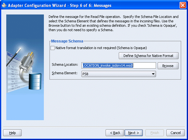
Click Next.
The Adapter Configuration Wizard - Finish window is displayed.
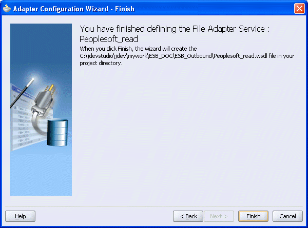
Click Finish.
You are returned to the Create File Adapter Service dialog box.
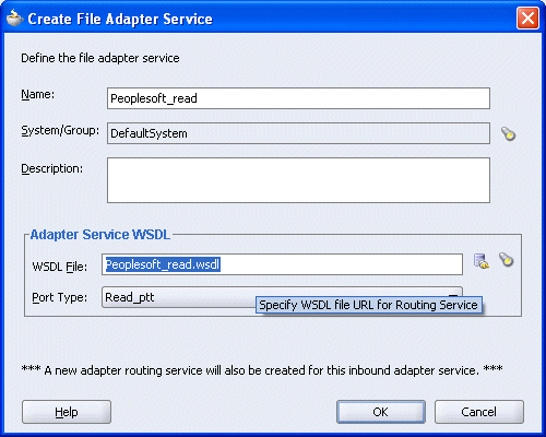
Click OK.
The Read operation with a routing service is added to the ESB outbound project view.
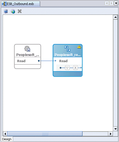
Providing a Routing Service for the Read Operation
Double-click the routing service.
The Routing Service window is displayed.
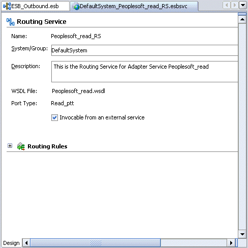
Expand the Routing Rules.
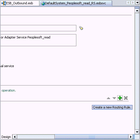
Click the green plus sign icon, which represents the option to Create a new Routing Rule.
The Browse Target Service Operation window is displayed.
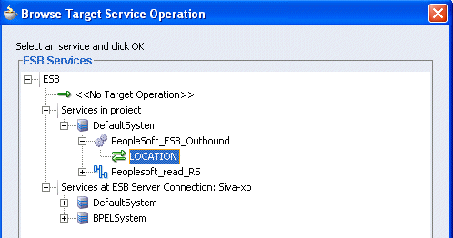
Expand Services in project, Default System, your adapter service node, for example, PeopleSoft_ESB_Outbound, and select the service name, for example, GetDetail.
Click OK.
You are returned to the Routing Rules window.
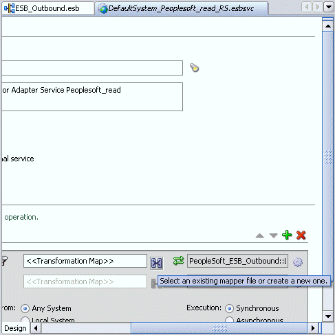
Click on the icon next to the <<Transformation Map>> field (Select an existing mapper file or create a new one).
The Request Transformation Map dialog box is displayed.
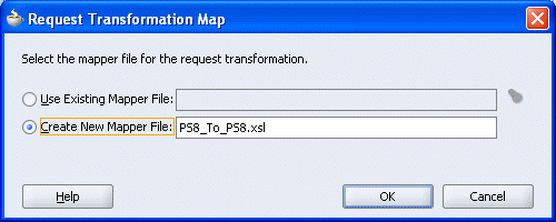
Select the Create New Mapper File option, specify the file name, and click OK.
The following mapping window is displayed.
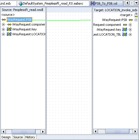
Select the WSDL file and map it to the Write operation.
Once you map the WSDL file, the Auto Map Preferences dialog box is displayed.
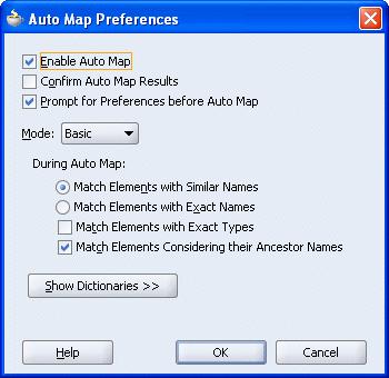
Click OK.
The mapping is completed as shown in the following window.
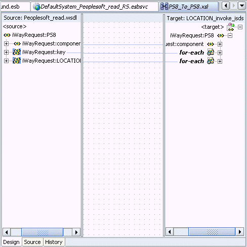
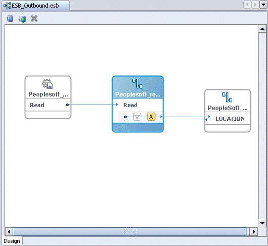
Double-click the ESB outbound project file in the left pane, for example, ESB_Outbound.esb.
Notice that the Routing service is now created for the Read operation.
Creating a Write Process Operation Using the File Adapter
Right-click the ESB project in the middle pane, select Create Adapter Service followed by File Adapter.

The Create File Adapter Service dialog box is displayed.
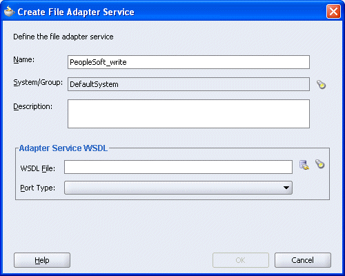
Enter a name for the File adapter and click the Configure adapter service wsdl icon next to the WSDL File field.
The Adapter Configuration Wizard - Welcome window is displayed.

Click Next.
The Adapter Configuration Wizard - Step 1 of 4: Service Name window is displayed.
Click Next.
The Adapter Configuration Wizard - Step 2 of 4: Operation window is displayed.
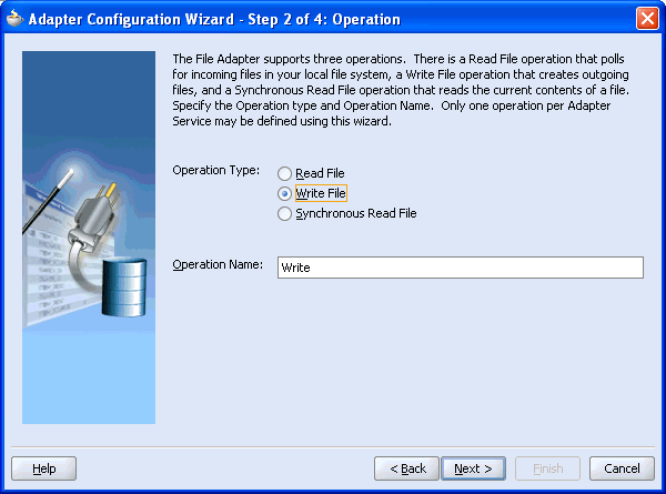
Click Write File as the Operation Type and click Next.
The Adapter Configuration Wizard - Step 3 of 4: File Configuration window is displayed.
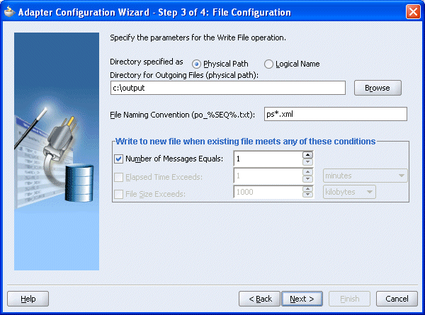
Enter the path of the output directory and name of the output file and click Next.
The Adapter Configuration Wizard - Step 4 of 4: Messages window is displayed.
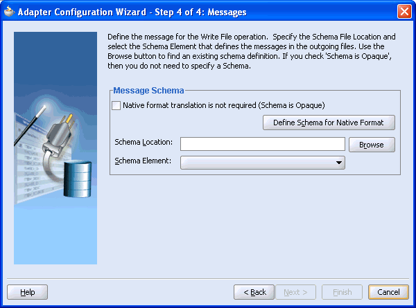
Click Browse to select the WSDL.
The Type Chooser window is displayed.
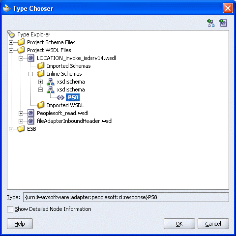
Expand the Project WSDL Files folder, select an Inline Schema and click OK.
You are returned to the Adapter Configuration Wizard - Step 4 of 4: Messages window.
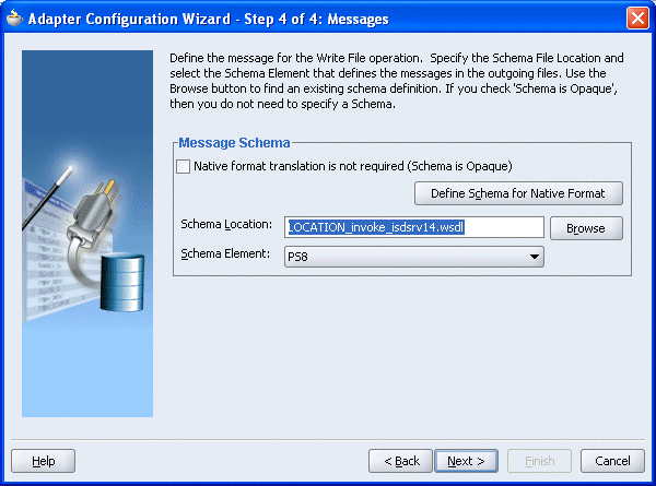
Click Next.
The Adapter Configuration Wizard - Finish window is displayed.
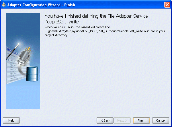
Click Finish.
You are returned to the Create File Adapter Service dialog box.
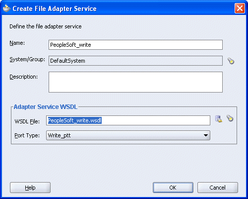
Click OK.
The Write operation is added to the ESB outbound project view.
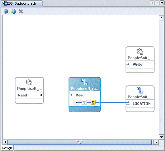
Providing a Routing Service for the Write Operation
Double-click the routing service.
The Routing Service window is displayed.
Expand the Routing Rules.
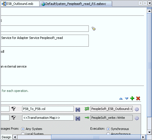
Click on the icon next to the <<Target Operation>> field (Browse for target service operations).
The Browse Target Service Operation window is displayed.
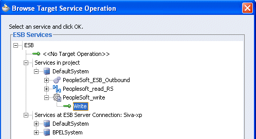
Expand Services in project, Default System, your adapter service node, for example, PeopleSoft_ESB_Outbound, and select the service name, for example, Write.
Click OK.
You are returned to the Routing Rules window.

Click on the icon next to the <<Transformation Map>> field (Select an existing mapper file or create a new one).
The Reply Transformation Map dialog box is displayed.
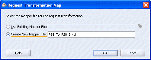
Select the Create New Mapper File option, specify the file name, and click OK.
The following mapping window is displayed.
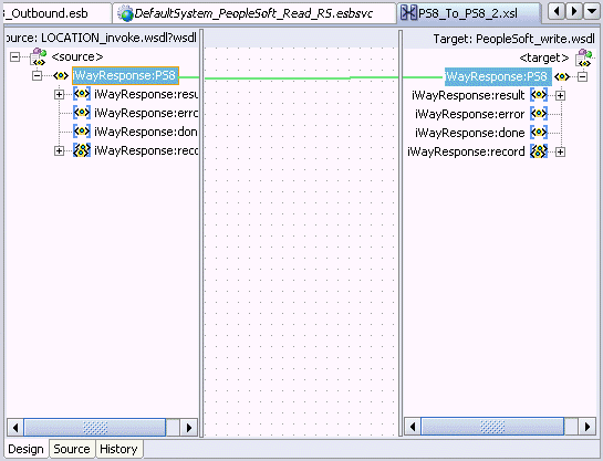
Select the WSDL file and map it to the Write operation.
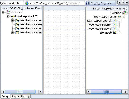
Once you map the WSDL file, the Auto Map Preferences dialog box is displayed.

Click OK.
The mapping is completed as shown in the following window.
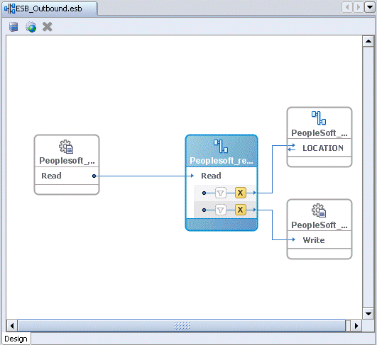
Double-click the ESB outbound project file in the left pane, for example, ESB_Outbound.esb.
Notice that the Routing service is now created for the Write operation.
Deploying the Project
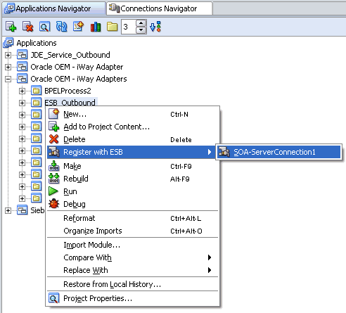
Right-click the created project, for example, ESB_Outbound, select Register with ESB, and the server connection, for example, ServerConnection1.
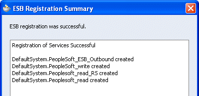
After successful deployment, the Registration of services Successful message is displayed.
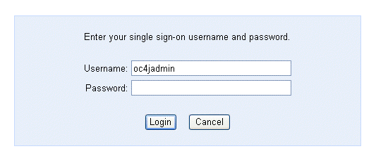
Logon to the ESB Control console to check whether the project has been successfully deployed.
The deployed process is listed under the Default System node.
Place the XML file in the folder that you specified during the creation of the Read operation.
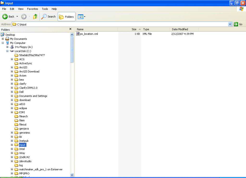
Check whether you are receiving the response in the output folder, which you have specified during the creation of the write operation and also the corresponding instance in the ESB Control console.
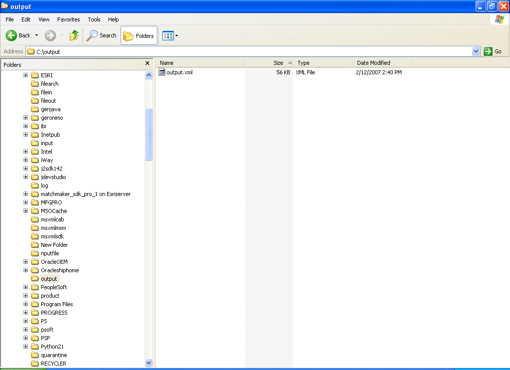
If the response is not received in the output folder, check the instance and the logs for the corresponding errors in the ESB Control console.
The following example describes how to configure an ESB inbound process to your PeopleSoft system, using an ESB project in Oracle JDeveloper.
Prerequisites
Before you proceed, you must create an inbound WSDL file for the adapter by using the following steps:
Create a target using Application Explorer.
Create a channel.
Create a WSDL file with the noport option.
Restart the Oracle Application Server.
Creating an Inbound ESB Project and Assigning an Inbound WSDL File
At the top of the upper left pane, click the Applications Navigator tab.

Right-click the application node you created and select New Project.
The New Gallery window is displayed.

From the Items list, select ESB Project and click OK.
The Create ESB Project dialog box is displayed.
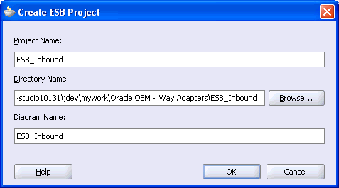
Perform the following steps:
Specify a name for the ESB project.
The Directory Name field and Diagram Name fields are updated automatically.
Click OK.
The ESB project is added at the top of the upper left pane.
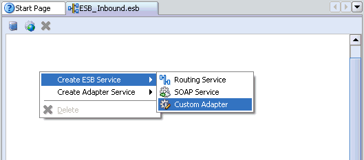
Right-click the ESB project in the middle pane, select Create ESB Service followed by Custom Adapter.
The Create Adapter Service dialog box is displayed.
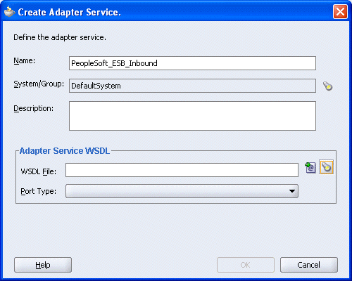
Enter a name for the adapter service and click the Service Explorer icon (second icon from the left preceding the WSDL File field).
The Service Explorer dialog box is displayed.

Expand your new connection under Adapter Services, followed by adapters, and then applications.
The WSDL tree displayed in the Service Explorer dialog box lists any WSDL files you have created using Application Explorer. The WSDL tree is generated by a WSDL servlet, which is automatically deployed as part of the BPEL Server installation.
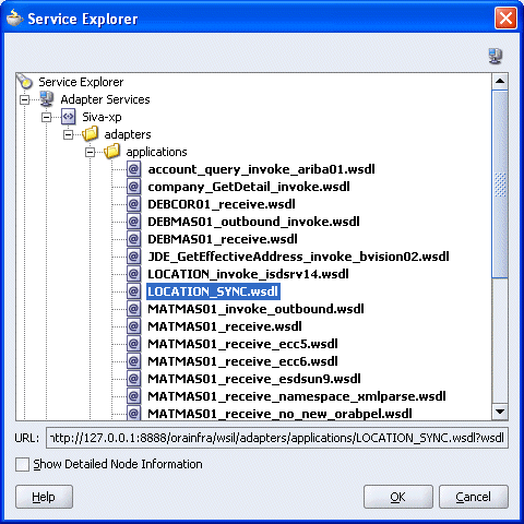
Select an inbound WSDL file that has been created using Application Explorer and click OK.
The WSDL File field in the Create Adapter Service dialog box displays the name and location of the selected WSDL file.
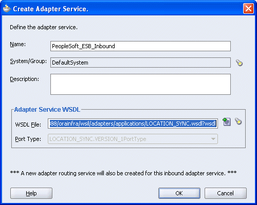
Click OK.
The new ESB project appears in the visual editor.
Creating a Write Process Operation Using the File Adapter
Right-click the ESB project in the middle pane, select Create Adapter Service followed by File Adapter.
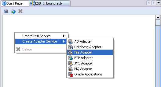
The Create File Adapter Service dialog box is displayed.
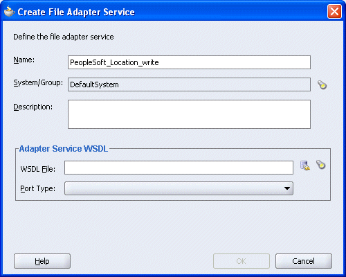
Enter a name for the File adapter and click the Configure adapter service wsdl icon next to the WSDL File field.
The Adapter Configuration Wizard - Welcome window is displayed.

Click Next.
The Adapter Configuration Wizard - Step 1 of 4: Service Name window is displayed.
Click Next.
The Adapter Configuration Wizard - Step 2 of 4: Operation window is displayed.

Click Write File as the Operation Type and click Next.
The Adapter Configuration Wizard - Step 3 of 4: File Configuration window is displayed.
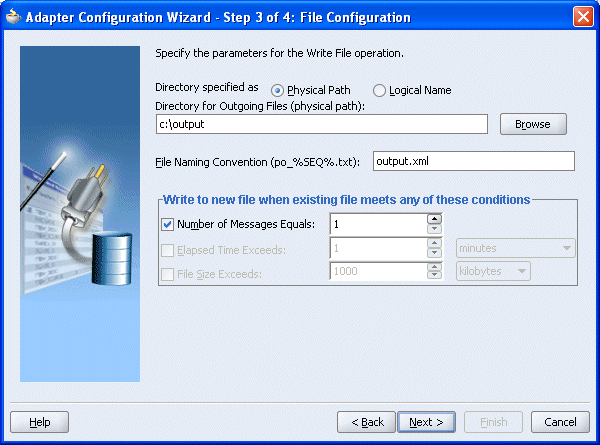
Enter the path of the output directory and name of the output file and click Next.
The Adapter Configuration Wizard - Step 4 of 4: Messages window is displayed.

Click Browse to select the WSDL.
The Type Chooser window is displayed.

Click the Import WSDL File icon on the upper right corner of the dialog box.
The Import WSDL File dialog box is displayed.
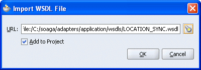
Select the WSDL file and click OK.
The Imported WSDL Files folder is added.
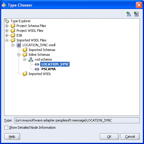
Expand the Imported WSDL Files folder, select an Inline Schema, for example, LOCATION_SYNC, and click OK.
You are returned to the Adapter Configuration Wizard - Step 4 of 4: Messages window.
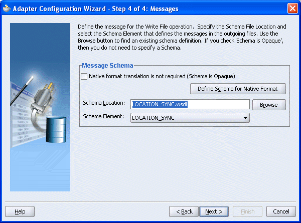
Click Next.
The Adapter Configuration Wizard - Finish window is displayed.
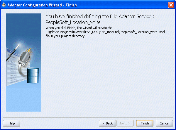
Click Finish.
You are returned to the Create File Adapter Service dialog box.
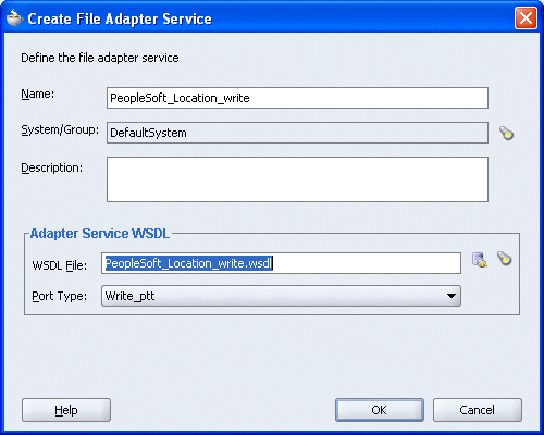
Click OK.
The Write operation with a routing service is added to the ESB inbound project view.
Providing a Routing Service for the Write Operation
Double-click the routing service.
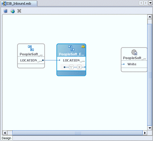
The Routing Service window is displayed.
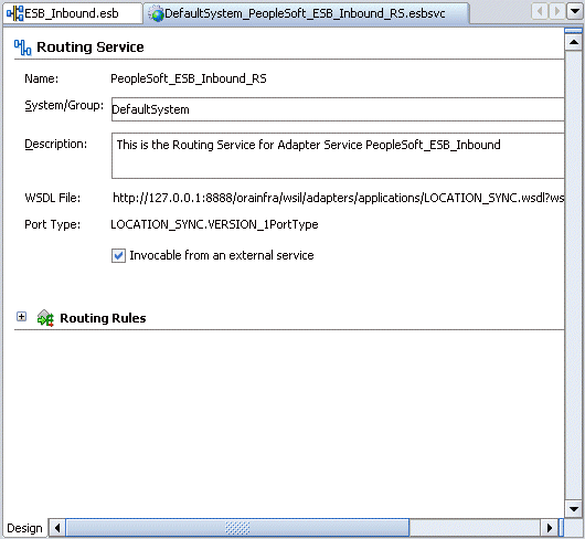
Expand the Routing Rules.
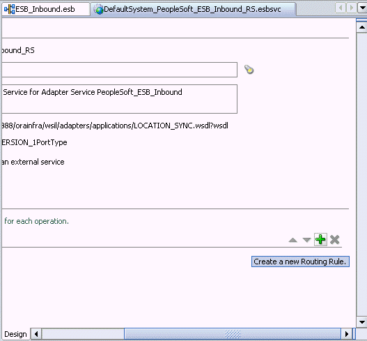
Click the green plus sign icon, which represents the option to Create a new Routing Rule.
The Browse Target Service Operation window is displayed.
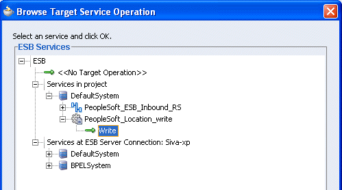
Expand Services in project, Default System, your adapter service node, for example, PeopleSoft_ESB_Inbound_RS, and select the service name, for example, Write.
Click OK.
You are returned to the Routing Rules window.
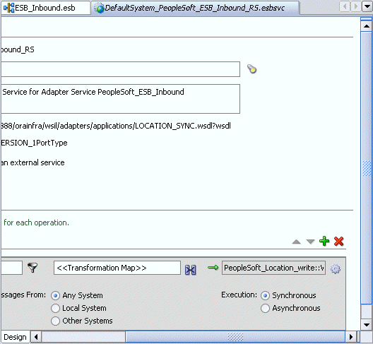
Click on the icon next to the <<Transformation Map>> field (Select an existing mapper file or create a new one).
The Request Transformation Map dialog box is displayed.
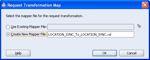
Select the Create New Mapper File option, specify the file name, and click OK.
The following mapping window is displayed.
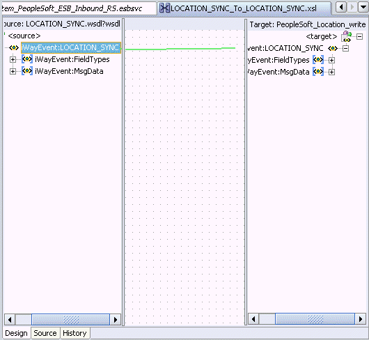
Select the WSDL file and map it to the Write operation.
Once you map the WSDL file, the Auto Map Preferences dialog box is displayed.

Click OK.
The mapping is completed as shown in the following window.
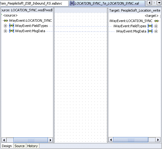
Double-click the ESB inbound project file in the left pane, for example, ESB_Inbound.esb.
Notice that the Routing service is now created for the Write operation in the middle pane.
Deploying the Project
Right-click the created project, for example, ESB_Outbound, select Register with ESB, and the server connection, for example, ServerConnection1.
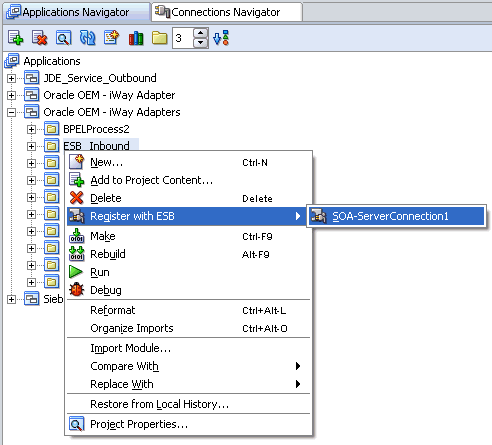
After successful deployment, the Registration of services Successful message is displayed.
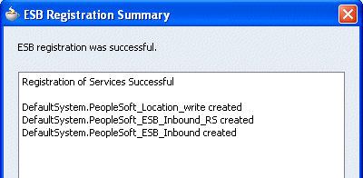
Logon to the ESB Control console to check whether the project has been successfully deployed.

The deployed process is listed under the Default System node.
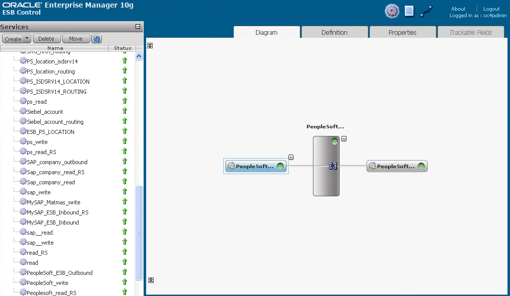
Trigger the event.
Check whether you are receiving the response in the output folder, which you have specified during the creation of the write operation.
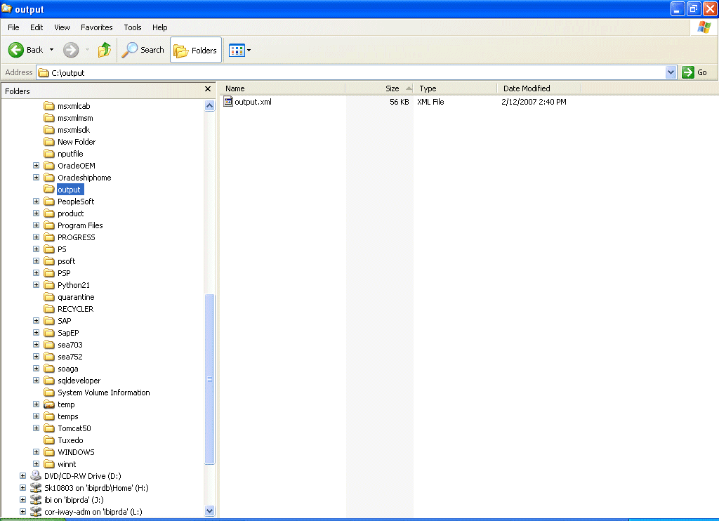
If the response is not received in the output folder, check the instance and the logs for the corresponding errors in the ESB Control console.