| Oracle® Warehouse Builder User's Guide 10g Release 2 (10.2.0.2) Part Number B28223-05 |
|
|
View PDF |
| Oracle® Warehouse Builder User's Guide 10g Release 2 (10.2.0.2) Part Number B28223-05 |
|
|
View PDF |
After you design mappings that define the operations for moving data from sources to targets, you can create and define process flows. Use process flows to interrelate mappings and activities external to Warehouse Builder such as email, FTP commands, and operating system executables.
You can use process flows to manage dependencies between mappings but not to schedule specifically when a given mapping should run. To schedule mappings, process flows, and other executable objects, see Chapter 28, "Scheduling ETL Objects".
This chapter contains the following topics:
A process flow describes dependencies between Warehouse Builder mappings and external activities such as email, FTP, and operating system commands.
Each process flow begins with a Start activity and concludes with an End activity for each stream in the flow. You can design a process flow to launch other process flows. Figure 7-1 shows an example of a process flow that launches a mapping MAP1. If the mapping completes successfully, Warehouse Builder sends an email notification EMAIL_SUCCEED and launches another process flow SUBPROC1. If the mapping fails, Warehouse Builder sends an email EMAIL_FAIL and ends the process flow.
When you design a process flow in Warehouse Builder, you use an interface known as the Process Flow Editor. Alternatively, you can create and define process flows using the Warehouse Builder scripting language, OMB Scripting Language as described in the Oracle Warehouse Builder API and Scripting Reference.
Process flow modules allow you to group process flow packages. Process flow packages, in turn, allow you to group process flows. Together, the process flow modules and packages provide two levels by which to manage and deploy process flows. You can validate, generate, and deploy process flows either at the module or the package level.
You can interrelate process flows contained within the same module. That is, you can design a process flow that launches other process flows so long as they are in the same module. For example, Figure 7-1 depicts a process flow PROC1 that includes process flow SUBPROC1. For PROC1 to run successfully, SUBPROC1 and PROC1 can be in the same or separate packages but must be contained within the same module.
You can copy process flows from one package to another package in the same or a different module and you can copy packages to a different module. To do so, use the Copy and Paste commands available under Edit on the Design Center main menu.
Deploying Process Flows to Workflow Engines
Warehouse Builder process flows comply with the XML Process Definition Language (XPDL) standard set forth by the Workflow Management Coalition (WfMC). When you generate a process flow, Warehouse Builder generates an XML file in the XPDL format. You can plug the generated XML file into any workflow engine that follows the XPDL standard.
Warehouse Builder is integrated with Oracle Workflow. From the Warehouse Builder Control Center described in Chapter 29, "Deploying Target Systems", you can deploy process flow packages or modules to Oracle Workflow.
To define a process flow, refer to the following sections:
Validating and Generating Process Flows.
Scheduling Process Flows (optional)
When you are satisfied that the process flow runs as expected, you can schedule the process flow to run on a single or multiple dates as described in Chapter 28, "Scheduling ETL Objects".
Deploying Process Flows as described in Chapter 29, "Deploying Target Systems".
Before working with process flows, create a process flow module. The module is a container by which you can validate, generate, and deploy a group of process flows. Process flow modules include process flow packages which include process flows.
To create a process flow module:
Right-click the Process Flow Modules node in the Project Explorer and select New.
Warehouse Builder displays the Welcome page for the Create Module Wizard.
Click Next.
On the Name and Description page, type a module name that is unique within the project. Enter an optional text description.
Click Next.
The wizard displays the Connection Information page.
You can accept the default location that the wizard creates for you based on the module name. Or, select an existing location from the drop down box. Click Edit to type in the connection information and test the connection.
Click Next.
The wizard displays the Finish page. Verify the name and deployment location of the new process flow module.
When you click Finish, Warehouse Builder stores the definition for the module and inserts its name in the Project Explorer, and prompts you to create a process flow package.
After you create a module for process flows, you can create the process flow package. The process flow package is an additional grouping mechanism from which you can deploy process flows.
To create a process flow package:
Right-click a process flow module in the Project Explorer and select New.
Warehouse Builder displays the Create Process Flow Package dialog.
Type a name and optional description for the process flow package.
If you intent to integrate with Oracle Workflow, please note that Oracle Workflow restricts package names to 8 bytes.
Select OK.
Warehouse Builder prompts you to create a process flow.
After you create a module and package for process flows, you can create the process flows.
To create a process flow:
Right-click a process flow package in the Project Explorer and select New.
Warehouse Builder displays the Create Process Flow dialog.
Type a name and optional description for the process flow.
Note for scheduling process flows: If you intend to schedule the execution of a process flow as described in Chapter 28, "Scheduling ETL Objects", there is an additional consideration. For any ETL object you want to schedule, the limit is 25 characters for physical names and 1995 characters for business names. Follow this additional restriction to enable Warehouse Builder to append to the process flow name the suffix _job and other internal characters required for deployment and execution.
Select OK.
Warehouse Builder launches the Process Flow and displays the process flow with a Start activity and an End_Success activity.
You can now model the process flow with activities and transitions.
Continue with the steps listed in "Instructions for Defining Process Flows".
After you create a process flow module and package, use the Process Flow Editor to design and edit process flows. The Process Flow Editor includes a variety of activities that you add and then connect with transitions to design a flow.
Activities represents units of work in a process flow. These units of work can involve components internal or external to Warehouse Builder.
Transitions indicate the sequence and conditions in which to launch activities.
Figure 7-2 shows the Process Flow Editor with a sample process flow. Activities display as icons on the canvas. In this example, the activities include a start, a mapping activity, 2 email activities, a subprocess, and two end activities. Arrows between the activities represent the transitions.
Standard Editor Components
The Process Flow Editor has the following standard components common to most editors in Warehouse Builder:
Title Bar: At the top of the editor, the title bar displays the name of the process flow. In Figure 7-2, the name is MY_PROC.
Menu Bar: Below the title bar, the menu bar provides access to the process flow editor commands.
Toolbar: Below the menu bar, the toolbar provides icons for commonly used commands.
Canvas: The canvas provides the work space where you design and modify process flows. When you first create a new process, the Process Flow panel displays with a Start activity and an End activity.
Palette: When you first launch a Process Flow Editor, Warehouse Builder displays the palette along the left side and it contains activity icons that you can drag and drop onto the canvas. You can relocate the palette anywhere on the editor. You can choose to hide or display the palette by clicking on the collapse icon on the palette.
Indicator Bar: In the lower panel, under the Bird's Eye View panel and Canvas panel, you can see mode icons, indicators, and descriptions as shown in Figure 7-3.
Figure 7-3 Indicator Bar on the Process Flow Editor
In the left corner are Naming Mode, Rename Mode, Read/Write, and Validation Mode.
In the right corner are the percent zoom indicator and the navigation mode. In the preceding figure, the zoom level is at 100% and the navigation mode is set to Select Mode.
You can resize windows by placing your mouse on the border of the window, pressing the mouse button when the double sided arrow appears, and dragging your mouse to indicate the desired size.
You can move windows by placing you mouse at the center of its top border, pressing the mouse button when the cross hairs appear, dragging the mouse to the desired location, releasing the mouse button after Warehouse Builder displays the desired shape and location for the window.
To show or hide windows, select Window from the menu bar and either activate or deactivate the check mark corresponding to the window.
Explorer
When you first launch the editor, Warehouse Builder displays an explorer for the editor in the upper left corner. The explorer provides a tree listing of all the activities on the canvas and their parameters. When you select an activity on the canvas, Warehouse Builder navigates to the activity on the explorer.
Object Details
When you first launch the editor, Warehouse Builder displays the object details on the left side. This window displays the properties for all activities and their parameters. Select an activity either from the canvas or the explorer and Warehouse Builder displays its properties. From the explorer, if you select an activity parameter, the object details window displays the properties for that parameter. You can edit properties displayed with a white background but not a grey background.
Bird's Eye View
Use the Bird's Eye View window to navigate large and complex process flows.
To display the Process Flow Editor:
From Process Flows on the Project Explorer, select a process flow module. If no process flow modules are listed, create a process flow module as described in "Creating Process Flow Modules".
Select a process flow package from a process flow module. If no process flow packages are listed, create a process flow package as described in "Creating Process Flow Packages".
Select a process flow from the Project Explorer as shown in Figure 7-4. If no process flows are listed in the process flow package, right-click the process flow package and select Create Process Flow.
Warehouse Builder prompts you to name the process flow and then launches the editor for you.
Figure 7-4 Process Flow in the Project Explorer
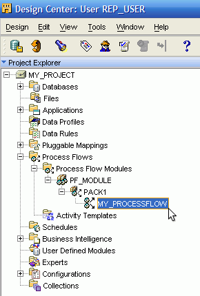
To open an existing process flow, double-click the process flow in the Project Explorer.
Or, select a process flow and then from the Edit menu, select Open Editor. Or, select a process flow and type Ctrl and the letter O. Or, right-click a process flow, and select Open Editor from the pop-up menu.
Warehouse Builder displays the Process Flow Editor in the Select mode.
The Process Flow Editor includes a variety of tools to assist you in navigating, selecting, and viewing objects on the canvas. Commands you use frequently when designing Process Flows include the following:
Select mode
Use the select mode to select objects on the canvas. When you select an activity, the editor displays a blue border around the activity and you can edit, move, or delete the activity.
You can edit the activity using the object details window in conjunction with the Available Objects tab in the editor explorer window. When you select a transition, the editor changes the arrow from black to blue. Edit the transition in the object details.
To activate the Select mode, click the icon in the toolbar or select Edit and Select Mode from the menu.
Edge Navigation
Edge navigation assists you in navigating complex designs on the canvas. Select the icon from the menu bar and then select a activity on the canvas. When you release the mouse button, Warehouse Builder navigates to the next activity in the flow and moves the focus to that activity. To navigate backward through a flow, select the edge navigation icon and then select the last activity in the flow.
Note:
If you used the Process Flow Editor in Warehouse Builder 10g Release 1 and previous releases, you may recognize the icon for edge navigation in this release is the same as was used for the create transition icon. In the Process Flow Editor and the Expert Editor, the create transition icon is no longer required or available.For navigating and displaying complex designs in the editor, you may find the following tools useful:
Pan
Interactive zoom
Zoom in
Zoom out
Fit in Window
Auto layout
Center
Expand Child Graph
Visit Child Graph
Return to Parent Graph
The basic design elements for process flows include activities and transitions. Activities represent units of work for the process flow such launching a mapping or verifying the existence of a file on a drive or directory. When you design a process flow in Warehouse Builder, you select activities from the editor palette, drag them onto the canvas, and set their parameters. Warehouse Builder includes the following types of activities:
Oracle Warehouse Builder Specific Activities: These activities enable you to launch Warehouse Builder objects such as mappings, transformations or other process flows. The process flow executes the object and issues a commit statement.
Utility Activities: These activities enable you to perform services such as send emails and transfer files.
Control Activities: These activities enable you to control the progress and direction of the process flow. For instance, use the Fork activity to launch multiple activities concurrently.
For the utility and control type activities, you can reuse their parameters by defining activity templates as described in "Creating and Using Activity Templates". For emails for example, use an email template to specify the SMTP server name and port number, the list of addresses, and the priority. Then you can reuse that template when you add email activities to a process flow.
For a description of each activity, see "Using Activities in Process Flows".
To add an activity to a process flow:
View the activities listed in the palette located along the left side of the editor.
By default, the palette lists all activities. To find a particular activity, use the list box on the palette to narrow the displayed list to one of the following types of activities: Oracle Warehouse Builder Specific Activities, Utility Activities, and Control Activities.
Select an activity from the palette and drag it onto the canvas.
The editor displays the activity on the canvas with the name highlighted in blue.
To accept the default name, press Enter. To change the name, type in the new name.
The editor lists the activity on the explorer window located at the left side of the editor and in the object details window along the left side.
In Object Details, enter the parameters for the activity.
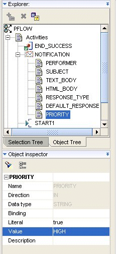
These parameters vary according to the type of activity. Figure 7-5, for example, shows the parameters for a notification activity which includes performer, subject, text_body, priority, and so on.
For each parameter, Warehouse Builder defines a read only Name, Direction, and Data Type. And for each parameter, you can specify values for Binding, Literal, Value, and Description.
Figure 7-5 The Parameters for a Notification Activity
Each parameters has the following properties:
Name
The name of the activity parameter, such as PRIORITY in Figure 7-5. For information about a specific parameter, look up the activity by name under "Using Activities in Process Flows".
Direction
The parameter direction is read-only for parameters that are not created by the user. A direction of IN indicates that the parameter is an input parameter for the activity.
Data Type
The parameter data type is read-only for parameters that are not created by the user. Warehouse Builder assigns the appropriate data type for all default parameters.
Binding
Use binding to pass in parameters from outside the process flow for parameters that are not created by the user. If you assign a parameter in Binding, it overrides any text you assign to Value.
Literal
If you type in a value for the parameter in the field Value, indicate whether the value is literal or an expression. The literal data types follow the PL/SQL literal value specification except for calendar data types. These data types are represented in a standard format as the Process Flow interacts with data sources from different locations. Table 7-1 provides the Literal Value Type, Format, and Example.
Table 7-1 Example of Literal Value Types
| Literal Value Type | Format | Example |
|---|---|---|
|
DATE |
YYYY-MM-DD |
2006-03-21 |
|
DATE |
YYYY-MM-DD HH24:MI:SS |
2006-03-21 15:45:00 |
|
TIMESTAMP |
YYYY-MM-DD HH24:MI:SS.FF9 |
2006-03-21 15:45:00.000000000 |
|
TIMESTAMP_TZ |
YYYY-MM-DD HH24:MI:SS.FF9 TZH:TZM |
2006-03-21 15:45:00.000000000 +01:00 |
|
YMINTERVAL |
[+-]YYYYYYYYY-MM |
+000000001-01 |
|
DMINVERVAL |
[+-]DDDDDDDDD HH24:MI.SS.FF9 |
+000000001 01:01:01.000000001 |
Value
This is the value of the parameter. For some parameters such as PRIORITY in Figure 7-5, Warehouse Builder enables you to select from a list of values. For other parameters, Warehouse Builder assigns default values which you can override by typing in a new value or using the field Binding. In the absence of a list of possible values or a default value, you must type in a value.
Description
You can type an optional description for each property.
In designing process flows you may want to reuse existing activities. For example, each time a mapping fails in a process flow, you may want to send an email to the same group of administrators. You create a template for the email activity once and then use and edit the activity in many process flows.
To create an activity template:
In the Project Explorer, navigate to the Activity Templates node under the Process Flows node.
To create a folder for containing templates, right-click the Activity Templates node and select New.
Assign a name for the folder.
Consider creating a folder for each type of template you plan to create. For instance, you could create separate folders to contain email and ftp templates.
The Create Activity Template Wizard will appear.
Note:
If the wizard does not appear automatically, then right-click a folder and select New.Follow the prompts in the Create Activity Template Wizard to complete the Name and Description Page, the Parameters Page, and the wizard summary page.
See "Using Activity Templates" for instructions on how to use the template in a process flow.
The rules for naming objects in the Activity Template depend on the naming mode you select in "Naming Preferences". Warehouse Builder maintains a business and a physical name for each object in the repository. The business name is its descriptive business name. The physical name is the name Warehouse Builder uses when generating code.
When you name objects while working in one naming mode, Warehouse Builder creates a default name for the other mode. Therefore, when working in the business name mode, if you assign a activity template name that includes mixed cases, special characters and spaces, Warehouse Builder creates a default physical name for you.
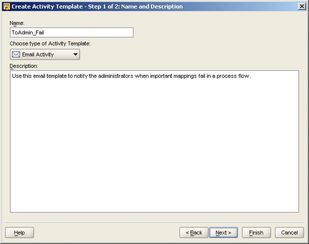
Assign a name and select the type of activity template you want to create. Also, write an optional description for the template.
Naming Activities
In the physical naming mode, a Activity name can be from 1 to 30 alphanumeric characters and blank spaces are not allowed. In the business naming mode, the limit is 2000 characters and blank spaces and special characters are allowed. In both naming modes, the name should be unique across the project.
Describing Activities
The description can be between 2 and 2,000 alphanumeric characters and can contain blank spaces. Specifying a description for a activity template is optional.
The following activity templates are available from the drop down menu.
Assign
FTP
File Exists
Manual
Notification
Set Status
Sqlplus
User Defined
Wait
Figure 7-6 shows an example of the Name and Description page for an email activity template.
Figure 7-6 Describing an Email Activity Template
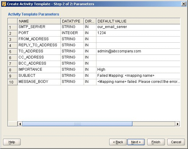
The wizard displays parameters based on the type of activity you previously selected: Assign, Manual, Email, File Exists, Data Auditor, FTP, Notification, Set Status, Sqlplus, User Defined, While Loop, Wait, or Notification activity.
Enter default values for the activity. When you use the activity template in a process flow, you can accept or edit the default values. In Figure 7-7, for example, you could edit the default values for the email subject and message body to contain the name of the mapping.
Figure 7-7 Parameters Page for Email Activity Template
Complete the following steps to use an activity template:
In the Project Explorer, navigate to the process flow module under the Process Flows node.
To open the Process Editor, right-click the Process Flow module and select Open Editor.
In the Process Editor, click the Available Objects tab in the explorer window and expand the Activity Templates as shown in Table 7-1.
Figure 7-8 Explorer Window with an Activity Template selected
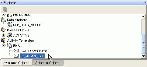
Drag and drop the activity template onto the canvas.
Activity templates in a process flow behave like regular activities.
To edit the activity, be sure to click the Selected Objects tab in the explorer window and then edit the activity in the object details window as shown in Figure 7-9.
Use transitions to indicate the sequence and conditions in which activities occur in the process flow. You can use transitions to execute an activity based on the completion state of the preceding activity.
When you add a transition to the canvas, by default, the transition has no condition applied to it. The process flow continues once the preceding activity completes, regardless of the ending state of the previous activity.
A transition with no condition applied to it has different semantics depending on the source activity type. If the activity type is FORK, then it may have multiple unconditional transitions in which each transition begins a new flow in the process flow. If the source activity type is not a FORK, then there may be only one unconditional transition and it is used when no other conditional transition is activated, like the final "ELSE" in an "IF...THEN...ELSIF...ELSE...END" PL/SQL statement.
For a transition to be valid, it must conform to the following rules:
All activities, apart from START and END, must have at least one incoming transition.
Only the AND and OR activities can have more than one incoming transition.
Only a FORK activity can have more than one unconditional outgoing transition.
A FORK activity can have only unconditional outgoing transitions
An activity that has an enumerated set of outcomes must have either an outgoing transition for each possible outcome or an unconditional outgoing transition.
An activity can have zero or more outgoing complex expression transitions.
An activity with an outgoing complex expression transition must have an unconditional outgoing transition to act as an otherwise.
An END_LOOP transition must have only one unconditional transition to its associated FOR_LOOP or WHILE_LOOP activity.
The transition taken by the "exit" outcome of a FOR_LOOP or WHILE_LOOP must not connect to an activity that could be executed as a result of the "loop" outcome.
To create dependencies using transitions:
When working in the select mode, place your mouse along the right border of the activity icon at its center line.
The editor displays the cursor as a small horizontal arrow, indicating that you can now use the mouse button to connect activities.
Press the left mouse button and scroll towards the next activity. As you begin to scroll, the cursor appears as an arrow with a plus sign beneath it. Continue to scroll towards the next activity until the plus sign under the cursor arrow changes to a circle. Release the mouse button to connect the two activities.
The editor displays an arrow between the two activities, assigns a default name to the transition, and displays the transition in the explorer and object selector windows.
In the object selector window, view or edit the following attributes:
Name: The editor assigns a default name which you can change.
Description: You can type an optional description for the transition.
Condition: Transitions you initially draw on the canvas are unconditional by default. To override the default and apply conditions, click the button in the Condition as described in "Defining Transition Conditions". If you select a condition, the editor displays the associated icon imposed onto the transition line on the canvas.
Source: This property is read-only and indicates the first activity in the connection.
Target: This property is read-only and indicates the second activity in the connection.
Some activities such as Sqlplus require additional configuration. These configuration details for a given activity are listed in Chapter 22, "Using Activities in Process Flows".
Process Flows and activities support the PL/SQL parameter passing concept, allowing data to be passed and so encouraging reuse through parameterization. This is accomplished through data stores, which are implemented as either parameters or variables.
Parameters allow the passing of data between a Process Flow and its activities or subprocesses.
Variables allow the storage of transient data, which is then maintained for the lifetime of the Process Flow execution. Variables are the main mechanism by which data can be passed between activities.
Process Flows implement a Scope hierarchy which allows the data to be passed between data stores. Figure 7-10 shows the direction in which the data is passed.
Figure 7-10 Relationship between the scope and the direction in which the data is passed
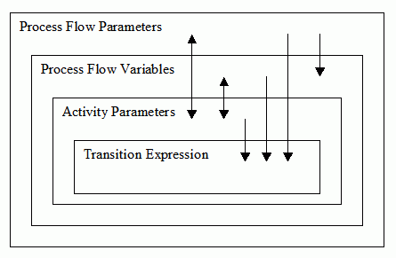
Process Flows follows the following rules for a scope hierarchy:
Process Flow variables can be initialized from flow parameters, but the reverse is not allowed
Activity parameters can pass data bi-directionally between process flow variables and process flow parameters.
Transition expressions can be evaluated against their source activity parameters and process flow parameters and process flow variables.
A data store cannot be accessed from another data store within the same scope.
The namespace allows a data store of an inner scope to hide the data store of an outer scope, similar to PL/SQL. By qualifying the data store name with the process flow name or activity, the hidden data store name can be referenced. For Example:
My_PROC.VAR1
The namespace does not allow referencing of data from another data store within the same scope.
A data store may be bound to another data store in an outer scope, which supports the passing of data in both directions.
Process Flow bindings follow the same semantics as PL/SQL with the following rules:
All the data is passed within the Process Flow by value.
Variables can be initialized through a binding; they cannot return a value back.
An INOUT parameter can be bound to an IN parameter in an outer scope. The output value, which is passed by value, is audited and then discarded.
As you can see in Figure 7-10, a variable may not pass data out to a Process Flow parameter, therefore this is accomplished by the use of an Assign operator, which can be bound to the variable and the parameter.
Oracle Warehouse Builder supports the evaluation of PL/SQL expressions for the derivation of parameters values and the evaluation of 'complex expression' transitions.
The expression must yield a correctly typed value for data store. Automatic conversion from VARCHAR is supported. Where the expression is associated with a transition then a BOOLEAN result is expected.
During evaluation, an expression will have access to the outer scopes which enclose it, therefore an expression for an activity's parameter will be able to use process flow variables and process flow parameters in its evaluation.
Warehouse Builder also makes additional data values available to the expression from the current activity and the owning Process Flow. Table 7-2 lists these values.
Table 7-2 Global Expression Values
| Identifier | Type | Description |
|---|---|---|
|
NUMBER_OF_ERRORS |
NUMBER |
Number of errors reported on completion of activity's execution. |
|
NUMBER_OF_WARNINGS |
NUMBER |
Number of warnings reported on completion of activity's execution. |
|
RETURN_RESULT |
VARCHAR2(64) |
Textual representation of result. For example, 'SUCCESS', 'WARNING', 'ERROR'. |
|
RETURN_RESULT_NUMBER |
NUMBER |
Enumeration of RESULT_RESULT1 = SUCCESS2 = WARNING3 = ERROR. |
|
RETURN_CODE |
NUMBER |
Integer 0-255, specific to activity, synonymous with an Operating System return code. |
|
PARENT_AUDIT_ID |
NUMBER |
The audit id of the calling Process Flow. |
|
AUDIT_ID |
NUMBER |
The audit id of the activity. |
The following additional constants are also provided:
| Identifier | Type | Description |
|---|---|---|
| SUCCESS | NUMBER | SUCCESS enumerated value. |
| WARNING | NUMBER | WARNING enumerated value. |
| ERROR | NUMBER | ERROR enumerated value. |
Use the Transition Editor to specify one of the enumerated conditions or write an expression for a complex condition. The enumerated conditions include success, warning, and error and display on the canvas as shown in Table 7-3.
Table 7-3 Types of Conditions for Transitions
| Icon | Transition | Description |
|---|---|---|
|
Success |
The process flow continues only if the preceding activity ends in success. |
|
|
Warning |
The process flow continues only if the preceding activity ends with warnings. |
|
|
Error |
The process flow continues only if the preceding activity ends in error. |
|
 |
Warning |
The process flow continues only if the preceding activity ends with warnings. |
|
Complex |
The process flow continues only if the preceding activity returns a value that meets the criteria you specify in an expression. |
|
 |
Extended |
The process flow continues only if the proceeding notification activity ends with an extended result. |
Extended transition is only valid for Notification activities because they are the only activity which return an extended result. The activity acquires this icon when set to an outcome of #MAIL, #NOMATCH, #TIE, #TIMEOUT. Table 7-4 list the output and the description of the Extended transition.
Table 7-4 Output and Description of the Extended Transition
| Output | Description |
|---|---|
|
#NOMATCH |
Result of a voting notification where no candidate acquired the minimum number of votes to win |
|
#TIE |
Result of a voting notification where the result was a tie. |
|
|
A mail error occurred for the notification. Some recipients did not receive it and so it was cancelled. |
|
#TIMEOUT |
The notification did not receive a response within the configured amount of time. |
If the activity has only one outgoing activity, you can specify any of the conditions listed in Table 7-3 or leave the transition unconditional.
The rules for using multiple outgoing transitions depend on the type of activity. The general rule is that you can use an unlimited number of complex conditions in addition to one of each of the following: SUCCESS, WARNING, ERROR, and UNCONDITIONAL. The exception to this rule comes when you use control activities such as AND, FORK, and OR.
When you add multiple outgoing transitions from an activity, ensure that the conditions do not conflict. A conflict occurs when the process flow logic can evaluate to more than one outgoing transition being true.
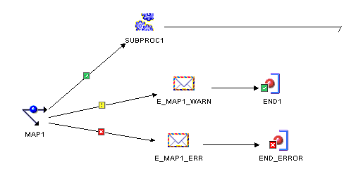
Figure 7-11 shows a portion of a process flow in which different activities are triggered based on the three possible completion states of MAP1. Since only one of these conditions can be satisfied at a time, there is no conflict. If you attempt to add an unconditional transition or another conditional transition, two transition conditions would be true and the process flow would be invalid.
Figure 7-11 Outgoing Transition Conditions
The PL/SQL expression is executed in the context of the Control Center user that requested the execution of the activity. However in the case where the Oracle Workflow schema is hosted in a remote database instance then the effective user of the generate database link with be used instead. A different Control Center user may be selected but configuring the Process Flow and specifying an 'Evaluation Location'. Therefore the expression may reference any PL/SQL function that is accessible to the Control Center user.