| Oracle® Application Server Installation Guide 10g Release 3 (10.1.3.2.0) for Microsoft Windows Part Number B32197-01 |
|
|
View PDF |
| Oracle® Application Server Installation Guide 10g Release 3 (10.1.3.2.0) for Microsoft Windows Part Number B32197-01 |
|
|
View PDF |
This chapter provides an overview of the high availability configurations supported by Oracle Application Server and instructions for installation.
Contents of this chapter:
This chapter provides only a brief overview of the high availability configurations in Oracle Application Server. For a complete description of the configurations, see the Oracle Application Server High Availability Guide.
Oracle Application Server supports the following types of high availability configurations at installation time. Note that there are multiple variants of each type.
Section 6.1.1, "Active-Active Topologies: OracleAS Clusters"
Section 6.1.2, "Active-Passive Topologies: OracleAS Cold Failover Clusters"
For a quick summary of the high availability configurations, see Section 6.1.4, "Summary of Differences".
Oracle Application Server provides an active-active redundant model for all its components. In an active-active topology, two or more Oracle Application Server instances are configured to serve the same workload. These instances can run on the same machine or on different machines.The instances are front-ended by an external load balancer, which directs requests to any of the active instances. Instead of an external load balancer, you can also run a software load balancer to distribute the requests. In production environment, however, a hardware load balancer is recommended.
Common properties of an active-active topology include:
Similar instance configuration
The instances need to serve the same workload or applications. Some configuration properties should have similar values across instances so that the instances can deliver the same reply to the same request. Other configuration properties may be instance-specific, such as local host name information.
If you make a configuration change to one instance, you should also make the same change to the other instances in the active-active topology. The "Configuring and Managing Clusters" chapter in the Oracle Containers for J2EE Configuration and Administration Guide lists the files that contain properties that should be replicated.
Independent operation
If one Oracle Application Server instance in an active-active topology fails, the other instances in the cluster continue to serve requests. The load balancer directs requests only to instances that are alive.
Advantages of an active-active topology include:
Increased availability
An active-active topology is a redundant configuration. Loss of one instance can be tolerated because other instance can continue to serve the same requests.
Increased scalability and performance
Multiple identically-configured instances provide the capability to share a workload among different machines and processes. You can scale the topology by adding new instances as the number of requests increase.
For instructions on creating the OracleAS Clusters configuration, see Section 6.2, "Creating the Active-Active Topology".
Oracle Application Server provides an active-passive model for all its components in OracleAS Cold Failover Clusters. In an OracleAS Cold Failover Cluster topology, two Oracle Application Server instances are configured to serve the same application workload but only one is active at any particular time. The passive instance runs (that is, becomes active) only when the active instance fails. These instances run on nodes that are in a hardware cluster.
Common properties of an OracleAS Cold Failover Cluster topology include:
Hardware cluster
In an OracleAS Cold Failover Cluster topology, you run Oracle Application Server on machines that are in a hardware cluster, with vendor clusterware running on the machines.
You install the Oracle home for the Oracle Application Server instance on storage shared by the machines in the hardware cluster.
The active node in the OracleAS Cold Failover Cluster topology mounts the shared storage so that it has access to the Oracle home. If it fails, the passive instance mounts the shared storage and accesses the same Oracle home.
Virtual hostname
The virtual hostname gives clients a single system view of the Oracle Application Server middle tier. Clients use the virtual hostname to access the Oracle Application Server middle tier.
The virtual hostname is associated with a virtual IP. This name-IP entry must be added to the DNS that the site uses. For example, if the two physical hostnames of the hardware cluster are node1.mycompany.com and node2.mycompany.com, the single view of this cluster can be provided by the virtual hostname apps.mycompany.com. In the DNS, apps maps to a virtual IP address that floats between node1 and node2 via a hardware cluster. Clients access Oracle Application Server using apps.mycompany.com; they do not know which physical node is active and actually servicing a particular request.
You can specify the virtual hostname during installation. See the Oracle Application Server Installation Guide.
Failover procedure
An active-passive configuration also includes a set of scripts and procedures to detect failure of the active instance and fail over to the passive instance while minimizing downtime.
Advantages of an OracleAS Cold Failover Cluster topology include:
Increased availability
If the active instance fails for any reason or must be taken offline, an identically configured passive instance is prepared to take over at any time.
Reduced operating costs
In an active-passive topology only one set of processes is up and serving requests. Managing the active instance is generally easier than managing an array of active instances.
Application independence
Some applications may not be suited to an active-active topology. This may include applications that rely heavily on application state or on information stored locally. An active-passive topology has only one instance serving requests at any particular time.
For instructions on creating the OracleAS Cold Failover Cluster configuration, see Section 6.3, "Creating the Active-Passive Topology".
OracleAS Disaster Recovery configurations have the following characteristics:
A production site and a standby site that mirrors the production site. Typically, these sites are located some distance from each other to guard against site failures such as floods, fires, or earthquakes. During normal operation, the production site handles all the requests. If the production site goes down, the standby site takes over and handles all the requests.
Each site has all the hardware and software to run. It contains nodes for running Oracle Application Server instances, load balancers, and DNS servers.
For installation details, see Section 6.4, "Creating an OracleAS Disaster Recovery Configuration".
Table 6-1 summarizes the differences among the high availability configurations.
Table 6-1 Differences Among the High Availability Configurations
| OracleAS Cold Failover Cluster |
OracleAS Clusters |
OracleAS Disaster Recovery |
|
|---|---|---|---|
|
Node configuration |
Active-Passive |
Active-Active |
Active-Passive |
|
Hardware cluster |
Yes |
No |
Optional (hardware cluster required only if you installed the OracleAS Infrastructure in an OracleAS Cold Failover Cluster configuration) |
|
Virtual hostname |
Yes |
No |
Yes |
|
Load balancer |
No |
Yes |
No |
|
Shared storage |
Yes |
No |
No |
This section describes how to install Oracle Application Server in an active-active topology with OracleAS Clusters. OracleAS Clusters is one of the high availability environments supported by Oracle Application Server.
Contents of this section:
Section 6.2.2, "OracleAS Clusters in Active-Active Topologies"
Section 6.2.3, "Properties of Oracle Application Server Instances in Active-Active Topologies"
Section 6.2.4, "Installation Steps for Active-Active Topologies"
Section 6.2.5, "Supporting Procedures for Creating the Active-Active Topology"
An active-active topology consists of redundant Oracle Application Server instances that deliver greater scalability and availability than a single instance. Active-active topologies remove the single point of failure that a single instance poses. While a single Oracle Application Server instance leverages the resources of a single host, a cluster of Oracle Application Server instances spans multiple hosts, distributing application execution over a greater number of CPUs. A single Oracle Application Server instance is vulnerable to the failure of its host and operating system, but an active-active topology continues to function despite the loss of an operating system or a host, hiding any such failure from clients.
In active-active topologies, all the instances are active at the same time. This is different from active-passive topologies, where only one instance is active at any time.
The nodes in the active-active topologies are not in a hardware cluster.
Load Balancer Requirements
Active-active topologies use a load balancer to direct requests to one of the Oracle Application Server instances in the topology. In other words, the Oracle Application Server instances are fronted by the load balancer.
You configure the load balancer with virtual server names for HTTP and HTTPS traffic. Clients use the virtual server names in their requests. The load balancer directs requests to an available Oracle Application Server instance.
See the Oracle Application Server High Availability Guide for a list of features that your load balancer should have.
Shared Storage for Oracle Metadata Services (MDS)
In addition to the local drives on each node, you need a shared storage that can be accessed by all the nodes in an active-active topology. On the shared storage, you need to create a directory for Oracle Metadata Services (MDS). The MDS directory stores data about your deployed applications.
By having the MDS directory on the shared storage, you ensure that all Oracle Application Server instances access the same data and you do not have to worry about replicating the data.
The mount point for the MDS directory must be the same for all nodes in the active-active topology (for example, S:\oracle\mds).
You do not need the shared storage during installation, but you need it when you deploy your applications. You specify the path to the MDS directory during application deployment.
Figures of Active-Active Topologies
The following figures show two active-active topologies. The difference in the topologies is whether you install Oracle HTTP Server, Oracle WebCenter Framework, and Oracle Content DB in the same Oracle home or in separate Oracle homes.
Figure 6-1 shows an active-active topology with Oracle HTTP Server, Oracle WebCenter Framework, and Oracle Content DB in the same Oracle home. Figure 6-2 shows an active-active topology with Oracle HTTP Server, Oracle WebCenter Framework, and Oracle Content DB in separate Oracle homes.
Figure 6-1 Active-Active Topology with Oracle HTTP Server and WebCenter Suite in the Same Oracle Home
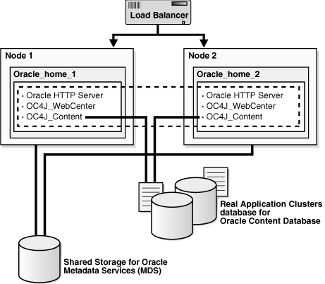
Figure 6-2 Active-Active Topology with Oracle HTTP Server, WebCenter Framework, and Oracle Content DB in Separate Oracle Homes
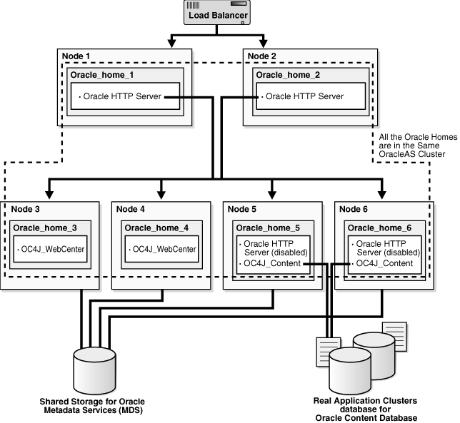
All the Oracle Application Server instances in an active-active topology belong to the same cluster. Oracle HTTP Server can forward application requests to any OC4J instance in the same cluster. This is useful because the WebCenter Framework and Oracle Content DB components run in OC4J containers:
Table 6-2 WebCenter Framework and Oracle Content DB and their OC4J Instances
| Component | Runs in this OC4J Instance |
|---|---|
|
WebCenter Framework |
OC4J_WebCenter |
|
Oracle Content DB |
OC4J_Content |
You can group instances in a cluster using one of the following ways:
All the instances use the same multicast IP address and port.
All the instances are chained to the same discovery server.
Each instance specifies all other instances in the opmn.xml configuration file.
If the instances run on nodes that are on different subnets, you have to designate a node to be the gateway server, which bridges the instances on the different subnets.
OracleAS Clusters also enable you to use the @cluster parameter in some opmnctl commands. Commands that use the @cluster parameter apply to all instances in the cluster. For example, you can use the @cluster parameter to start all components in all instances in the cluster.
OC4J instances in a cluster have the following features:
OC4J instances have cluster-wide properties as well as instance-specific properties. Cluster-wide properties are properties whose values should be similar for all OC4J instances in the cluster. Instance-specific properties are properties that have different values for each OC4J instance. For a list of cluster-wide properties, see the "Configuring and Managing Clusters" chapter in the Oracle Containers for J2EE Configuration and Administration Guide.
If you modify a cluster-wide property in one OC4J instance, you should propagate the change to all other OC4J instances in the cluster.
When you deploy an application to an OC4J instance, you also need to deploy it on all other OC4J instances in the cluster.
The number of OC4J processes is an instance-specific property: it can be different for each OC4J instance. This must be configured for each Oracle Application Server instance in the cluster. The OC4J process configuration provides flexibility to tune according to the specific hardware capabilities of the host. By default, each OC4J instance is instantiated with a single OC4J process.
For details, see the "Configuring and Managing Clusters" chapter in the Oracle Containers for J2EE Configuration and Administration Guide.
Because the load balancer can send a request to any Oracle Application Server instance in the topology, you need to ensure that the instances are configured in the same manner so that clients get the same response regardless of which instance handles the request. This includes the following:
Deploy the same applications on each OC4J instance in the topology.
Ensure that you replicate state and stateful session bean information across OC4J instances so that in the event that an OC4J instance fails, another OC4J instance contains the state information and can continue the session.
Ensure that configuration properties for all the OC4J instances in the topology are identical. These configuration properties are listed in chapter 8, "Configuring and Managing Clusters", in section "Replicating Changes Across a Cluster", in the Oracle Containers for J2EE Configuration and Administration Guide.
To create the topology shown in Figure 6-1 or Figure 6-2, you perform the following steps:
Step 1: Install a High Availability Oracle Database
Step 2: Install Oracle HTTP Server, Oracle WebCenter Framework, and Oracle Content DB and Cluster the Instances using OPMN
Step 3: Disable Oracle HTTP Server on Nodes with Oracle Content DB (Distributed Installations Only)
Step 4: Configure the Load Balancer with Virtual Server Names
Step 5: (optional) Configure SSL on Both Nodes
Step 6: Update Domain Properties for Oracle Content DB
Step 7: Reload OPMN
The following sections describe the steps in detail.
Step 1 Install a High Availability Oracle Database
You need a database for Oracle Content DB. In high availability topologies, you should use high availability databases, such as cold failover cluster database or Real Application Clusters database.
See Section 2.3, "Requirements for Oracle Content Database" for more information on database requirements for Oracle Content DB.
Step 2 Install Oracle HTTP Server, Oracle WebCenter Framework, and Oracle Content DB and Cluster the Instances using OPMN
You can install Oracle HTTP Server, Oracle WebCenter Framework, and Oracle Content DB in the same Oracle home (see Figure 6-1), or in different Oracle homes (see Figure 6-2).
For Oracle Application Server instances that you want to group in the same active-active topology, you need to place them in the same cluster. This enables communication between the Oracle HTTP Server and OC4J instances, and simplifies the management of Oracle Application Server instances. OracleAS Clusters enable you to use the @cluster parameter for the opmnctl command to manage all the instances in the cluster.
You can create clusters using one of the following methods:
Dynamic Discovery Method
In this method, each ONS node within the same subnet announces its presence with a multicast message. The cluster topology map for each node is automatically updated as nodes are added or removed, enabling the cluster to be self-managing.
If you use this method and you are performing a basic installation, you can define a cluster postinstallation by following the steps in Section 6.2.5.1, "Setting up Clusters with the Dynamic Discovery Method". If you use this method and you are performing an advanced installation, you should specify the multicast address and port on the Cluster Topology Configuration screen in the installer.
Discovery Server Method
In this method, specific nodes within a cluster are configured to serve as "discovery servers", which maintain the topology map for the cluster; the remaining nodes then connect with one another via this server.
If you use this method, you can define a cluster for OPMN by specifying the names of the Oracle Application Server instances explicitly in the opmn.xml file of each instance by following the steps in Section 6.2.5.2, "Setting up Clusters with the Discovery Server Method" after installation.
Gateway Method
This configuration is used to connect topologies separated by firewalls or on different subnets using specified "gateway" nodes.
If you use this method, see the section "Configuring Cross-Topology Gateways" in the Oracle Containers for J2EE Configuration and Administration Guide for configuration details.
You can perform either an integrated installation or a distributed installation.
For Integrated Installations (Oracle HTTP Server, Oracle WebCenter Framework, and Oracle Content DB in the Same Oracle Home)
You install Oracle Application Server on the local storage of each node in the active-active topology.
Perform a basic installation as described in Chapter 4, "Basic Installation"so that Oracle HTTP Server, Oracle WebCenter Framework, and Oracle Content DB will run from the same Oracle home.
Note the following:
Set the Oracle home to be on the local storage of each node.
For deployment to work across all instances in a cluster, the oc4jadmin password must be the same for all instances in the cluster.
To simplify administering the instances, use the same Oracle home path and the same instance name for each node.
If you are using the dynamic discovery method to cluster the Oracle Application Server instances for OPMN, be sure to perform the steps in Section 6.2.5.1, "Setting up Clusters with the Dynamic Discovery Method" after installation.
If you are using the discovery server method to cluster the Oracle Application Server instances for OPMN, be sure to perform the steps in Section 6.2.5.2, "Setting up Clusters with the Discovery Server Method" after installation.
If you are using the gateway method to cluster the Oracle Application Server instances for OPMN, see the section "Configuring Cross-Topology Gateways" in the Oracle Containers for J2EE Configuration and Administration Guide for configuration details.
For Distributed Installations (Oracle HTTP Server, Oracle WebCenter Framework, and Oracle Content DB in Different Oracle Homes)
You install Oracle Application Server on the local storage of each node in the active-active topology.
For the nodes where you want to run Oracle HTTP Server, follow the steps in Section 5.2.5, "Installing Oracle HTTP Server".
For the nodes where you want to run Oracle WebCenter Framework and Oracle Content DB, you must perform the following two installations on each node:
An advanced installation of Oracle WebCenter Framework, as described in Section 5.2.4, "Installing Oracle WebCenter Framework"
An advanced installation of Oracle Content DB, as described in Section 5.2.3, "Installing Oracle Content Database"
During installation, select the following options:
On the Administration Settings screen:
If you want this node to administer the cluster using Application Server Control, select Start Oracle Enterprise Manager 10g ASControl in this instance. In a cluster topology, only one instance should be configured as an Administration OC4J instance. Note that the Administration OC4J instance for the cluster does not have to be the first installed node.
If you do not want this node to administer the cluster, deselect Start Oracle Enterprise Manager 10g ASControl in this instance.
If you are using the dynamic discovery method to cluster the Oracle Application Server instances for OPMN, perform the following:
If you are installing Oracle HTTP Server, select Configure this Oracle HTTP Server instance to be part of an Oracle Application Server cluster on the "Cluster Topology Configuration" screen. Specify the IP Address and Port for the multicast address shared by all the nodes in the cluster.
If you are installing Oracle WebCenter Framework, select Configure this instance to be part of an Oracle Application Server cluster topology on the "Cluster Topology Configuration" screen. Specify the IP Address and Port for the multicast address shared by all the nodes in the cluster and select Access this OC4J Instance from a separate Oracle HTTP Server.
If you are installing Oracle Content DB, select Configure this instance to be part of an Oracle Application Server cluster topology on the "Cluster Topology Configuration" screen. Specify the IP Address and Port for the multicast address shared by all the nodes in the cluster.
Note that the multicast address must be between 224.0.1.0 and 239.255.255.255. If you are installing on the first node in the cluster, you may choose any IP address and port, as long as it falls in the multicast address range.
Note the following:
Set the Oracle home to be on the local storage of each node.
For deployment to work across all instances in a cluster, the oc4jadmin password must be the same for all instances in the cluster.
Ensure that the same component uses the same port number in each Oracle Application Server instance in the cluster. For example, ensure that Oracle HTTP Server is listening at the same port number for all instances in the cluster.
To simplify administering the instances, use the same Oracle home path and the same instance name for each node.
If you are using the discovery server method to cluster the Oracle Application Server instances for OPMN, be sure to perform the steps in Section 6.2.5.2, "Setting up Clusters with the Discovery Server Method" after installation.
If you are using the gateway method to cluster the Oracle Application Server instances for OPMN, see the section "Configuring Cross-Topology Gateways" in the Oracle Containers for J2EE Configuration and Administration Guide for configuration details.
Step 3 Disable Oracle HTTP Server on Nodes with Oracle Content DB (Distributed Installations Only)
This step is required only if you performed a distributed installation in step 2.
Disable Oracle HTTP Server on the Oracle homes where you installed Oracle Content DB.
Set the status of Oracle HTTP Server to disabled in the ORACLE_HOME\opmn\conf\opmn.xml file:
<ias-component id="HTTP_Server" status="disabled">
Stop and restart all components in the Oracle home.
C:\> ORACLE_HOME\bin\opmnctl stopall
C:|> ORACLE_HOME\bin\opmnctl startall
Step 4 Configure the Load Balancer with Virtual Server Names
Refer to your load balancer documentation for configuration steps. On your load balancer, you need to configure a virtual server name and port for HTTP traffic, and another virtual server name and port for HTTPS traffic. The port numbers for the virtual server names should match the port numbers at which Oracle HTTP Server is listening. Clients will use the virtual server names and ports to access Oracle Application Server instances.
Step 5 (optional) Configure SSL on Both Nodes
This step is required only if you are using SSL.
Edit the ORACLE_HOME\Apache\Apache\conf\httpd.conf file on each node as follows:
Add the following line to the httpd.conf to load the certheaders_module.
LoadModule certheaders_module modules/ApacheModuleCertHeaders.dll
Add a virtual host directive.
<VirtualHost *:7777>
ServerName myworkplace.com
Port 443
ServerAdmin you@youraddress.com
RewriteEngine On
RewriteOptions inherit
SimulateHTTPS On
</VirtualHost>
Restart Oracle HTTP Server on all the nodes.
Step 6 Update Domain Properties for Oracle Content DB
Update these domain properties using Application Server Control on each node:
Set IFS.DOMAIN.APPLICATION.ApplicationHost to the virtual hostname configured on the load balancer.
Set IFS.DOMAIN.APPLICATION.ApplicationPort to the port number configured on the load balancer.
To edit these properties using Application Server Control:
On the Cluster Topology page, expand OC4J_Content.
Click content located under OC4J_Content. This displays the "Application: content" page.
On the "Application: content" page, click Content DB Extension. This displays the "Content DB: content" page.
On the "Content DB: content" page, click the Administration tab.
Click the icon in the Go To Task column for Domain Properties.
On the Domain Properties page, click the IFS.DOMAIN.APPLICATION.ApplicationHost property, and set its value to the virtual hostname configured on the load balancer. Click OK.
On the Domain Properties page, click the IFS.DOMAIN.APPLICATION.ApplicationPort property, and set its value to the port number configured on the load balancer. Click OK.
Step 7 Reload OPMN
Reload OPMN on each node.
> ORACLE_HOME/opmn/bin/opmnctl reload
This section describes some common procedures that you may need to perform to maintain the active-active topology:
Section 6.2.5.1, "Setting up Clusters with the Dynamic Discovery Method"
Section 6.2.5.2, "Setting up Clusters with the Discovery Server Method"
In this method, you define the same multicast address and port for each Oracle Application Server instance in the cluster. An advantage in using this method is that you do not have to specify the name of each Oracle Application Server instance in the cluster. You can add or remove instances from the cluster by editing the multicast address and port.
For each Oracle Application Server instance that you want to group in the same cluster, run the following command:
opmnctl config topology update discover="*<multicastAddress>:<multicastPort>"
multicastAddress specifies the multicast address that you want to use for this cluster. The multicast address must be within the valid address range, which is 224.0.1.0 to 239.255.255.255. Note that the multicast address is preceded by a * character in the command.
multicastPort can be any unused port number.
Example:
> ORACLE_HOME/opmn/bin/opmnctl config topology update
                         discover="*225.0.0.20:8001"
In distributed installations (Oracle HTTP Server and OC4J on different Oracle homes), you need to cluster all the Oracle Application Server instances into the same cluster. You need to use the same multicast IP and port for all the instances.
For each Oracle Application Server instance where you ran the "opmnctl config topology update" command, run the "opmnctl reload" command to force OPMN to read the updated opmn.xml file.
> ORACLE_HOME/opmn/bin/opmnctl reload
If you do not want to use the multicast method, you can define a cluster by specifying the names of the nodes running the Oracle Application Server instances in the opmn.xml file of each instance.
Example: if you want to cluster four instances (inst1.node1.mycompany.com, inst2.node2.mycompany.com, inst3.node3.mycompany.com, inst4.node4.mycompany.com), you would perform these steps:
Designate at least one of the instances to serve as the "discovery server". The discovery server maintains the topology for the cluster.
This example assumes that inst1.node1.mycompany.com and inst2.node2.mycompany.com will be the discovery servers for the cluster.
In distributed installations (Oracle HTTP Server and OC4J on different Oracle homes), any instance, whether running Oracle HTTP Server or OC4J, can serve as the discovery server.
In the opmn.xml file for all instances in the cluster, specify the nodes that are running the discovery servers (node1.mycompany.com and node2.mycompany.com in the example).
In the example, the opmn.xml file is changed to include the following lines:
<notification-server>
   <topology>
      <discover
          list="node1.mycompany.com:6201,node2.mycompany.com:6201"/>
   </topology>
...
</notification-server>
The 6201 specifies the port number at which the notification server is listening. You can find this value in the opmn.xml file of that instance.
If you have more than one discovery server, you separate them with the comma character.
On all the instances, run "opmnctl reload" to force OPMN to read the updated opmn.xml file.
> ORACLE_HOME/opmn/bin/opmnctl reload
This section describes how to install Oracle Application Server in an active-passive topology with OracleAS Cold Failover Cluster. OracleAS Cold Failover Cluster is one of the high availability environments supported by Oracle Application Server.
Contents of this section:
Section 6.3.2, "Overview of Installation Steps for OracleAS Cold Failover Cluster"
Section 6.3.3, "Preinstallation Steps for OracleAS Cold Failover Cluster"
Section 6.3.4, "OracleAS Cold Failover Cluster: Details of Installation Steps"
Section 6.3.5, "Postinstallation Steps: Make OPMN Highly Available"
An active-passive topology consists of the following:
A virtual hostname and IP address
A shared storage, to be shared between the two nodes
You install the Oracle home on the shared storage. During runtime in an active-passive topology, only one node is active. The other node is passive. The active node mounts the shared storage so that it can access the files and runs all the processes and handles all the requests. Clients access the active node through the virtual hostname. Clients do not need to know the physical hostnames of the nodes in the topology.
If the active node fails for any reason, a failover event occurs and the passive node takes over and becomes the active node. It mounts the shared storage and runs all the processes and handles all the requests. The virtual hostname and IP now point to the passive node. Clients, because they access the nodes using the virtual hostname, do not know that it is the passive node that is servicing their requests.
The nodes need to be in hardware cluster to enable failover.
Note:
Installing the Oracle home on the local storage of each node in the OracleAS Cold Failover Cluster topology is not supported. You have to install it on the shared storage.Vendor Clusterware
The two nodes in an active-passive topology are in a hardware cluster, which typically includes some vendor clusterware. For a list of certified clusterware, visit the Oracle Technology Network website (http://www.oracle.com/technology).
If you are running on Windows, you need the following products for the cluster:
Oracle Fail Safe
Microsoft Cluster Server
These products must be installed on both nodes (active and passive) in the topology.
Directory for Oracle Metadata Services (MDS) on the Shared Storage
On the shared storage, you also need to create a directory for Oracle Metadata Services (MDS). The MDS directory stores data about your deployed applications.
By having the MDS directory on the shared storage, you ensure that all Oracle Application Server instances access the same data and you do not have to worry about replicating the data.
The mount point for the MDS directory must be the same for all nodes in the active-passive topology (for example, S:\oracle\mds).
You do not need the shared storage during installation, but you need it when you deploy your applications. You specify the path to the MDS directory during application deployment.
Figures of Active-Passive Topologies
Figure 6-3 shows a diagram of an active-passive topology with the Oracle Application Server Oracle home installed on the shared storage. The Oracle home contains both Oracle HTTP Server and WebCenter Suite. Figure 6-4 shows a distributed active-passive topology, where Oracle HTTP Server, WebCenter Framework, and Oracle Content DB are installed on different Oracle home. You can use this topology if your nodes are separated into web and application tiers, and the nodes in the tiers are separated by firewalls.
The MDS directory is required to be configured on the shared storage.
Figure 6-3 Active-Passive Topology with Oracle HTTP Server and WebCenter Suite in the Same Oracle Home
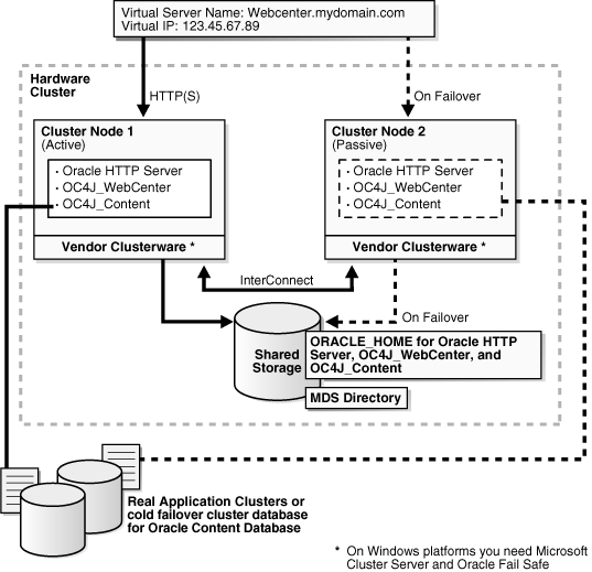
Figure 6-4 Active-Passive Topology with Components in Separate Oracle Homes
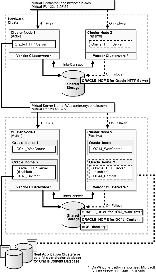
Follow the steps in Table 6-3 to create the OracleAS Cold Failover Cluster configuration. If you are installing Oracle HTTP Server and OC4J in the same Oracle home (Figure 6-3), perform the steps on the hardware cluster. If you are installing Oracle HTTP Server and OC4J in separate Oracle homes (Figure 6-4), perform each step on both hardware clusters.
Table 6-3 Overview of Installation Steps for OracleAS Cold Failover Cluster
| Step | Description | |
|---|---|---|
|
1. |
|
Preinstallation tasks, described in Section 6.3.3 include:
|
|
2. |
Install a High Availability Oracle Database |
Install a high availability database for Oracle Content DB. |
|
3. |
Set VIRTUAL_HOST_NAME Environment Variable |
Set the VIRTUAL_HOST_NAME variable to the virtual hostname. |
|
4. |
Install Oracle Application Server on the Shared Disk |
In this step, you run the installer to install Oracle Content DB, Oracle WebCenter Framework, and Oracle HTTP Server on the shared disk. |
|
5. |
(optional) Configure the Oracle Application Server Instance for SSL |
If you want the Oracle Application Server instance to use SSL, enable SSL in the Oracle Application Server installation. |
|
6. |
(optional) Create a File System on the Shared Disk for OracleAS JMS File-Based Persistence |
If you are using OracleAS JMS, create a file system on the shared disk. |
|
7. |
|
Add OPMN as a resource to the group that you created in Oracle Fail Safe. |
Before installing Oracle Application Server in an OracleAS Cold Failover Cluster, perform these procedures:
Section 6.3.3.1, "Ensure that the Event Log Service Is Running"
Section 6.3.3.3, "Verify that Microsoft Cluster Server (MSCS) Is Installed on Both Nodes"
Section 6.3.3.5, "Determine a Domain User to Administer Oracle Fail Safe"
Section 6.3.3.6, "Install Oracle Fail Safe on the Local Storage of Each Node"
The "Event Log" service must be running on both nodes in the cluster. You can check it in the Services dialog. To access the Services dialog:
Windows 2000: Select Start > Programs > Administrative Tools > Services.
Windows 2003: Select Start > Administrative Tools > Services.
You need a virtual address to associate with the cluster. A virtual address consists of a virtual hostname and an IP address. Clients access the OracleAS Cold Failover Cluster using the virtual hostname. The virtual address is in addition to each node's own hostname and IP address. Figure 6-3 shows a virtual address for the two nodes in the cluster.
To get a virtual address, consult your network administrator. Virtual hostnames and IP addresses are any valid hostname and IP address in the context of the subnet containing the cluster.
Note:
You map the virtual hostname and virtual IP address only to the active node. Do not map the virtual hostname and IP address to both active and passive nodes at the same time. When you fail over, only then map the virtual hostname and IP address to the passive node, which is now the active node.To verify that MSCS is installed on a computer, check that you can launch the Cluster Administrator from the Start menu:
Windows 2000: Select Start > Programs > Administrative Tools > Cluster Administrator.
Windows 2003: Select Start > Administrative Tools > Cluster Administrator.
Note that the "Cluster IP Address" and "Cluster Name" used by MSCS are different from the virtual hostname and virtual IP created in the previous step.
You can use the Cluster Administrator to find out the name of your cluster.
You need a domain user to own the "OracleMSCSServices" service, which gets installed when you install Oracle Fail Safe.
Requirements for this user:
This user must be defined at the domain level (as opposed to a user defined locally) because you need to specify the same user on both nodes during installation.
Make sure that you do not have a local user with the same name on either node.
This user must have Administrator privileges on both nodes in the cluster.
This user must also belong to the DBA group.
During Oracle Fail Safe installation, you specify the domain and the user using the domainname\username format. If you are running on a Microsoft Windows 2000 domain, you can also use the username@dnsDomainName format.
You need to install Oracle Fail Safe on the local storage of both nodes. For example, Figure 6-3 shows Oracle Fail Safe installed on both nodes.
Oracle Fail Safe is shipped with Oracle Application Server. It is available on the Oracle Fail Safe CD-ROM.
Overview of Steps to Install Oracle Fail Safe on Both Nodes
The sequence of steps for installing Oracle Fail Safe on each node is:
Before you start installing Oracle Fail Safe, you need to know the domain and user who will own the "OracleMSCSServices" service. This service gets installed when you install Oracle Fail Safe. See Section 6.3.3.5, "Determine a Domain User to Administer Oracle Fail Safe" for details on this user.
Install Oracle Fail Safe on node 1. See details in the next section, "Steps for Installing Oracle Fail Safe".
Restart node 1.
Install Oracle Fail Safe on node 2.
Restart node 2.
Verify the cluster using Oracle Fail Safe Manager.
Steps for Installing Oracle Fail Safe
This section describes the screens for installing Oracle Fail Safe. For a full description of the screens, refer to the Oracle Fail Safe Installation Guide.
Insert the Oracle Fail Safe CD-ROM and double-click setup.exe to start up the installer.
Welcome screen: click Next.
Specify File Locations screen:
Name: Enter the name for this Oracle home. Example: ofs.
Path (in the Destination section): Enter the full path where you want to install Oracle Fail Safe. You must install Oracle Fail Safe on the local storage. Example: C:\oracle\OFS.
Note:
You should use the same name and path for the Oracle Fail Safe installations on both nodes.Click Next.
Select Installation Type screen: Select Typical, and click Next.
This installs the following components:
Oracle Fail Safe Manager
Oracle Services for MSCS
Reboot Needed After Installation screen: This screen reminds you that you need to restart your computer after installation. Click Next.
Summary screen: Click Install.
Oracle Services for MSCS Account/Password screen:
Domain\Username: Enter the domain name and the username under which you want to run the OracleMSCSServices service.
Password and Confirm Password: Specify and confirm the password for the user.
Click OK.
Configuration Assistants screen: This screen shows the progress as the configuration assistants run.
End of Installation: Click Exit.
After installing Oracle Fail Safe, verify the cluster using Oracle Fail Safe Manager.
Start Oracle Fail Safe Manager from the Start menu:
Start > Programs > Oracle - OracleHomeName > Oracle Fail Safe Manager
OracleHomeName refers to the name that you gave to the Oracle home where you installed Oracle Fail Safe.
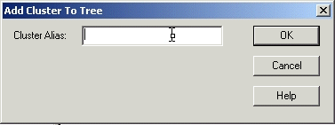
Enter the cluster name in Cluster Alias in the Add Cluster to Tree dialog (Figure 6-5). You defined the cluster name using Cluster Administrator. Click OK.
Figure 6-5 Oracle Fail Safe Manager: Add Cluster to Tree dialog
In the left frame, select the cluster. This causes Oracle Fail Safe Manager to display the Welcome dialog (Figure 6-6). In the figure, "FSWIN-CLU1" is the cluster name.
Click Verify Cluster.
You might see some warnings related to Oracle software. These warnings are expected because you have not installed any products in the cluster yet. However, if you see any system warnings, you should investigate them.
Figure 6-6 Oracle Fail Safe Manager: Welcome / Verify Cluster dialog

A group in Oracle Fail Safe is a logical collection of resources that will fail over to the standby node as a unit. Before you install Oracle Application Server in an OracleAS Cold Failover Cluster, you need to create a group using Oracle Fail Safe Manager, and add these resources to the group:
Table 6-4 Resources to Add to the Group Before Installing Oracle Application Server
| To add this resource to a group: | Use This Tool |
|---|---|
|
IP of virtual host |
Oracle Fail Safe Manager |
|
Virtual hostname |
Oracle Fail Safe Manager |
|
Shared disk |
Cluster Administrator |
Follow these steps to create and set up a group. This procedure creates a group with default attributes (for things such as failover and failback policies). You can change these attributes later if necessary. For details, see the Oracle Application Server High Availability Guide and the Oracle Fail Safe documentation.
Start up Oracle Fail Safe Manager from the Start menu:
Start > Programs > Oracle - OracleHomeName > Oracle Fail Safe Manager
OracleHomeName refers to the name that you gave to the Oracle home directory where you installed Oracle Fail Safe.
Expand the cluster on the left side.
Right-click Groups, and select Create from the pop-up menu. This starts up the Create Group wizard.
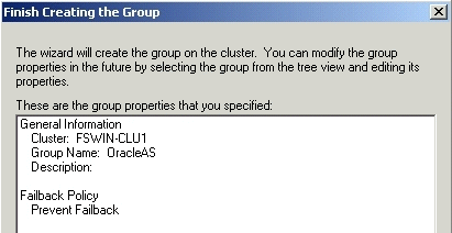
Follow the screens in the Create Group wizard to create a group called "OracleAS".
General, Step 1, screen: Enter the group name for the Oracle Application Server resources and click Next. This guide calls the group "OracleAS".
Figure 6-7 Oracle Fail Safe Manager: Create Group Wizard, General Screen

Failback Policies, Step 2, screen: Select Prevent Failback and click Next.
Figure 6-8 Oracle Fail Safe Manager: Create Group Wizard, Failback Policies Screen

Finish Creating the Group screen: Review the information and click OK.
Figure 6-9 Oracle Fail Safe Manager: Create Group Wizard, Finish Creating the Group Screen
Add Virtual Address screen: Click Yes.
Figure 6-10 Oracle Fail Safe Manager: Create Group Wizard, Add Virtual Address Screen

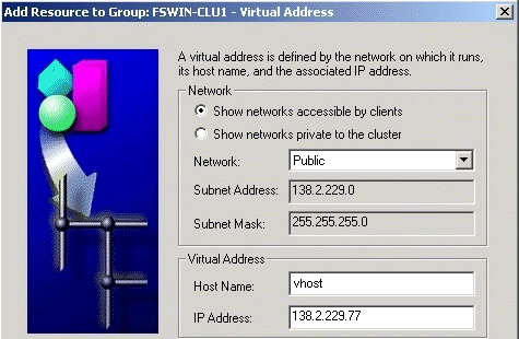
Add Resource to Group - Virtual Address screen:
Select Show networks accessible by clients.
Network: Select the name associated with the primary network interface card on the node. By default, it is "Local Area Connection".
Host Name: Enter the virtual hostname. Example: vhost.
IP Address: Enter the IP of the virtual hostname. Example: 138.2.229.77.
Click Next.
Figure 6-11 Oracle Fail Safe Manager: Create Group Wizard, Add Resource to Group - Virtual Address Screen
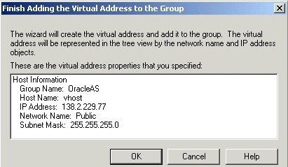
Finish Adding the Virtual Address to the Group screen: Review the information and click OK.
Figure 6-12 Oracle Fail Safe Manager: Create Group Wizard, Finish Adding the Virtual Address to the Group Screen
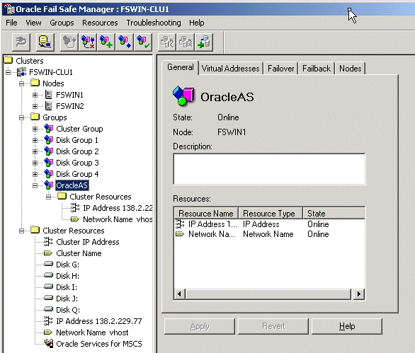
Verify that you can see the group that you just created in Oracle Fail Safe Manager (Figure 6-13) and that the group has these two resources in it:
IP address of the virtual host
Virtual hostname (shown as Network Name)
Figure 6-13 Oracle Fail Safe Manager Showing the Resources in the New Group
Using Cluster Administrator, move the shared disk where you will be installing Oracle Application Server into the group that you just created in Oracle Fail Safe Manager.
Start up Cluster Administrator from the Start menu:
Windows 2000: Start > Programs > Administrative Tools > Cluster Administrator
Windows 2003: Start > Administrative Tools > Cluster Administrator
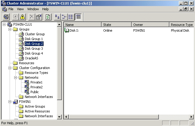
On the left side, select the disk group that contains the shared disk. In Figure 6-14, Disk I is the shared disk.
Note the "OracleAS" group on the left side. This is the group that you created in Oracle Fail Safe Manager.
Figure 6-14 Cluster Administrator Showing the Shared Disk
Drag and drop the shared disk (Disk I in the example) from the right side to the "OracleAS" group on the left side. If the Cluster Administrator prompts you to confirm (Figure 6-15), click Yes.
Figure 6-15 Cluster Administrator: Move Resources Confirmation Dialog

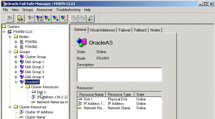
In Oracle Fail Safe Manager, check that the group now includes the shared disk.
Figure 6-16 Oracle Fail Safe Manager After Adding the Shared Disk to the Group
Set up a staticports.ini file to use when installing the middle tiers. See Section 2.5.4, "Using Custom Port Numbers (the "Static Ports" Feature)" for details on creating the staticports.ini file.
Note:
The ports must be different from those used for other Oracle homes on the same node. To check the ports assigned to components in any Oracle home, run the following commands:C:\> ORACLE_HOME/opmn/bin/opmnctl startall C:\> ORACLE_HOME/opmn/bin/opmnctl status -l
This section lists the steps for installing OracleAS Cold Failover Cluster.
If you are installing Oracle HTTP Server and OC4J in separate Oracle homes, you need to perform each of these steps on both clusters.
Step 1 Perform Preinstallation Steps
Perform the preinstallation steps listed in Section 6.3.3, "Preinstallation Steps for OracleAS Cold Failover Cluster".
Step 2 Install a High Availability Oracle Database
You need a database for Oracle Content DB. In high availability topologies, you should use high availability databases, such as cold failover cluster database or Real Application Clusters database.
See Section 2.3, "Requirements for Oracle Content Database" for more information on database requirements for Oracle Content DB.
Step 3 Set VIRTUAL_HOST_NAME Environment Variable
Set the VIRTUAL_HOST_NAME environment variable to the virtual hostname on both nodes of the hardware cluster. To find out more about how to set environment variables, see Section 2.7, "Environment Variables".
Step 4 Install Oracle Application Server on the Shared Disk
To install Oracle Application Server on the shared disk of the hardware cluster, perform the following steps:
Install Oracle Application Server on the shared disk of the hardware cluster from node 1.
For OracleAS Cold Failover Cluster with Oracle HTTP Server and WebCenter Suite in the Same Oracle Home
Perform a basic installation as described in Chapter 4, "Basic Installation".
For OracleAS Cold Failover Cluster with Components in Separate Oracle Homes
If you are installing on the hardware cluster where you want to run Oracle HTTP Server, follow the steps in Section 5.2.5, "Installing Oracle HTTP Server". During installation, perform the following actions:
On the "Specify Port Configuration Options" screen, specify the staticports.ini file you created in Section 6.3.3.8, "Set up staticports.ini File".
If you want to route all requests to OC4J through the Oracle HTTP Server, select Configure this Oracle HTTP Server instance to be part of an Oracle Application Server cluster on the "Cluster Topology Configuration" screen. Specify the IP Address and Port for the multicast address shared by all the nodes in the cluster.
If you do not want to route all requests to OC4J through the Oracle HTTP Server, deselect Configure this Oracle HTTP Server instance to be part of an Oracle Application Server cluster on the "Cluster Topology Configuration" screen.
If you are installing on the hardware cluster where you want to run Oracle WebCenter Framework and Oracle Content DB, you need to perform the following two installations:
An advanced installation of Oracle WebCenter Framework as described in Section 5.2.4, "Installing Oracle WebCenter Framework".
An advanced installation of Oracle Content DB as described in Section 5.2.3, "Installing Oracle Content Database".
During the installation of Oracle WebCenter Framework, perform the following actions:
On the "Specify Port Configuration Options" screen, specify the staticports.ini file you created in Section 6.3.3.8, "Set up staticports.ini File".
On the "Administration Settings" screen, select Start Oracle Enterprise Manager 10g ASControl in this instance if you want to configure Application Server Control for administering the OC4J instance. Otherwise, deselect this option. You should select this option in only one Oracle home in the cluster topology.
If you want to route all requests to OC4J through the Oracle HTTP Server, select Configure this instance to be part of an Oracle Application Server cluster topology on the "Cluster Topology Configuration" screen. Specify the IP Address and Port for the multicast address shared by all the nodes in the cluster. Select Access this OC4J Instance from a separate Oracle HTTP Server.
If you do not want to route all requests to OC4J through the Oracle HTTP Server, deselect Configure this instance to be part of an Oracle Application Server cluster topology on the "Cluster Topology Configuration" screen.
During the installation of Oracle Content DB, perform the following actions:
On the "Specify Port Configuration Options" screen, specify the staticports.ini file you created in Section 6.3.3.8, "Set up staticports.ini File".
On the "Administration Settings" screen, select Start Oracle Enterprise Manager 10g ASControl in this instance if you want to configure Application Server Control for administering the OC4J instance. Otherwise, deselect this option. You should select this option in only one Oracle home in the cluster topology.
If you want to route all requests to OC4J through the Oracle HTTP Server, select Configure this instance to be part of an Oracle Application Server cluster topology on the "Cluster Topology Configuration" screen. Specify the IP Address and Port for the multicast address shared by all the nodes in the cluster.
If you do not want to route all requests to OC4J through the Oracle HTTP Server, deselect Configure this instance to be part of an Oracle Application Server cluster topology on the "Cluster Topology Configuration" screen.
Configure the Windows Service for OPMN.
If you are installing OracleAS Cold Failover Cluster with Oracle HTTP Server and WebCenter Suite in the Same Oracle Home:
During a basic installation, the installer does not create the Windows Service for OPMN. You must create the Windows Service postinstallation.
To create the Windows Service for OPMN, you can use the SC tool (sc.exe), which is a services control management tool provided by Microsoft. The SC tool is included in the Windows Resource Kit.
Note:
Before you use this procedure, make sure that the version of thesc.exe program you are using is version 5.0.2134.1 or later. For more information, refer to the Microsoft Web site.Run the following command to create the service for OPMN. Note that the SC tool requires a space after each option.
sc create Oracle-<instance_name>ProcessManager
     binPath= "<oracle_home>\opmn\bin\opmn.exe -S"
If you are installing OracleAS Cold Failover Cluster with Components in Separate Oracle Homes:
Stop the Oracle Application Server Services on node 1, and set their startup type to manual.
Display the Services window.
Windows 2000: Select Start > Programs > Administrative Tools > Services.
Windows 2003: Select Start > Administrative Tools > Services.
Stop this service.
Oracle-<InstanceName>ProcessManager
To stop a service, right-click the service and select Stop from the pop-up menu.
Set the start type of the service listed above to manual.
Right-click the service, and select Properties.
Select Manual from the "Startup Type" section, and click OK.
Remove the ORACLE_HOME directory.
Fail over the Cluster group created in the preinstallation to node 2.
Use Oracle Fail Safe to move the group that you created in Oracle Fail Safe.
Start up Oracle Fail Safe Manager.
Right-click the group and select "Move to a different node".
Install Oracle HTTP Server, Oracle Content DB and/or Oracle WebCenter Framework on the shared disk of the hardware cluster from node 2 using the installation steps in step 1. Make sure that you use the same values as you did in the earlier install.
Step 5 Disable Oracle HTTP Server on Nodes with Oracle Content DB (Distributed Installations Only)
This step is required only if you performed a distributed installation in step 4.
Disable Oracle HTTP Server on the Oracle homes where you installed Oracle Content DB.
Set the status of Oracle HTTP Server to disabled in the ORACLE_HOME\opmn\conf\opmn.xml file:
<ias-component id="HTTP_Server" status="disabled">
Stop and restart all components in the Oracle home.
C:\> ORACLE_HOME\bin\opmnctl stopall
C:|> ORACLE_HOME\bin\opmnctl startall
Step 6 (optional) Configure the Oracle Application Server Instance for SSL
This step is required only if you are using SSL.
Edit the ORACLE_HOME\Apache\Apache\conf\httpd.conf file on each node as follows:
Add the following line to the httpd.conf to load the certheaders_module.
LoadModule certheaders_module modules/ApacheModuleCertHeaders.dll
Add a virtual host directive.
<VirtualHost *:7777>
ServerName myworkplace.com
Port 443
ServerAdmin you@youraddress.com
RewriteEngine On
RewriteOptions inherit
SimulateHTTPS On
</VirtualHost>
Restart Oracle HTTP Server on all the nodes.
Step 7 (optional) Create a File System on the Shared Disk for OracleAS JMS File-Based Persistence
If you are using OracleAS JMS with file-based persistence, create a file system on the shared disk for the OracleAS JMS queues. Add this shared disk to the Oracle Fail Safe group using the Cluster Administrator. You can do this by performing steps 6 and 7 in Section 6.3.3.7, "Create a Group in Oracle Fail Safe".
Step 8 Make OPMN Highly Available
Add OPMN as a resource to the group that you created in Oracle Fail Safe. See Section 6.3.5, "Postinstallation Steps: Make OPMN Highly Available" for details.
To make OPMN highly available, add it to the Oracle Fail Safe group that you created in Section 6.3.3.7, "Create a Group in Oracle Fail Safe". OPMN corresponds to the Oracle-<InstanceName>ProcessManager service.
Start up Oracle Fail Safe Manager from the Start menu.
Start > Programs > Oracle - OracleHomeName > Oracle Fail Safe Manager
OracleHomeName refers to the name that you gave to the Oracle home directory where you installed Oracle Fail Safe.
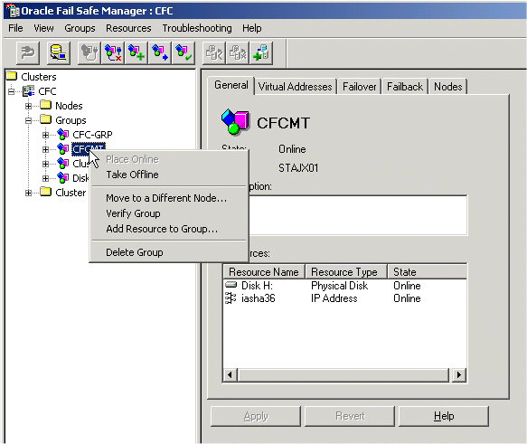
On the left side, expand Groups, right-click the group that you created in Section 6.3.3.7, "Create a Group in Oracle Fail Safe", and select Add Resource to Group. This starts up the Add Resource to Group wizard.
Figure 6-17 Oracle Fail Safe Manager: Add Resource to Group
Perform these steps in the Add Resource to Group wizard:
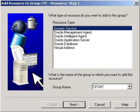
Resource, Step 1
Select Generic Service, verify that the group is correct, and click Next.
Figure 6-18 Add Resource to Group Wizard (Adding OPMN), Resource, Step 1 Screen
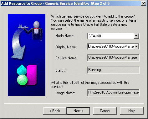
Generic Service Identity, Step 2
Select Oracle-<InstanceName>ProcessManager from Display Name, and click Next.
Figure 6-19 Add Resource to Group Wizard (Adding OPMN), Generic Service Identity, Step 2 Screen
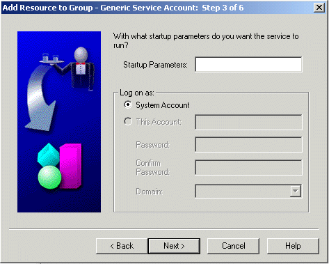
Generic Service Account, Step 3
There are no startup parameters for OPMN. Click Next.
Figure 6-20 Add Resource to Group Wizard (Adding OPMN), Generic Service Account, Step 3 Screen
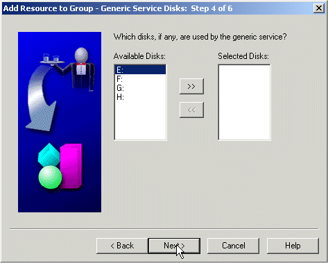
Generic Service Disks, Step 4
There should not be anything under Selected Disks. Click Next.
Figure 6-21 Add Resource to Group Wizard (Adding OPMN), Generic Service Disks, Step 4 Screen
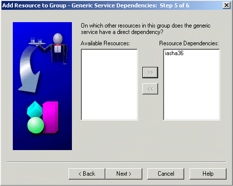
Generic Service Dependencies, Step 5
Move the Network Name to the Resource Dependencies column. Click Next.
Figure 6-22 Add Resource to Group Wizard (Adding OPMN), Generic Service Dependencies, Step 5 Screen
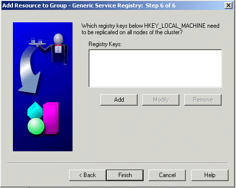
Generic Service Registry, Step 6: Click Finish.
Figure 6-23 Add Resource to Group Wizard (Adding OPMN), Generic Service Registry, Step 6 Screen
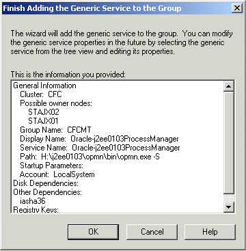
Finish Adding the Generic Service to the Group
Verify the information and click OK. In particular, check that both nodes in the cluster are listed under Possible Owner Nodes.
Figure 6-24 Add Resource to Group Wizard (Adding OPMN), Finish Adding the Generic Service to the Group Screen
Confirm Add Generic Service to Group screen: Click Yes.
Figure 6-25 Add Resource to Group Wizard (Adding OPMN), Confirm Add Generic Service to Group Screen

Oracle Fail Safe Manager now configures the Process Manager service so that both nodes in the cluster can run it. When it is done, it displays a screen similar to Figure 6-26. Click OK in the success dialog.
Figure 6-26 Add Resource to Group Wizard (Adding OPMN), Final Screen
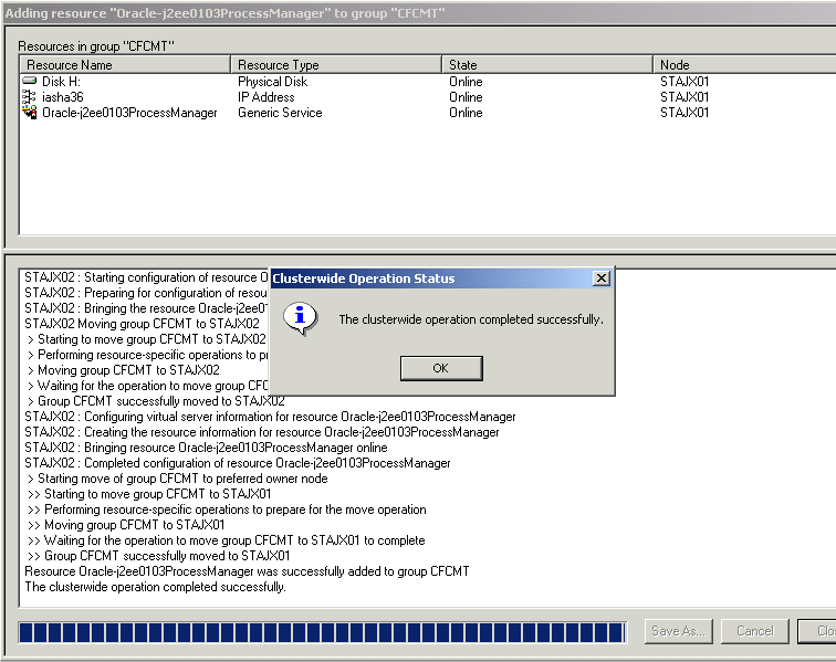
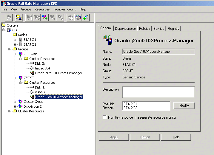
In the Oracle Fail Safe Manager, you should see the Process Manager service listed under the group.
Figure 6-27 Oracle Fail Safe Manager With the Process Manager Service Added to the Group
This section describes how to install Oracle Application Server in OracleAS Disaster Recovery configurations. OracleAS Disaster Recovery is one of the high availability environments supported by Oracle Application Server.
Contents of this section:
Section 6.4.2, "Setting up the OracleAS Disaster Recovery Environment"
Section 6.4.3, "Installing Oracle Application Server in an OracleAS Disaster Recovery Environment"
Section 6.4.5, "Upgrading OracleAS Guard Release 10.1.2.n.n with Release 10.1.3.2.0"
Use the OracleAS Disaster Recovery environment when you want to have two physically separate sites in your environment. One site is the production site, and the other site is the standby site. The production site is active, while the standby site is passive; the standby site becomes active when the production site goes down.
OracleAS Disaster Recovery supports a number of basic topologies for the configuration of the Infrastructure and middle tier on production and standby sites. OracleAS Disaster Recovery supports these basic topologies:
Symmetrical topologies -- strict mirror of the production site with collocated Oracle Identity Management and OracleAS Metadata Repository Infrastructure
Asymmetrical topologies -- simple asymmetric standby topology with collocated Oracle Identity Management and OracleAS Metadata Repository Infrastructure
Separate OracleAS Metadata Repository for OracleAS Portal with collocated Oracle Identity Management and OracleAS Metadata Repository Infrastructure (the Departmental Topology)
Distributed Application OracleAS metadata Repositories with Non collocated Oracle Identity Management and OracleAS Metadata Repository Infrastructure
Redundant Multiple OracleAS 10.1.3.2.0 Home J2EE Topology
Redundant Single OracleAS 10.1.3.2.0 Home J2EE Topology Integrated with an Existing Oracle Identity Management 10.1.2.0.2 Topology
In a symmetric topology, each node in the standby site corresponds to a node in the production site. This includes the nodes running both OracleAS Infrastructure and middle tiers. In an asymmetric topology, the number of instances required on the standby site are fewer than the number on the production site and the number of instances required on the standby site must be the minimum set of instances required to run your site in the event of a switchover or failover operation. The last two supported topologies are particularly important in OracleAS Release 10.1.3.2.0. See the Oracle Application Server High Availability Guide for a detailed description of these topologies.
As a small variation to this environment, you can set up the OracleAS Infrastructure on the production site in an OracleAS Cold Failover Cluster environment. See Section 6.4.2.4, "If You Want to Use OracleAS Cold Failover Cluster on the Production Site (OracleAS 10.1.2.n.n only)" for details.
For these supported topologies, OracleAS Guard will be installed in every Oracle home on every system that is part of your production and standby topology configured for the OracleAS Disaster Recovery solution.
OracleAS Guard can be installed as a standalone install kit located on OracleAS Companion CD #2. See Section 6.4.4, "Installing the OracleAS 10g (10.1.3.2.0) Standalone Install of OracleAS Guard into Oracle Homes" for more information about when this standalone kit should be installed.
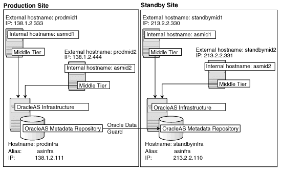
Figure 6-28 shows an example symmetric OracleAS Disaster Recovery environment. Each site has two nodes running middle tiers and a node running OracleAS Infrastructure.
For OracleAS Disaster Recovery to work, data between the production and standby sites must be synchronized so that failover can happen very quickly. Configuration changes done at the production site must be synchronized with the standby site.
You need to synchronize two types of data. The synchronization method depends on the type of data:
Use Oracle Data Guard to synchronize data in the OracleAS Metadata Repository databases on the production and standby sites. You can configure Oracle Data Guard to perform the synchronization.
Use the backup and recovery scripts to synchronize data outside of the database (such as data stored in configuration files).
See the Oracle Application Server High Availability Guide for details on how to use Oracle Data Guard and the backup and recovery scripts.
Figure 6-28 OracleAS Disaster Recovery Environment
Before you can install Oracle Application Server in an OracleAS Disaster Recovery environment, you have to perform these steps:
Section 6.4.2.1, "Ensure Nodes Are Identical at the Operating System Level"
Section 6.4.2.3, "Set Up Identical Hostnames on Both Production and Standby Sites"
Ensure that the nodes are identical with respect to the following items:
The nodes are running the same version of the operating system.
The nodes have the same operating system patches and packages.
You can install Oracle Application Server in the same directory path on all nodes.
The same component must use the same port number on the production and standby sites. For example, if Oracle HTTP Server is using port 80 on the production site, it must also use port 80 on the standby site. To ensure this is the case, create a staticports.ini file for use during installation. This file enables you to specify port numbers for each component. See Section 2.5.4, "Using Custom Port Numbers (the "Static Ports" Feature)" for details.
The names of the corresponding nodes on the production and standby sites must be identical, so that when you synchronize data between the sites, you do not have to edit the data to fix the hostnames.
For the Infrastructure Nodes
For the node running the infrastructure, set up a virtual name. To do this, specify an alias for the node in the C:\Windows\system32\drivers\etc\hosts file.
For example, on the infrastructure node on the production site, the following line in the hosts file sets the alias to asinfra:
138.1.2.111 prodinfra asinfra
On the standby site, the following line sets the node's alias to asinfra.
213.2.2.110 standbyinfra asinfra
When you install OracleAS Infrastructure on the production and standby sites, you specify this alias (asinfra) in the Specify Virtual Hostname screen. The configuration data will then contain this alias for the infrastructure nodes.
For the Middle-Tier Nodes
For the nodes running the middle tiers, you cannot set up aliases like you did for the infrastructure nodes because the installer does not display the Specify Virtual Hostname screen for middle-tier installations. When installing middle tiers, the installer determines the hostname automatically by calling the gethostname() function. You want to be sure that for each middle-tier node on the production site, the corresponding node on the standby site returns the same hostname.
Note:
For 10.1.3.x midtier installations onwards, you may also set the VIRTUAL_HOST_NAME environment variable appropriately before the installation for installer to pick up the virtual name correctly for the install. Hostnames may be allowed to be the same or different across primary and standby in this case.To do this, set up a local, or internal, hostname, which could be different from the public, or external, hostname. You can change the names of the nodes on the standby site to match the names of the corresponding nodes on the production site, or you can change the names of the nodes on both production and standby sites to be the same. This depends on other applications that you might be running on the nodes, and whether changing the node name will affect those applications.
On the nodes whose local names you want to change, set the _CLUSTER_NETWORK_NAME_ environment variable to specify the new local fully qualified name (for example, asmid1.oracle.com).
Note:
You must set the_CLUSTER_NETWORK_NAME_ environment variable as a "user" environment variable, not as a "system" environment variable.Enable the other nodes in the OracleAS Disaster Recovery environment to be able to resolve the node using the new local hostname. You can do this in one of two ways:
Method 1: Edit the C:\Windows\system32\drivers\etc\hostsfile on each node on both sites. This method does not involve configuring DNS servers, but you have to maintain the hosts file on each node in the OracleAS Disaster Recovery environment. For example, if an IP address changes, you have to update the files on all the nodes, and restart the nodes.
Method 1 Details
On each node on the production site, include these lines in the C:\Windows\system32\drivers\etc\hosts file. The IP addresses resolve to nodes on the production site.
Note:
In thehosts file, be sure that the line that identifies the current node comes immediately after the localhost definition (the line with the 127.0.0.1 address).127.0.0.1 localhost 138.1.2.333 asmid1.oracle.com asmid1 138.1.2.444 asmid2.oracle.com asmid2 138.1.2.111 asinfra.oracle.com asinfra
On each node on the standby site, include these lines in the hosts file. The IP addresses resolve to nodes on the standby site.
Note:
In thehosts file, be sure that the line that identifies the current node comes immediately after the localhost definition (the line with the 127.0.0.1 address).127.0.0.1 localhost 213.2.2.330 asmid1.oracle.com asmid1 213.2.2.331 asmid2.oracle.com asmid2 213.2.2.110 asinfra.oracle.com asinfra
Set the order of hostname resolution so that the node resolves hostnames by reading the hosts file first. If the hosts file does not contain an entry for the desired hostname, then the node will resolve the hostname through DNS.
You can do this by adding the entries to the hosts file, then running the "nbtstat -R" command to purge cached information and reload the name table. See your system administrator for details.
Method 2: Set up separate internal DNS servers for the production and standby sites. This configuration allows nodes on each site (production or standby) to resolve hostnames within the site. Above the internal DNS servers are the corporate, or external, DNS servers. The internal DNS servers forward non-authoritative requests to the external DNS servers. The external DNS servers do not know about the existence of the internal DNS servers. See Figure 6-29.
Method 2 Details
Make sure the external DNS names are defined in the external DNS zone. Example:
prodmid1.us.oracle.com     IN  A  138.1.2.333
prodmid2.us.oracle.com     IN  A  138.1.2.444
prodinf.us.oracle.com      IN  A  138.1.2.111
standbymid1.us.oracle.com  IN  A  213.2.2.330
standbymid2.us.oracle.com  IN  A  213.2.2.331
standbyinf.us.oracle.com   IN  A  213.2.2.110
At the production site, create a new zone at the production site using a domain name different from your external domain name. To do this, populate the zone data files with entries for each node in the OracleAS Disaster Recovery environment.
For the infrastructure node, use the virtual name or alias.
For the middle-tier nodes, use the node name (the value in the _CLUSTER_NETWORK_NAME_ environment variable).
The following example uses "asha" as the domain name for the new zone.
asmid1.asha    IN  A  138.1.2.333
asmid2.asha    IN  A  138.1.2.444
asinfra.asha   IN  A  138.1.2.111
Do the same for the standby site. Use the same domain name that you used for the production site.
asmid1.asha    IN  A  213.2.2.330
asmid1.asha    IN  A  213.2.2.331
asinfra.asha   IN  A  213.2.2.110
For each node on the production site, configure the DNS resolver to point to the internal DNS servers instead of the external DNS server.
Table 6-5 Configure the DNS Resolver to Point to Internal DNS Servers
| Windows 2000 or Windows 2003 |
|---|
|
Do the same for the nodes on the standby site, but use the IP address of the internal DNS server for the standby site.
Create a separate entry for Oracle Data Guard in the internal DNS servers. This entry is used by Oracle Data Guard to ship redo data to the database on the standby site.
In the next example, the "remote_infra" entry points to the infrastructure node on the standby site. This name is used by the TNS entries on both the production and standby sites so that if a switchover occurs, the entry does not have to be changed.
Figure 6-30 Entry for Oracle Data Guard in the Internal DNS Servers

On the production site, the DNS entries look like this:
asmid1.asha        IN  A  138.1.2.333
asmid2.asha        IN  A  138.1.2.444
asinfra.asha       IN  A  138.1.2.111
remote_infra.asha  IN  A  213.2.2.110
On the standby site, the DNS entries look like this:
asmid1.asha        IN  A  213.2.2.330
asmid2.asha        IN  A  213.2.2.331
asinfra.asha       IN  A  213.2.2.110
remote_infra.asha  IN  A  138.1.2.111
Verifying that the Nodes Resolve the Hostnames Correctly
After making the changes and restarting the nodes, check that the nodes resolve the hostnames properly by running the following commands:
On the middle-tier nodes on both sites, run the hostname command. This should return the internal hostname. For example, the command should return "asmid1" if you run it on prodmid1 and standbymid1.
C:\> hostname
asmid1
On each node, ping the other nodes in the environment using the internal hostname as well as the external hostname. The command should be successful. For example, from the first midtier node, prodmid1, run the following commands:
C:> ping prodinfra        ping the production infrastructure node
Pinging prodinfra [138.1.2.111] with 32 bytes of data:
Reply from 138.1.2.111: bytes=32 time<1ms TTL=128

C:> ping asinfra          ping the production infrastructure node
Pinging prodinfra [138.1.2.111] with 32 bytes of data:
Reply from 138.1.2.111: bytes=32 time<1ms TTL=128

C:> ping asmid2           ping the second production midtier node
Pinging asmid2 [138.1.2.444] with 32 bytes of data:
Reply from 138.1.2.444: bytes=32 time<1ms TTL=128

C:> ping prodmid2         ping the second production midtier node
Pinging asmid2 [138.1.2.444] with 32 bytes of data:
Reply from 138.1.2.444: bytes=32 time<1ms TTL=128

C:> ping standbymid1       ping the first standby midtier node
Pinging asmid2 [213.2.2.330] with 32 bytes of data:
Reply from 213.2.2.330: bytes=32 time<1ms TTL=128
Note:
You must perform this installation in an OracleAS Release 10.1.2.n.n environment, where n.n represents 0.0 or higher. This information is presented here for informative purposes only.On the production site of a OracleAS Disaster Recovery system, you can set up the OracleAS Infrastructure to run in a OracleAS Cold Failover Cluster configuration. In this case, you have two nodes in a hardware cluster, and you install the OracleAS Infrastructure on a shared disk. See Chapter 11, "Installing in High Availability Environments: OracleAS Cold Failover Cluster" in the Oracle Application Server Installation Guide 10g Release 2 (10.1.2) Documentation set for details.
Figure 6-31 Infrastructure in an OracleAS Cold Failover Cluster Configuration
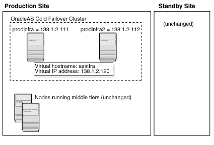
To set up OracleAS Cold Failover Cluster in this environment, use the virtual IP address (instead of the physical IP address) for asinfra.asha on the production site. The following example assumes 138.1.2.120 is the virtual IP address.
asmid1.asha          IN  A  138.1.2.333
asmid2.asha          IN  A  138.1.2.444
asinfra.asha         IN  A  138.1.2.120         this is a virtual IP address
remote_infra.asha    IN  A  213.2.2.110
On the standby site, you still use the physical IP address for asinfra.asha, but the remote_infra.asha uses the virtual IP address.
asmid1.asha          IN  A  213.2.2.330
asmid2.asha          IN  A  213.2.2.331
asinfra.asha         IN  A  213.2.2.110         physical IP address
remote_infra.asha    IN  A  138.1.2.120         virtual IP address
Need to Create the Password File in Oracle Fail Safe
When you are setting up OracleAS Cold Failover Cluster in an OracleAS Disaster Recovery environment, you need to create the password file when you are adding the OracleAS Metadata Repository to the Oracle Fail Safe group; that is, add a Resource Type of Oracle Database.
See Section 11.12.2, "Make OracleAS Metadata Repository Highly Available" in the Oracle Application Server Installation Guide 10g Release 2 (10.1.2) Documentation set.
In step 3c, select Yes, create the password file.
In User Name, enter SYS.
In Password and Confirm Password, enter and confirm the password that you want to set for the SYS user.
For OracleAS Release 10.1.3.2.0, you can only install middle tiers on the production and standby sites.
Install Oracle Application Server as follows:
Note:
For all of the installations, be sure to use staticports.ini to specify port numbers for the components. See Section 6.4.2.2, "Set Up staticports.ini File".Install Middle Tiers (OracleAS Release 10.1.3.2.0 only)
Install middle tiers on the production site.
Install middle tiers on the standby site.
Install OracleAS Infrastructure and Middle Tiers (Release 10.1.2.n.n only)
Note:
You must perform this installation in an OracleAS Release 10.1.2.n.n environment, where n.n represents 0.0 or higher. This information is presented here for informative purposes only.Install OracleAS Infrastructure on the production site.
Install OracleAS Infrastructure on the standby site.
Start the OracleAS Infrastructure in each site before installing the middle tiers for that site.
Install middle tiers on the production site.
Install middle tiers on the standby site.
Note:
You must perform this installation in an OracleAS Release 10.1.2.n.n environment, where n.n represents 0.0 or higher. This information is presented here for informative purposes only.In an OracleAS Release 10.1.2.0.0 environment, you must install the Oracle Identity Management and the OracleAS Metadata Repository components of OracleAS Infrastructure on the same node. You cannot distribute the components over multiple nodes. In an OracleAS Release 10.1.2.0.2 environment, you can distribute the components over multiple nodes.
The installation steps are similar to that for OracleAS Cold Failover Cluster. See Section 11.3, "Installing an OracleAS Cold Failover Cluster (Infrastructure) Configuration" in the Oracle Application Server Installation Guide 10g Release 2 (10.1.2) Documentation set for the screen sequence.
Note the following points:
Select Configuration Options screen: be sure you select High Availability and Replication. See Table 11–7, step 2.
In the Specify Virtual Hostname screen, enter the fully qualified local hostname as the virtual address (for example, asinfra.oracle.com). See Table 11–7, step 6.
Depending on your configuration, you can install OracleAS 10.1.3.2.0 middle tiers or OracleAS 10.1.2.n.n middle tiers, where n.n represents 0.0 or higher.
OracleAS Release 10.1.3.2.0
On OracleAS release 10.1.3.2.0, you can install any type of middle tier that you like:
For installing Oracle WebCenter Framework with Oracle HTTP Server, see Section 5.2.2, "Installing Oracle WebCenter Framework with Oracle HTTP Server".
For installing Oracle WebCenter Framework, see Section 5.2.4, "Installing Oracle WebCenter Framework".
For installing Oracle HTTP Server, see Section 5.2.5, "Installing Oracle HTTP Server".
OracleAS Release 10.1.2.n.n
Note:
You must perform this installation in an OracleAS Release 10.1.2.n.n environment, where n.n represents 0.0 or higher. This information is presented here for informative purposes only.On OracleAS Release 10.1.2.n.n, you can install any type of middle tier that you like:
For installing J2EE and Web Cache, see Section 7.9 "Installing J2EE and Web Cache in a Database-Based Farm Repository and with Oracle Identity Management Access" in the Oracle Application Server Installation Guide for 10g Release 2 (10.1.2).
For installing Portal and Wireless or Business Intelligence and Forms, see Section 7.13, "Installing Portal and Wireless or Business Intelligence and Forms".
Note the following points on OracleAS 10.1.2.n.n:
When the installer prompts you to register with Oracle Internet Directory, and asks you for the Oracle Internet Directory hostname, enter the alias of the node running OracleAS Infrastructure (for example, asinfra.oracle.com).
OracleAS 10g (10.1.3.2.0) standalone install of OracleAS Guard is located on Companion CD Disk 2. This standalone install of OracleAS Guard can be installed in the following environments:
In its own home in the case when you are cloning an instance or topology to a new standby system (see the section on standby site cloning in Oracle Application Server High Availability Guide for more information).
Oracle database server home for an OracleAS Metadata Repository configuration created using OracleAS Metadata Repository Creation Assistant.
OracleAS Disaster Recovery full site upgrade from OracleAS 10g (9.0.4) to OracleAS 10g (10.1.3.2.0) (see the chapter on OracleAS Disaster Recovery site upgrade procedure in Oracle Application Server High Availability Guide for more information).
OracleAS Guard patch upgrade from OracleAS 10g (10.1.3.0) to OracleAS 10g (10.1.3.2) (see Section 6.4.5, "Upgrading OracleAS Guard Release 10.1.2.n.n with Release 10.1.3.2.0" for more information).
If this is an upgrade installation of OracleAS Guard, make a copy of your dsa.conf configuration file to save your current settings for your OracleAS Guard environment. After running the OracleAS 10g (10.1.3.2.0) standalone install kit of OracleAS Guard, you can restore your saved dsa.conf configuration file with your settings to continue using the same settings for the upgraded OracleAS Guard environment.
To run the OracleAS 10g (10.1.3.2.0) standalone install kit of OracleAS Guard, run the kit in the following directory path:
On Windows systems:
Disk2\asg\Disk1\install\setup.exe
Choose the type of install that you want. Choose Typical for most installations. Choose Custom or Reinstall for upgrading from an older release of OracleAS Guard to the current release.
Enter the oc4jadmin account password to continue the installation.
If you already have an OracleAS Disaster Recovery environment set up using OracleAS Guard Release 10.1.2.n.n (where n.n represents 0.0 or higher, you can upgrade OracleAS Guard in your environment to take advantage of new features and support for the topologies described in Section 6.4.1, "OracleAS Disaster Recovery: Introduction". To upgrade your OracleAS Disaster Recovery environment, follow these basic steps:
Stop the OracleAS Guard server in all OracleAS 10.1.2.n.n Oracle homes on both production and standby sites using the following opmnctl command:
On Windows systems:
<ORACLE_HOME>\opmn\bin\opmnctl stopall
Install the OracleAS 10g (10.1.3.2.0) standalone install of OracleAS Guard into each Oracle home on the production and standby sites.
If multiple Oracle homes exist on the same system, ensure that different ports are configured for each of the OracleAS Guard servers in this configuration file.
Because this is an upgrade installation of OracleAS Guard, make a copy of your dsa.conf configuration file to save your current settings for your OracleAS Guard environment. After running the OracleAS 10g (10.1.3.2.0) standalone install kit of OracleAS Guard, you can restore your saved dsa.conf configuration file with your settings to continue using the same settings for the upgraded OracleAS Guard environment.
On Windows systems:
<ORACLE_HOME>\dsa\dsa.conf
Start the OracleAS Guard server in all OracleAS 10.1.3.2.0 Oracle homes on both production and standby sites using the following opmnctl command:
On Windows systems:
<ORACLE_HOME>\opmn\bin\opmnctl startall
<ORACLE_HOME>\opmn\bin\opmnctl startproc ias-component=ASG
For information on how to manage your OracleAS Disaster Recovery environment, such as setting up Oracle Data Guard and configuring the OracleAS Metadata Repository database, see the Oracle Application Server High Availability Guide.