


|
This following sections describe alternative architectures for a WebLogic Server cluster:
This section defines terms used in this document.
In this context the architecture refers to how the tiers of an application are deployed to one or more clusters.
A Web application is divided into several “tiers” that correspond to the logical services the application provides. Because not all Web applications are alike, your application may not utilize all of the tiers described below. Also keep in mind that the tiers represent logical divisions of an application’s services, and not necessarily physical divisions between hardware or software components. In some cases, a single machine running a single WebLogic Server instance can provide all of the tiers described below.
The web tier provides static content (for example, simple HTML pages) to clients of a Web application. The web tier is generally the first point of contact between external clients and the Web application. A simple Web application may have a web tier that consists of one or more machines running WebLogic Express, Apache, Netscape Enterprise Server, or Microsoft Internet Information Server.
The presentation tier provides dynamic content (for example, servlets or Java Server Pages) to clients of a Web application. A cluster of WebLogic Server instances that hosts servlets and/or JSPs comprises the presentation tier of a web application. If the cluster also serves static HTML pages for your application, it encompasses both the web tier and the presentation tier.
The object tier provides Java objects (for example, Enterprise JavaBeans or RMI classes) and their associated business logic to a Web application. A WebLogic Server cluster that hosts EJBs provides an object tier.
A cluster architecture in which all tiers of the Web application are deployed to a single WebLogic Server cluster is called a combined tier architecture.
The De-Militarized Zone (DMZ) is a logical collection of hardware and services that is made available to outside, untrusted sources. In most Web applications, a bank of Web servers resides in the DMZ to allow browser-based clients access to static HTML content.
The DMZ may provide security against outside attacks to hardware and software. However, because the DMZ is available to untrusted sources, it is less secure than an internal system. For example, internal systems may be protected by a firewall that denies all outside access. The DMZ may be protected by a firewall that hides access to individual machines, applications, or port numbers, but it still permits access to those services from untrusted clients.
In this document, the term load balancer describes any technology that distributes client connection requests to one or more distinct IP addresses. For example, a simple Web application may use the DNS round-robin algorithm as a load balancer. Larger applications generally use hardware-based load balancing solutions such as those from Alteon WebSystems, which may also provide firewall-like security capabilities.
Load balancers provide the capability to associate a client connection with a particular server in the cluster, which is required when using in-memory replication for client session information. With certain load balancing products, you must configure the cookie persistence mechanism to avoid overwriting the WebLogic Server cookie which tracks primary and secondary servers used for in-memory replication. See For a discussion of external load balancers, session cookie persistence, and the WebLogic Server session cookie, see “Load Balancing HTTP Sessions with an External Load Balancer” on page 5-2 for more information.
A proxy plug-in is a WebLogic Server extension to an HTTP server—such as Apache, Netscape Enterprise Server, or Microsoft Internet Information Server—that accesses clustered servlets provided by a WebLogic Server cluster. The proxy plug-in contains the load balancing logic for accessing servlets and JSPs in a WebLogic Server cluster. Proxy plug-ins also contain the logic for accessing the replica of a client’s session state if the primary WebLogic Server hosting the session state fails.
The recommended basic architecture is a combined tier architecture—all tiers of the Web application are deployed to the same WebLogic Server cluster. This architecture is illustrated in the following figure.
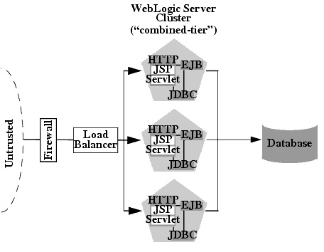
The benefits of the Recommended Basic Architecture are:
Because a single cluster hosts static HTTP pages, servlets, and EJBs, you can configure the entire Web application and deploy/undeploy objects using the WebLogic Server Console. You do not need to maintain a separate bank of Web servers (and configure WebLogic Server proxy plug-ins) to benefit from clustered servlets.
Using load balancing hardware directly in front of the WebLogic Server cluster enables you to use advanced load balancing policies for accessing both HTML and servlet content. For example, you can configure your load balancer to detect current server loads and direct client requests appropriately.
Placing a firewall in front of your load balancing hardware enables you to set up a De-Militarized Zone (DMZ) for your web application using minimal firewall policies.
The combined tier architecture offers the best performance for applications in which most or all of the servlets or JSPs in the presentation tier typically access objects in the object tier, such as EJBs or JDBC objects
| Note: | When using a third-party load balancer with in-memory session replication, you must ensure that the load balancer maintains a client’s connection to the WebLogic Server instance that hosts its primary session state (the point-of-contact server). For more information about load balancers, see For a discussion of external load balancers, session cookie persistence, and the WebLogic Server session cookie, see “Load Balancing HTTP Sessions with an External Load Balancer” on page 5-2. |
While a combined tier architecture, such as the Recommended Basic Architecture, meets the needs of many Web applications, it limits your ability to fully employ the load balancing and failover capabilities of a cluster. Load balancing and failover can be introduced only at the interfaces between Web application tiers, so, when tiers are deployed to a single cluster, you can only load balance between clients and the cluster.
Because most load balancing and failover occurs between clients and the cluster itself, a combined tier architecture meets the needs of most Web applications.
However, combined-tier clusters provide no opportunity for load balancing method calls to clustered EJBs. Because clustered objects are deployed on all WebLogic Server instances in the cluster, each object instance is available locally to each server. WebLogic Server optimizes method calls to clustered EJBs by always selecting the local object instance, rather than distributing requests to remote objects and incurring additional network overhead.
This collocation strategy is, in most cases, more efficient than load balancing each method request to a different server. However, if the processing load to individual servers becomes unbalanced, it may eventually become more efficient to submit method calls to remote objects rather than process methods locally.
To utilize load balancing for method calls to clustered EJBs, you must split the presentation and object tiers of the Web application onto separate physical clusters, as described in the following section.
Consider the frequency of invocations of the object tier by the presentation tier when deciding between a combined tier and multi-tier architecture. If presentation objects usually invoke the object tier, a combined tier architecture may offer better performance than a multi-tier architecture.
This section describes the Recommended Multi-Tier Architecture, in which different tiers of your application are deployed to different clusters.
The recommended multi-tier architecture uses two separate WebLogic Server clusters: one to serve static HTTP content and clustered servlets, and one to serve clustered EJBs. The multi-tier cluster is recommended for Web applications that:
| Note: | Consider the frequency of invocations from the presentation tier to the object tier when considering a multi-tier architecture. If presentation objects usually invoke the object tier, a combined tier architecture may offer better performance than a multi-tier architecture. |
The following figure depicts the recommended multi-tier architecture.

In the Recommended Multi-Tier Architecture the application tiers are hosted on two separate physical layers of hardware and software.
The web/presentation layer consists of a cluster of WebLogic Server instances dedicated to hosting static HTTP pages, servlets, and JSPs. This servlet cluster does not host clustered objects. Instead, servlets in the presentation tier cluster act as clients for clustered objects, which reside on an separate WebLogic Server cluster in the object layer.
The object layer consists of a cluster of WebLogic Server instances that hosts only clustered objects—EJBs and RMI objects as necessary for the web application. By hosting the object tier on a dedicated cluster, you lose the default collocation optimization for accessing clustered objects described in Optimization for Collocated Objects. However, you gain the ability to load balance on each method call to certain clustered objects, as described in the following section.
The multi-tier architecture provides these advantages:
By hosting servlets and EJBs on separate clusters, servlet method calls to EJBs can be load balanced across multiple servers. This process is described in detail in Load Balancing Clustered Objects in a in Multi-Tier Architecture.
Separating the presentation and object tiers onto separate clusters provides more options for distributing the load of the web application. For example, if the application accesses HTTP and servlet content more often than EJB content, you can use a large number of WebLogic Server instances in the presentation tier cluster to concentrate access to a smaller number of servers hosting EJBs.
By utilizing additional WebLogic Server instances, the multi-tier architecture has fewer points of failure than the basic cluster architecture. For example, if a WebLogic Server that hosts EJBs fails, the HTTP- and servlet-hosting capacity of the Web application is not affected.
By separating the presentation and object tiers onto separate clusters, you can use a firewall policy that places only the servlet/JSP cluster in the DMZ. Servers hosting clustered objects can be further protected by denying direct access from untrusted clients. For more information, see Security Options for Cluster Architectures.
WebLogic Server’s collocation optimization for clustered objects, described in Optimization for Collocated Objects, relies on having a clustered object (the EJB or RMI class) hosted on the same server instance as the replica-aware stub that calls the object.
The net effect of isolating the object tier is that no client (HTTP client, Java client, or servlet) ever acquires a replica-aware stub on the same server that hosts the clustered object. Because of this, WebLogic Server cannot use its collocation optimization (described in Optimization for Collocated Objects), and servlet calls to clustered objects are automatically load balanced according to the logic contained in the replica-aware stub. The following figure depicts a client accessing a clustered EJB instance in the multi-tier architecture.
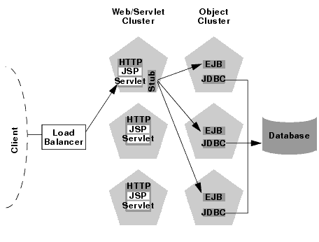
Tracing the path of the client connection, you can see the implication of isolating the object tier onto separate hardware and software:
The servlet looks up the EJB on the WebLogic Server cluster that hosts clustered objects. The servlet obtains a replica-aware stub for the bean, which lists the addresses of all servers that host the bean, as well as the load balancing logic for accessing bean replicas.
| Note: | EJB replica-aware stubs and EJB home load algorithms are specified using elements of the EJB deployment descriptor. See “weblogic-ejb-jar.xml Deployment Descriptor Reference” in Programming WebLogic Enterprise JavaBeans for more information. |
In this example, if the same WebLogic Server cluster hosted both servlets and EJBs (as in the Recommended Basic Architecture), WebLogic Server would not load balance requests for the EJB. Instead, the servlet would always invoke methods on the EJB replica hosted on the local server. Using the local EJB instance is more efficient than making remote method calls to an EJB on another server. However, the multi-tier architecture enables remote EJB access for applications that require load balancing for EJB method calls.
Because the multi-tier architecture provides load balancing for clustered object calls, the system generally utilizes more IP sockets than a combined-tier architecture. In particular, during peak socket usage, each WebLogic Server in the cluster that hosts servlets and JSPs may potentially use a maximum of:
For example, in Figure 9-2, each server in the servlet/JSP cluster could potentially open a maximum of five sockets. This maximum represents a worst-case scenario where primary and secondary session states are equally dispersed throughout the servlet cluster, and each server in the servlet cluster simultaneously accesses a remote object on each server in the object cluster. In most cases, the number of sockets actual sockets in use would be less than this maximum.
If you use a pure-Java sockets implementation with the multi-tier architecture, ensure that you configure enough socket reader threads to accommodate the maximum potential socket usage. For details, see Configuring Reader Threads for Java Socket Implementation.
Because the multi-tier architecture uses a hardware load balancer, you must configure the load balancer to maintain a “sticky” connection to the client’s point-of-contact server if you use in-memory session state replication. For details, see Configure Load Balancing Method for EJBs and RMIs .
This section summarizes the limitations of multi-tier cluster architectures.
Because the Recommended Multi-Tier Architecture cannot optimize object calls using the collocation strategy, the Web application incurs network overhead for all method calls to clustered objects. This overhead may be acceptable, however, if your Web application requires any of the benefits described in Benefits of Multi-Tier Architecture.
For example, if your Web clients make heavy use of servlets and JSPs but access a relatively small set of clustered objects, the multi-tier architecture enables you to concentrate the load of servlets and object appropriately. You may configure a servlet cluster of ten WebLogic Server instances and an object cluster of three WebLogic Server instances, while still fully utilizing each server’s processing power.
If you place a firewall between the servlet cluster and object cluster in a multi-tier architecture, you must bind all servers in the object cluster to public DNS names, rather than IP addresses. Binding those servers with IP addresses can cause address translation problems and prevent the servlet cluster from accessing individual server instances.
If the internal and external DNS names of a WebLogic Server instance are not identical, use the ExternalDNSName attribute for the server instance to define the server's external DNS name. Outside the firewall the ExternalDNSName should translate to external IP address of the server.
Use of ExternalDNSName is required for configurations in which a firewall is performing Network Address Translation, unless clients are accessing WebLogic Server using t3 and the default channel. For instance, ExternalDNSName is required for configurations in which a firewall is performing Network Address Translation, and clients are accessing WebLogic Server using HTTP via a proxy plug-in.
You can configure WebLogic Server clusters to operate alongside existing Web servers. In such an architecture, a bank of Web servers provides static HTTP content for the Web application, using a WebLogic proxy plug-in or HttpClusterServlet to direct servlet and JSP requests to a cluster.
The following sections describe two alternative proxy architectures.
The two-tier proxy architecture illustrated in the following figure is similar to the Recommended Basic Architecture, except that static HTTP servers are hosted on a bank of Web servers.
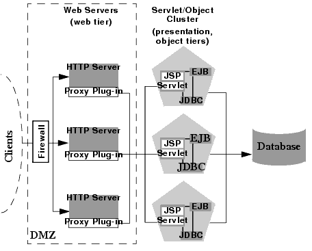
The two-tier proxy architecture contains two physical layers of hardware and software.
The proxy architecture utilizes a layer of hardware and software dedicated to the task of providing the application’s web tier. This physical web layer can consist of one or more identically-configured machines that host one of the following application combinations:
HttpClusterServlet
Regardless of which Web server software you select, keep in mind that the physical tier of Web servers should provide only static Web pages. Dynamic content—servlets and JSPs—are proxied via the proxy plug-in or HttpClusterServlet to a WebLogic Server cluster that hosts servlets and JSPs for the presentation tier.
The recommended two-tier proxy architecture hosts the presentation and object tiers on a cluster of WebLogic Server instances. This cluster can be deployed either on a single machine or on multiple separate machines.
The Servlet/Object layer differs from the combined-tier cluster described in Recommended Basic Architecture in that it does not provide static HTTP content to application clients.
You can also use a bank of Web servers as the front-end to a pair of WebLogic Server clusters that host the presentation and object tiers. This architecture is shown in the following figure.
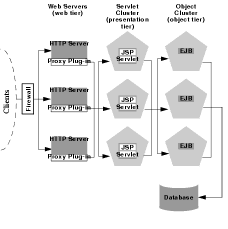
This architecture provides the same benefits (and the same limitations) as the Recommended Multi-Tier Architecture. It differs only insofar as the web tier is placed on a separate bank of Web servers that utilize WebLogic proxy plug-ins.
Using standalone Web servers and proxy plug-ins provides the following advantages:
If you already have a Web application architecture that provides static HTTP content to clients, you can easily integrate existing Web servers with one or more WebLogic Server clusters to provide dynamic HTTP and clustered objects.
Using a Web server proxy at the front-end of your Web application enables you to use familiar firewall policies to define your DMZ. In general, you can continue placing the Web servers in your DMZ while disallowing direct connections to the remaining WebLogic Server clusters in the architecture. The figures above depict this DMZ policy.
Using standalone Web servers and proxy plug-ins limits your Web application in the following ways:
The Web servers in the proxy architecture must be configured using third-party utilities, and do not appear within the WebLogic Server administrative domain. You must also install and configure WebLogic proxy plug-ins to the Web servers in order to benefit from clustered servlet access and failover.
When you use proxy plug-ins or the HttpClusterServlet to access clustered servlets, the load balancing algorithm is limited to a simple round-robin strategy.
Using a load balancer directly with a WebLogic Server cluster provides several benefits over proxying servlet requests. First, using WebLogic Server with a load balancer requires no additional administration for client setup—you do not need to set up and maintain a separate layer of HTTP servers, and you do not need to install and configure one or more proxy plug-ins. Removing the Web proxy layer also reduces the number of network connections required to access the cluster.
Using load balancing hardware provides more flexibility for defining load balancing algorithms that suit the capabilities of your system. You can use any load balancing strategy (for example, load-based policies) that your load balancing hardware supports. With proxy plug-ins or the HttpClusterServlet, you are limited to a simple round-robin algorithm for clustered servlet requests.
Note, however, that using a third-party load balancer may require additional configuration if you use in-memory session state replication. In this case, you must ensure that the load balancer maintains a “sticky” connection between the client and its point-of-contact server, so that the client accesses the primary session state information. When using proxy plug-ins, no special configuration is necessary because the proxy automatically maintains a sticky connection.
The boundaries between physical hardware/software layers in the recommended configurations provide potential points for defining your Web application’s De-Militarized Zone (DMZ). However, not all boundaries can support a physical firewall, and certain boundaries can support only a subset of typical firewall policies.
The sections that follow describe several common ways of defining your DMZ to create varying levels of application security.
The basic firewall configuration uses a single firewall between untrusted clients and the Web server layer, and it can be used with either the Recommended Basic Architecture or Recommended Multi-Tier Architecture cluster architectures.
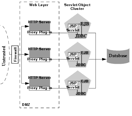
In the above configuration, the single firewall can use any combination of policies (application-level restrictions, NAT, IP masquerading) to filter access to three HTTP servers. The most important role for the firewall is to deny direct access to any other servers in the system. In other words, the servlet layer, the object layer, and the database itself must not be accessible from untrusted clients.
Note that you can place the physical firewall either in front of or behind the Web servers in the DMZ. Placing the firewall in front of the Web servers simplifies your firewall policies, because you need only permit access to the web servers and deny access to all other systems.
If you place a firewall between the proxy layer and the cluster, follow these configuration guidelines:
ExternalDNSName attribute for the server instance to define the its external DNS name. Outside the firewall the ExternalDNSName should translate to external IP address of the server instance. | Note: | If the clustered servers segregate https and http traffic on a pair of custom channels, see “Channels, Clusters, and Firewalls” in Designing and Configuring WebLogic Server Environments. |
By denying access to all but the Web server layer, the basic firewall configuration creates a small-footprint DMZ that includes only three Web servers. However, a more conservative DMZ definition might take into account the possibility that a malicious client may gain access to servers hosting the presentation and object tiers.
For example, assume that a hacker gains access to one of the machines hosting a Web server. Depending on the level of access, the hacker may then be able to gain information about the proxied servers that the Web server accesses for dynamic content.
If you choose to define your DMZ more conservatively, you can place additional firewalls using the information in Additional Security for Shared Databases.
If you use load balancing hardware with a recommended cluster architecture, you must decide how to deploy the hardware in relationship to the basic firewall. Although many hardware solutions provide security features in addition to load balancing services, most sites rely on a firewall as the first line of defense for their Web applications. In general, firewalls provide the most well-tested and familiar security solution for restricting web traffic, and should be used in front of load balancing hardware, as shown below.
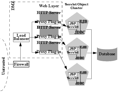
The above setup places the load balancer within the DMZ along with the web tier. Using a firewall in this configuration can simplify security policy administration, because the firewall need only limit access to the load balancer. This setup can also simplify administration for sites that support internal clients to the Web application, as described below.
If you support internal clients that require direct access to your Web application (for example, remote machines that run proprietary Java applications), you can expand the basic firewall configuration to allow restricted access to the presentation tier. The way in which you expand access to the application depends on whether you treat the remote clients as trusted or untrusted connections.
If you use a Virtual Private Network (VPN) to support remote clients, the clients may be treated as trusted connections and can connect directly to the presentation tier going through a firewall. This configuration is shown below.

If you do not use a VPN, all connections to the Web application (even those from remote sites using proprietary client applications) should be treated as untrusted connections. In this case, you can modify the firewall policy to permit application-level connections to WebLogic Server instances hosting the presentation tier, as shown in the following figure.
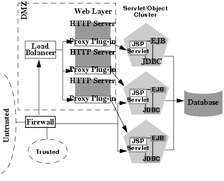
If you use a single database that supports both internal data and data for externally-available Web applications, you should consider placing a hard boundary between the object layer that accesses your database. Doing so simply reinforces the DMZ boundaries described in Basic Firewall for Proxy Architectures by adding an additional firewall.
The following configuration places an additional firewall in front of a database server that is shared by the Web application and internal (trusted) clients. This configuration provides additional security in the unlikely event that the first firewall is breached, and a hacker ultimately gains access to servers hosting the object tier. Note that this circumstance should be extremely unlikely in a production environment—your site should have the capability to detect and stop a malicious break-in long before a hacker gains access to machines in the object layer.
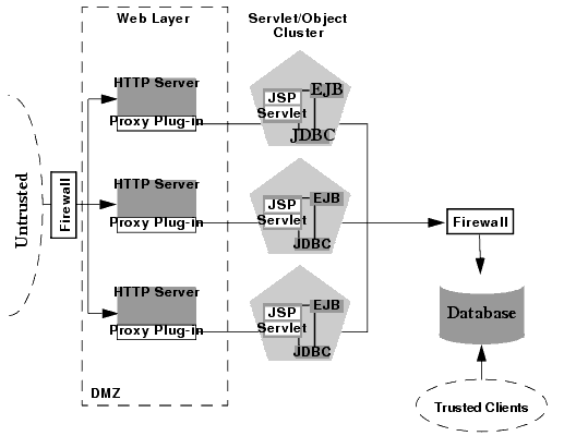
In the above configuration, the boundary between the object tier and the database is hardened using an additional firewall. The firewall maintains a strict application-level policy that denies access to all connections except JDBC connections from WebLogic Servers hosting the object tier.


|