| Oracle® Retail Warehouse Management System UI User Guide Release 14.1 E58327-01 |
|


 Previous |
 Next |
| Oracle® Retail Warehouse Management System UI User Guide Release 14.1 E58327-01 |
|
Previous |
Next |
The support function modules assist system administrators and users with high privilege levels in maintaining specifications for every integral part of the distribution center.
The modules found under the support functions umbrella are:
The Activity Setup module is used to configure existing activities and to define indirect activities.
The Administration Setup module is used to configure system level functions, such as facilities, menus, print queues, system parameters, translations, user messages, users, and working days.
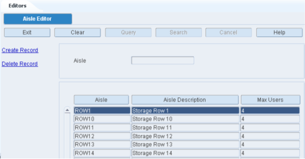
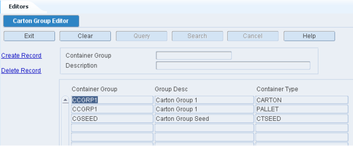
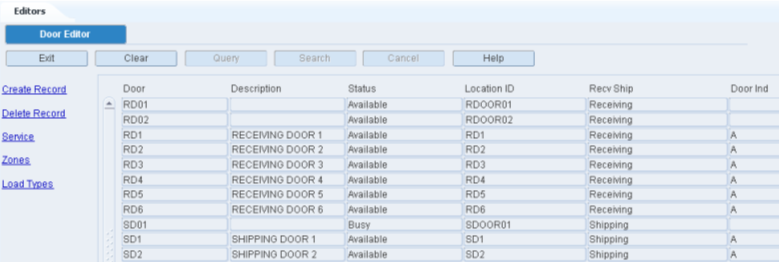
The DC Setup module is used to further define process areas within the DC. This includes defining aisles, regions, doors, putaway plans, put to store location relationships, and carton groups.
The Equipment/Zone Setup module is used to set up equipment classes, equipment, zones, and zone groups.
The Item Setup module is used to further define item warehouse characteristics to optimize distribution processing. It is also used to associate items to specific activities and locations within the DC.
The Labor Management Module is used to define all of the components required to establish a Labor Standard. These components include labor elements, labor factors, labor conditions, labor PFD allowances, etc.
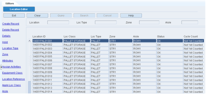
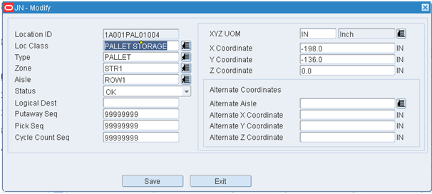
The Location Setup module is used to define location types, locations, and reference points in the DC so inventory can be tracked and processed effectively.
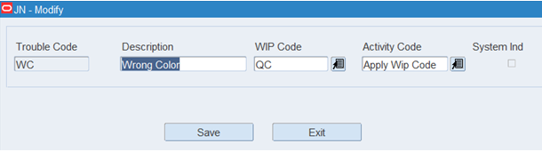
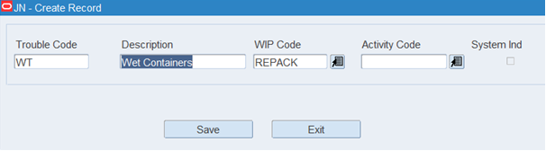
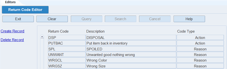
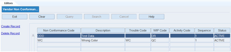
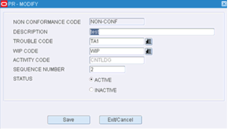
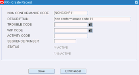
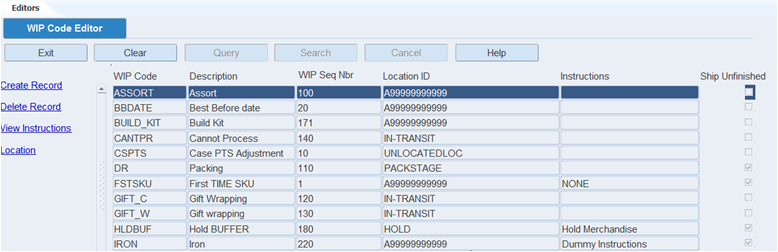
The Processing /Returns module is used to define WIP codes, attributes, and returns that enable value added processes.
The Transportation Setup module is used to shipping destinations, carriers, trailers, routes, route days, route destinations, and carrier service routes.
The User Setup module is used to define users in the system, associate users to activity groups, and to associate users to equipment.
The Activity Setup module is used to configure existing activities and to define indirect activities. This section includes the following topics:
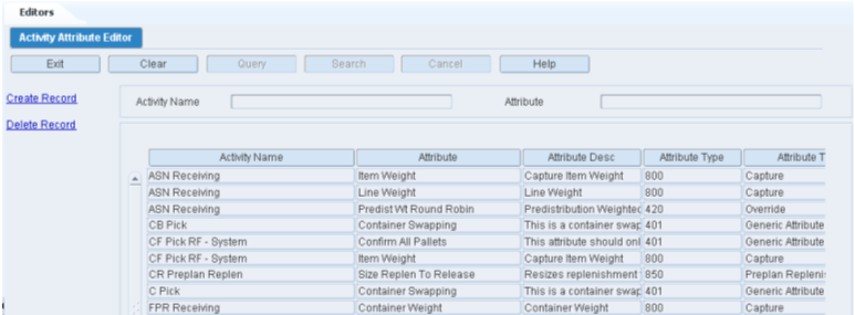
The Activity Attribute Editor allows you to associate and view the attributes assigned to each activity.
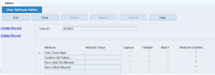
To maintain activity attributes, navigate to Setup - Activity -> Activity Attribute Editor. The Activity Attribute Editor window opens.
Display All Activity Attributes
Click the Search button.
Display a Subset of Activity Attributes
If any activity attributes are currently displayed, click the Clear button.
Click the Query button.
To search for a single activity attribute, enter specific attribute in the Attribute query field, or click the LOV button and select the attribute. To search for activity attributes by activity, enter the name of the activity in the Activity Name query field, or click the LOV button and select the activity.
Click the Search button. The activity attributes that match the search criterion are displayed.
Edit an Activity Attribute
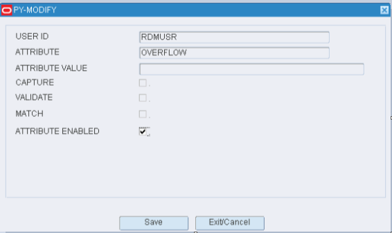
On the Activity Attribute Editor window, double-click the activity attribute that you want to edit. The Modify window opens.
Select or clear the Attribute Enabled check box as necessary.
Click Save to save any changes and close the Modify window.
Assign an Attribute to an Activity
On the Activity Attribute Editor window, click Create Record. The Create Record window opens.
In the Attribute Name field, enter the name of the activity or click the LOV button and select the activity.
In the Attribute field, enter the ID of the attribute you want to associate with the current activity, or click the LOV button and select the attribute.
To make the activity attribute available to users, select the Attribute Enabled check box.
Click Save to save the changes and close the Create Record window.
Delete an Activity Attribute
On the Activity Attribute Editor window, select the attribute that you want to delete.
Click Delete Record.
When prompted to delete the record, click Yes.
Exit the Activity Attribute Editor Window
Click the Exit button to close the window.
The Activity Editor contains all of the core activities that are supported by RWMS. An activity is defined as any task that requires both physical and logical action. It allows the user to see if the activity is task management enabled, and if yes, set the priority of the task and the priority threshold. It also allows you to turn on Labor Management for supported Activities as long as the System Parameter Enable Labor Management is set to Y.
Activities are classified as:
Basic Activity: A basic activity is an activity that can only be performed one way with no variations.
Basic Extended Activity: Basic extended activities are those activities where the system provides variations on how to perform the activity such as radio frequency versus paper, system generated label versus generic labels, and so on.
All Radio Frequency screens in the application and a limited number of GUI screens are defined as unique activities. The following is the limited list of GUI Screens defined as activities:
Apply WIP Code
Confirm Paper Pick to Belt
Confirm Paper Pick to Pallet
Confirm Paper Unit Pick
Container Checking
Electronic Return Processing
Inventory Edit by Container
Order Consolidation
Packing
Paper Return Processing
Quality Assurance
Resolve Trouble
Ticketing
The Activity Editor window is used to capture and store all data interactions for the activities listed in this editor. For example, when a Bulk Pick is performed, the following details are captured: Entry into screen, Location ID, Container ID, Quantity, Done key and Exit key.
To maintain activities, navigate to Setup - Activity -> Activity Editor. The Activity Editor window opens.
Display All Activities
Click the Search button.
Display an Activity
If any Activity Codes are currently displayed, click the Clear button.
Click the Query button.
To search for an Activity Code, enter the activity code in the Activity Code query field, or click the LOV button and select the activity code.
Click the Search button. The basic activities along with the extended activities and user activities that match the search criterion are displayed.
|
Note: To view the user activities associated to the selected basic activity, click the User Activities radio button. |
Edit an Activity
On the Activity Editor window, double-click the activity code that you want to edit. The Modify window opens.
The following fields are pre-populated and you cannot edit them:
Activity Code: is the name of the system supported activity.
Description: is the long description for the activity.
Basic Activity Code: the only time this will not match the activity code field is when you copy an existing activity and create a user defined activity. The new activity code performs the exact same functions as the original activity code.
Functional Area: identifies the type of process (receiving, transport, picking, replenishment, cycle count, shipping) where the activity is actually performed.
Copy Allowed: this flag is enabled when the user is allowed to copy an existing activity to create a new user activity.
Task Creation: this flag indicates that this activity appears on the Task Command Queue.
Task Dispatch: this flag indicates that the task appears in the RF Task Administration screen and allow for interleaving with the use of an activity group.
Labor Mgmt Available: this flag indicates if Labor Management is supported within the application for this activity. If checked this activity can calculate Labor Standards. (This flag is not editable by the user).
Default Labor Code: this is the Labor Code currently marked as default from the Labor Template Editor. (This code is displayed only and is not editable).
Presentation Type: this indicates how the activity can be performed (RF, GUI, Paper).
Transaction Timing: this indicates when the activity is generated (real time or post).
On Hold: this flag indicates whether a replenishment activity can be placed on hold until the location reaches it reorder point. This field is checked if the On Hold functionality is supported for the specific activity and blank if not supported.
Labor Management Enabled checkbox allows you to enable this specific activity for Labor Standards creation. This field can only be updated when Labor Management Available is checked.
Max Inactive Time is the amount of time a user can go inactive on the RF session before the system will ask ”What is your current location”. This is used by Labor Management for travel calculations. This field can only be updated when Labor Management Available is checked.
Check the On Demand checkbox to print labels on demand instead of printing them all at once. This option allows you to request a specific number of labels from a printer on the warehouse floor. This flag is disabled for unsupported activities and enabled for supported activities. The default setting for enabled activities is blank meaning do not print on demand.
The Label Configuration field is populated from the Label Configuration Editor and the valid values are PRINT_WITH_WAVE and PRINT_ON_DEMAND.
The Screen Name field displays the technical screen name and cannot be edited.
Set the Default Priority. This is the numeric priority (ranging from 1 to 99) assigned by the user to an activity when the activity is first created. This field is enabled for all activities supported by task management and disabled for all other activities.
|
Note: An activity with Default Priority set to 1 is more important than an activity with Default Priority set to 99. |
Set the Priority Threshold. This is the numeric priority where proximity (distance) takes precedence over priority. For example, if the priority threshold is set to 4, any activity with a priority 1 to a priority 4 is done in priority order. That is, all priority 1 activities done first, followed by all priority 2 activities, followed by all 3 activities and priority 4 activities. At the point where the system starts performing activities with priority 5 or above the system looks for the activities that are closest to the current location of the user.
Check the Assign Equipment Flag as necessary. This flag is checked when the activity requires equipment (forklift, turret truck, cherry picker, etc) to perform the activity.
Click Save to save the changes and close the Modify window.
RWMS, when installed has rules for specific activities that can be defined (turned on). A rule is defined as a condition that triggers an action when it occurs. You can define the conditions that make the rule true and the resulting priority change.
The Activity Priority Rules Editor is used to assign rules to supported task management activities. The rules determine when a task's default priority should be raised.
You assign an operator (<, >, =) to each rule. This is used to compare the rule to a value you define. If the rule is met, the priority of the task changes by a factor you decide on.
On the Activity Editor window, select an activity, click Define Rules. The Activity Priority Rules Editor window opens.
Validate that correct activity code has been selected by viewing the top block.
In the Rule Name field, select the rule using the LOV.
In the Operator field, select an operator for the rule (=, <, >). For rules that do not require an operator this field is disabled.
In the Value field, enter the value that triggers the rule.
In the UOM (Unit of Measure) field click the LOV button and select the desired UOM for this rule.
In the Priority Change field, enter the number to raise the priority of the task if the rule is met. The lower the number the higher the priority. Based on the rule selection, the priority change is either absolute or incremental.
Absolute means the priority changes from its current default priority to the new priority.
Incremental means the priority changes from its current default priority and gets reduced by the incremental number. For example, if default priority is 10 and incremental change is 3, the new priority is 7.
Click Add. The rule moves to the Assigned Rules table.
Click Save to save the change and close the Activity Priority Rules Editor window.
Delete a Defined Rule
On the Activity Editor, place the cursor on the desired activity and click Define Rules to open the Activity Priority Rules Editor.
On the Activity Priority Rules Editor, place a check mark next to the rule you want to delete (disable).
Click Remove. The rule is removed from the Assigned Rules table.
Click Save to save the rules and close the window.
Table 4-1 Supported Rules
| Activity Code | Rule Name | Description |
|---|---|---|
|
BD_REPLEN |
FPL_QTY_VS_ROP_2 |
Unit Qty vs. Re-Order Qty as a percentage. Calculation: (Unit Qty / Re-order Qty)*100 |
|
BD_REPLEN |
FPL_QTY_IS_ZERO_WITH_DIST_QTY |
FPL is Empty with pending Distributed Qty, Calculation: Unit Qty = 0, Demand Qty>0 |
|
BD_REPLEN |
FPL_QTY_VS_ROP_1 |
FPL Unit Qty vs. Re-Order Qty as a percentage. Calculation: (Unit Qty / Re-order Qty)*100 |
|
BD_REPLEN |
FPL_QTY_VS_CAPACITY_2 |
FPL Unit Qty vs. Capacity as a percentage. Calculation: (Unit Qty / Capacity)*100 |
|
BD_REPLEN |
FPL_QTY_IS_ZERO |
FPL is Empty. Calculation: Unit Qty = 0 |
|
BD_REPLEN |
FPL_QTY_REACH_ROP |
FPL Qty is less than or equal to Re-order Point Qty |
|
BD_REPLEN |
FPL_QTY_LESS_DIST_QTY |
FPL Unit Qty is less than Distributed Qty. Calculation: Demand Qty > Unit Qty |
|
BD_REPLEN |
TASK_AGE |
Elevate the priority of aging tasks after a specified time interval incrementally |
|
BD_REPLEN |
FPL_QTY_VS_CAPACITY_1 |
FPL Unit Qty vs. Capacity as a percentage. Calculation: (Unit Qty / Capacity)*100 |
|
BP_REPLEN |
TASK_AGE |
Elevate the priority of aging tasks after a specified time interval incrementally |
|
BR_REPLEN |
TASK_AGE |
Elevate the priority of aging tasks after a specified time interval incrementally |
|
BR_REPLEN |
FPL_QTY_VS_ROP_1 |
FPL Unit Qty vs. Re-Order Qty as a percentage. Calculation: (Unit Qty / Re-order Qty)*100 |
|
BR_REPLEN |
FPL_QTY_VS_CAPACITY_2 |
FPL Unit Qty vs. Capacity as a percentage. Calculation: (Unit Qty / Capacity)*100 |
|
BR_REPLEN |
FPL_QTY_VS_CAPACITY_1 |
FPL Unit Qty vs. Capacity as a percentage. Calculation: (Unit Qty / Capacity)*100 |
|
BR_REPLEN |
FPL_QTY_REACH_ROP |
FPL Qty is less than or equal to Re-Order Point Qty |
|
BR_REPLEN |
FPL_QTY_LESS_DIST_QTY |
FPL Unit Qty is less than Distributed Qty. Calculation: Demand Qty > Unit Qty |
|
BR_REPLEN |
FPL_QTY_IS_ZERO |
FPL is Empty. Calculation: Unit Qty = 0 |
|
BR_REPLEN |
FPL_QTY_VS_ROP_2 |
FPL Unit Qty vs. Re-Order Qty as a percentage. Calculation: (Unit Qty / Re-order Qty)*100 |
|
BR_REPLEN |
FPL_QTY_IS_ZERO_WITH_DIST_QTY |
FPL is Empty with pending Distributed Qty. Calculation: Unit Qty = 0, Demand Qty>0 |
|
BT_REPLEN |
FPL_QTY_LESS_DIST_QTY |
FPL Unit Qty is less than Distributed Qty. Calculation: Demand Qty > Unit Qty |
|
BT_REPLEN |
FPL_QTY_IS_ZERO_WITH_DIST_QTY |
FPL is Empty with pending Distributed Qty. Calculation: Unit Qty = 0, Demand Qty>0 |
|
BT_REPLEN |
FPL_QTY_VS_CAPACITY_2 |
FPL Unit Qty vs. Capacity as a percentage. Calculation: (Unit Qty / Capacity)*100 |
|
BT_REPLEN |
FPL_QTY_VS_ROP_1 |
FPL Unit Qty vs. Re-Order Qty as a percentage. Calculation: (Unit Qty / Re-order Qty)*100 |
|
BT_REPLEN |
FPL_QTY_VS_CAPACITY_1 |
FPL Unit Qty vs. Capacity as a percentage. Calculation: (Unit Qty / Capacity)*100 |
|
BT_REPLEN |
TASK_AGE |
Elevate the priority of aging tasks after a specified time interval incrementally |
|
BT_REPLEN |
FPL_QTY_IS_ZERO |
FPL is Empty. Calculation: Unit Qty = 0 |
|
BT_REPLEN |
FPL_QTY_REACH_ROP |
FPL Qty is less than or equal to Re-Order Point Qty |
|
BT_REPLEN |
FPL_QTY_VS_ROP_2 |
FPL Unit Qty vs. Re-Order Qty as a percentage. Calculation: (Unit Qty / Re-order Qty)*100 |
|
B_PICK |
TRAILER_OPENED |
Opened Trailer |
|
B_PICK |
TASK_AGE |
Elevate the priority of aging tasks after a specified time interval incrementally |
|
B_PICK |
ORDER_SHIP_DATE |
Ship Date for an order is within the specified time range |
|
B_PICK |
ORDER_IN_STORE_DATE |
In Store Date for an order is within the specified time range |
|
CD_REPLEN |
FPL_QTY_IS_ZERO_WITH_DIST_QTY |
FPL is Empty with pending Distributed Qty. Calculation: Unit Qty = 0, Demand Qty>0 |
|
CD_REPLEN |
FPL_QTY_LESS_DIST_QTY |
FPL Unit Qty is less than Distributed Qty. Calculation: Demand Qty > Unit Qty |
|
CD_REPLEN |
FPL_QTY_VS_ROP_1 |
FPL Unit Qty vs. Re-Order Qty as a percentage. Calculation: (Unit Qty / Re-order Qty)*100 |
|
CD_REPLEN |
FPL_QTY_VS_ROP_2 |
FPL Unit Qty vs. Re-Order Qty as a percentage. Calculation: (Unit Qty / Re-order Qty)*100 |
|
CD_REPLEN |
FPL_QTY_IS_ZERO |
FPL is Empty. Calculation: Unit Qty = 0 |
|
CD_REPLEN |
TASK_AGE |
Elevate the priority of aging tasks after a specified time interval incrementally |
|
CD_REPLEN |
FPL_QTY_REACH_ROP |
FPL Qty is less than or equal to Re-Order Point Qty |
|
CD_REPLEN |
FPL_QTY_VS_CAPACITY_1 |
FPL Unit Qty vs. Capacity as a percentage. Calculation: (Unit Qty / Capacity)*100 |
|
CD_REPLEN |
FPL_QTY_VS_CAPACITY_2 |
FPL Unit Qty vs. Capacity as a percentage. Calculation: (Unit Qty / Capacity)*100 |
|
CE_REPLEN |
FPL_QTY_LESS_DIST_QTY |
FPL Unit Qty is less than Distributed Qty. Calculation: Demand Qty > Unit Qty |
|
CE_REPLEN |
FPL_QTY_REACH_ROP |
FPL Qty is less than or equal to Re-Order Point Qty |
|
CE_REPLEN |
FPL_QTY_VS_CAPACITY_1 |
FPL Unit Qty vs. Capacity as a percentage. Calculation: (Unit Qty / Capacity)*100 |
|
CE_REPLEN |
FPL_QTY_VS_CAPACITY_2 |
FPL Unit Qty vs. Capacity as a percentage. Calculation: (Unit Qty / Capacity)*100 |
|
CE_REPLEN |
FPL_QTY_VS_ROP_1 |
FPL Unit Qty vs. Re-Order Qty as a percentage. Calculation: (Unit Qty / Re-order Qty)*100 |
|
CE_REPLEN |
FPL_QTY_VS_ROP_2 |
FPL Unit Qty vs. Re-Order Qty as a percentage. Calculation: (Unit Qty / Re-order Qty)*100 |
|
CE_REPLEN |
FPL_QTY_IS_ZERO_WITH_DIST_QTY |
FPL is Empty with pending Distributed Qty. Calculation: Unit Qty = 0, Demand Qty>0 |
|
CE_REPLEN |
FPL_QTY_IS_ZERO |
FPL is Empty. Calculation: Unit Qty = 0 |
|
CE_REPLEN |
TASK_AGE |
Elevate the priority of aging tasks after a specified time interval incrementally |
|
CF_PICK |
TASK_AGE |
Elevate the priority of aging tasks after a specified time interval incrementally |
|
CF_PICK |
ORDER_SHIP_DATE |
Ship Date for an order is within the specified time range |
|
CF_PICK |
ORDER_IN_STORE_DATE |
In Store Date for an order is within the specified time range |
|
CF_PICK |
TRAILER_OPENED |
Opened Trailer |
|
CO_REPLEN |
TASK_AGE |
Elevate the priority of aging tasks after a specified time interval incrementally |
|
CO_REPLEN |
FPL_QTY_VS_ROP_2 |
FPL Unit Qty vs. Re-Order Qty as a percentage. Calculation: (Unit Qty / Re-order Qty)*100 |
|
CO_REPLEN |
FPL_QTY_VS_CAPACITY_2 |
FPL Unit Qty vs. Capacity as a percentage. Calculation: (Unit Qty / Capacity)*100 |
|
CO_REPLEN |
FPL_QTY_VS_CAPACITY_1 |
FPL Unit Qty vs. Capacity as a percentage. Calculation: (Unit Qty / Capacity)*100 |
|
CO_REPLEN |
FPL_QTY_REACH_ROP |
FPL Qty is less than or equal to Re-Order Point Qty |
|
CO_REPLEN |
FPL_QTY_LESS_DIST_QTY |
FPL Unit Qty is less than Distributed Qty. Calculation: Demand Qty > Unit Qty |
|
CO_REPLEN |
FPL_QTY_IS_ZERO |
FPL is Empty. Calculation: Unit Qty = 0 |
|
CO_REPLEN |
FPL_QTY_VS_ROP_1 |
FPL Unit Qty vs. Re-Order Qty as a percentage. Calculation: (Unit Qty / Re-order Qty)*100 |
|
CO_REPLEN |
FPL_QTY_IS_ZERO_WITH_DIST_QTY |
FPL is Empty with pending Distributed Qty. Calculation: Unit Qty = 0, Demand Qty>0 |
|
CP_REPLEN |
TASK_AGE |
Elevate the priority of aging tasks after a specified time interval incrementally |
|
CR_REPLEN |
FPL_QTY_IS_ZERO |
FPL is Empty. Calculation: Unit Qty = 0 |
|
CR_REPLEN |
FPL_QTY_VS_CAPACITY_2 |
FPL Unit Qty vs. Capacity as a percentage. Calculation: (Unit Qty / Capacity)*100 |
|
CR_REPLEN |
FPL_QTY_VS_ROP_1 |
FPL Unit Qty vs. Re-Order Qty as a percentage. Calculation: (Unit Qty / Re-order Qty)*100 |
|
CR_REPLEN |
FPL_QTY_VS_ROP_2 |
FPL Unit Qty vs. Re-Order Qty as a percentage. Calculation: (Unit Qty / Re-order Qty)*100 |
|
CR_REPLEN |
TASK_AGE |
Elevate the priority of aging tasks after a specified time interval incrementally |
|
CR_REPLEN |
FPL_QTY_REACH_ROP |
FPL Qty is less than or equal to Re-Order Point Qty |
|
CR_REPLEN |
FPL_QTY_VS_CAPACITY_1 |
FPL Unit Qty vs. Capacity as a percentage. Calculation: (Unit Qty / Capacity)*100 |
|
CR_REPLEN |
FPL_QTY_LESS_DIST_QTY |
FPL Unit Qty is less than Distributed Qty. Calculation: Demand Qty > Unit Qty |
|
CR_REPLEN |
FPL_QTY_IS_ZERO_WITH_DIST_QTY |
FPL is Empty with pending Distributed Qty. Calculation: Unit Qty = 0, Demand Qty>0 |
|
CS_REPLEN |
TASK_AGE |
Elevate the priority of aging tasks after a specified time interval incrementally |
|
CT_REPLEN |
FPL_QTY_VS_CAPACITY_2 |
FPL Unit Qty vs. Capacity as a percentage. Calculation: (Unit Qty / Capacity)*100 |
|
CT_REPLEN |
FPL_QTY_VS_ROP_1 |
FPL Unit Qty vs. Re-Order Qty as a percentage. Calculation: (Unit Qty / Re-order Qty)*100 |
|
CT_REPLEN |
FPL_QTY_VS_ROP_2 |
FPL Unit Qty vs. Re-Order Qty as a percentage. Calculation: (Unit Qty / Re-order Qty)*100 |
|
CT_REPLEN |
FPL_QTY_IS_ZERO |
FPL is Empty. Calculation: Unit Qty = 0 |
|
CT_REPLEN |
FPL_QTY_IS_ZERO_WITH_DIST_QTY |
FPL is Empty with pending Distributed Qty. Calculation: Unit Qty = 0, Demand Qty>0 |
|
CT_REPLEN |
FPL_QTY_REACH_ROP |
FPL Qty is less than or equal to Re-Order Point Qty |
|
CT_REPLEN |
FPL_QTY_LESS_DIST_QTY |
FPL Unit Qty is less than Distributed Qty. Calculation: Demand Qty > Unit Qty |
|
CT_REPLEN |
FPL_QTY_VS_CAPACITY_1 |
FPL Unit Qty vs. Capacity as a percentage. Calculation: (Unit Qty / Capacity)*100 |
|
CT_REPLEN |
TASK_AGE |
Elevate the priority of aging tasks after a specified time interval incrementally |
|
CYCLE_COUNT |
CYCLE_COUNT_MM_AUDIT |
Location Manually Marked for a Cycle Count - with an Audit |
|
CYCLE_COUNT |
CYCLE_COUNT_MM_NO_AUDIT |
Location Manually Marked for a Cycle Count - without an Audit |
|
CYCLE_COUNT |
TASK_AGE |
Elevate the priority of aging tasks after a specified time interval incrementally |
|
CYCLE_COUNT |
CYCLE_COUNT_SS |
Location selected by the System for a Cycle Count |
|
C_PICK |
TASK_AGE |
Elevate the priority of aging tasks after a specified time interval incrementally |
|
C_PICK |
ORDER_SHIP_DATE |
Ship Date for an order is within the specified time range |
|
C_PICK |
ORDER_IN_STORE_DATE |
In Store Date for an order is within the specified time range |
|
C_PICK |
TRAILER_OPENED |
Opened Trailer |
|
LOAD_CONTAINER |
ORDER_IN_STORE_DATE |
In Store Date for an order is within the specified time range |
|
LOAD_CONTAINER |
ORDER_SHIP_DATE |
Ship Date for an order is within the specified time range |
|
LOAD_CONTAINER |
TASK_AGE |
Elevate the priority of aging tasks after a specified time interval incrementally |
|
LOAD_CONTAINER |
TRAILER_OPENED |
Opened Trailer |
|
PL_REPLEN |
FPL_QTY_VS_CAPACITY_1 |
FPL Unit Qty vs. Capacity as a percentage. Calculation: (Unit Qty / Capacity)*100 |
|
PL_REPLEN |
FPL_QTY_REACH_ROP |
FPL Qty is less than or equal to Re-Order Point Qty |
|
PL_REPLEN |
FPL_QTY_LESS_DIST_QTY |
FPL Unit Qty is less than Distributed Qty. Calculation: Demand Qty > Unit Qty |
|
PL_REPLEN |
FPL_QTY_IS_ZERO |
FPL is Empty. Calculation: Unit Qty = 0 |
|
PL_REPLEN |
TASK_AGE |
Elevate the priority of aging tasks after a specified time interval incrementally |
|
PL_REPLEN |
FPL_QTY_VS_CAPACITY_2 |
FPL Unit Qty vs. Capacity as a percentage. Calculation: (Unit Qty / Capacity)*100 |
|
PL_REPLEN |
FPL_QTY_VS_ROP_1 |
FPL Unit Qty vs. Re-Order Qty as a percentage. Calculation: (Unit Qty / Re-order Qty)*100 |
|
PL_REPLEN |
FPL_QTY_VS_ROP_2 |
FPL Unit Qty vs. Re-Order Qty as a percentage. Calculation: (Unit Qty / Re-order Qty)*100 |
|
PL_REPLEN |
FPL_QTY_IS_ZERO_WITH_DIST_QTY |
FPL is Empty with pending Distributed Qty. Calculation: Unit Qty = 0, Demand Qty>0 |
|
PR_REPLEN |
TASK_AGE |
Elevate the priority of aging tasks after a specified time interval incrementally |
|
PR_REPLEN |
FPL_QTY_VS_ROP_2 |
FPL Unit Qty vs. Re-Order Qty as a percentage. Calculation: (Unit Qty / Re-order Qty)*100 |
|
PR_REPLEN |
FPL_QTY_VS_CAPACITY_2 |
FPL Unit Qty vs. Capacity as a percentage. Calculation: (Unit Qty / Capacity)*100 |
|
PR_REPLEN |
FPL_QTY_VS_ROP_1 |
FPL Unit Qty vs. Re-Order Qty as a percentage. Calculation: (Unit Qty / Re-order Qty)*100 |
|
PR_REPLEN |
FPL_QTY_IS_ZERO_WITH_DIST_QTY |
FPL is Empty with pending Distributed Qty. Calculation: Unit Qty = 0, Demand Qty>0 |
|
PR_REPLEN |
FPL_QTY_VS_CAPACITY_1 |
FPL Unit Qty vs. Capacity as a percentage. Calculation: (Unit Qty / Capacity)*100 |
|
PR_REPLEN |
FPL_QTY_REACH_ROP |
FPL Qty is less than or equal to Re-Order Point Qty |
|
PR_REPLEN |
FPL_QTY_LESS_DIST_QTY |
FPL Unit Qty is less than Distributed Qty. Calculation: Demand Qty > Unit Qty |
|
PR_REPLEN |
FPL_QTY_IS_ZERO |
FPL is Empty. Calculation: Unit Qty = 0 |
|
PT_REPLEN |
FPL_QTY_VS_ROP_2 |
FPL Unit Qty vs. Re-Order Qty as a percentage. Calculation: (Unit Qty / Re-order Qty)*100 |
|
PT_REPLEN |
FPL_QTY_VS_ROP_1 |
FPL Unit Qty vs. Re-Order Qty as a percentage. Calculation: (Unit Qty / Re-order Qty)*100 |
|
PT_REPLEN |
TASK_AGE |
Elevate the priority of aging tasks after a specified time interval incrementally |
|
PT_REPLEN |
FPL_QTY_IS_ZERO_WITH_DIST_QTY |
FPL is Empty with pending Distributed Qty. Calculation: Unit Qty = 0, Demand Qty>0 |
|
PT_REPLEN |
FPL_QTY_IS_ZERO |
FPL is Empty. Calculation: Unit Qty = 0 |
|
PT_REPLEN |
FPL_QTY_LESS_DIST_QTY |
FPL Unit Qty is less than Distributed Qty. Calculation: Demand Qty > Unit Qty |
|
PT_REPLEN |
FPL_QTY_REACH_ROP |
FPL Qty is less than or equal to Re-Order Point Qty |
|
PT_REPLEN |
FPL_QTY_VS_CAPACITY_1 |
FPL Unit Qty vs. Capacity as a percentage. Calculation: (Unit Qty / Capacity)*100 |
|
PT_REPLEN |
FPL_QTY_VS_CAPACITY_2 |
FPL Unit Qty vs. Capacity specified as a percentage. Calculation: (Unit Qty / Capacity)*100 |
|
TRANSPORT_MOVE |
TASK_AGE |
Elevate the priority of aging tasks after a specified time interval incrementally |
|
TRANSPORT_MOVE |
BBD_ITEM |
Best Before Date Item for the item is within specified time interval |
|
TRANSPORT_MOVE |
NO_INVENTORY_FPL |
No inventory in any of the forward picking locations (FPL) - Case or Unit |
|
TRANSPORT_MOVE |
NO_INVENTORY |
No inventory in the facility/building |
|
TRANSPORT_MOVE |
TRAILER_OPENED |
Opened Trailer |
|
TRANSPORT_MOVE |
CID_TO_EXTERNAL_DEST |
Container Assigned External Destination |
|
TRANSPORT_MOVE |
CID_TO_INTERNAL_DEST |
Container Assigned Internal Destination |
|
TRANSPORT_MOVE |
NO_INVENTORY_RESERVE |
No Inventory in Reserve |
|
TRANSPORT_PUTAWAY |
NO_INVENTORY_FPL |
No inventory in any of the forward picking locations (FPL) - Case or Unit |
|
TRANSPORT_PUTAWAY |
NO_INVENTORY_RESERVE |
No Inventory in Reserve |
|
TRANSPORT_PUTAWAY |
NO_INVENTORY |
No inventory in the facility/building |
|
TRANSPORT_PUTAWAY |
TASK_AGE |
Elevate the priority of aging tasks after a specified time interval incrementally |
|
TRANSPORT_PUTAWAY |
TRAILER_OPENED |
Opened Trailer |
|
TRANSPORT_PUTAWAY |
BBD_ITEM |
Best Before Date Item for the item is within specified time interval |
|
UP_REPLEN |
TASK_AGE |
Elevate the priority of aging tasks after a specified time interval incrementally |
|
U_PICK |
TASK_AGE |
Elevate the priority of aging tasks after a specified time interval incrementally |
|
U_PICK |
ORDER_IN_STORE_DATE |
In Store Date for an order is within the specified time range |
|
U_PICK |
ORDER_SHIP_DATE |
Ship Date for an order is within the specified time range |
|
U_PICK |
TRAILER_OPENED |
Opened Trailer |
Copy an Activity
The Copy Activity function allows you to create a User Defined Activity by copying an existing activity with all supported functionality. The functionality of the new User Defined Activity cannot be changed but it allows you to differentiate same activities done in different areas of the warehouse such as ambient versus freezer.
On the Activity Editor window, once an Activity Code is selected, click the Copy Activity link. The Copy Activity window opens.
On the Copy Activity window, select the activity in the From Activity field using the LOV. The From Activity Description field is automatically populated based on the activity selected.
In the To Activity field, enter the name of the new User Activity being created.
In the To Activity Description field enter the user description for this activity.
Click OK to save the changes and close the Copy Activity window.
Delete a User Activity
On the Activity Editor window, click on the User Activity radio button in second block and then highlight the activity that you want to delete.
Once you select a User Activity, the Delete User Activity link is enabled. Click Delete User Activity.
When prompted to delete the record, click Yes.
Exit the Activity Editor Window
Click the Exit button to close the window.
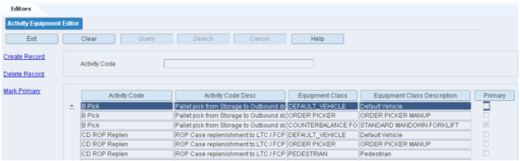
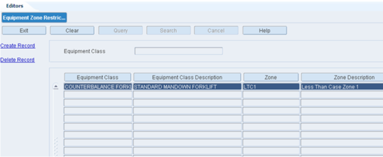
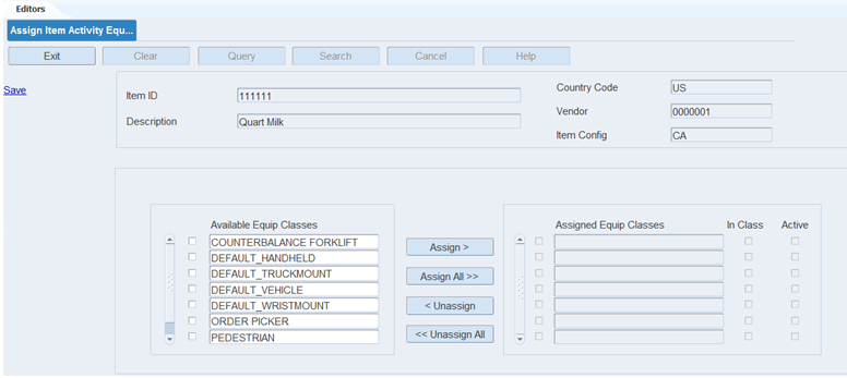
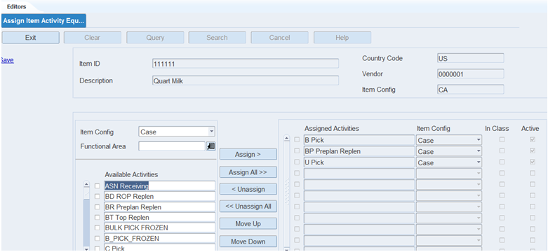
The Activity Equipment Editor allows you to associate one or more equipment classes to an activity. The system requires that one Equipment Class be designated as primary.
To access the Activity Equipment Editor window, navigate to Setup - Activity -> Activity Equipment Editor. The Activity Equipment Editor window opens.
Display All Activity Equipment Assignments
Click the Search button.
Display a Subset of Activity Equipment Assignments
Click the Query button.
To search for activity equipment by activity, enter the name of the activity in the Activity Code field, or click the LOV button and select the activity.
Click the Search button. The activity equipment assignments that match the search criterion appear.
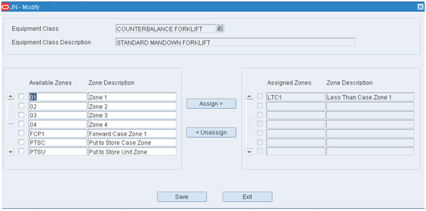
Edit an Activity Equipment Assignment
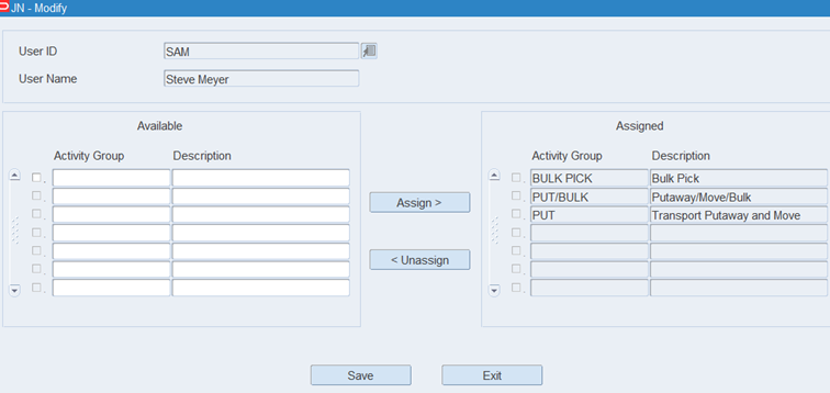
On the Activity Equipment Editor window, double-click the assignment that you want to edit. The Modify window opens.
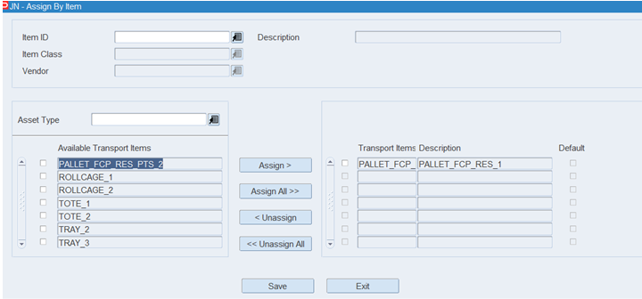
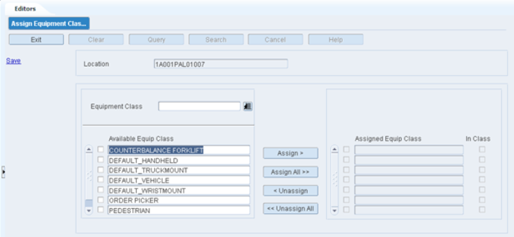
To add an Equipment Class to an Activity, place a check next to the Equipment Class on right side of screen and then Click Assign to place them on the left side of the screen.
To remove an Equipment Class from an Activity, place a check next to the Equipment Class on the left side of the screen and then click Unassign to place them on the right side of the screen.
Click Save to save any changes and close the Modify window.
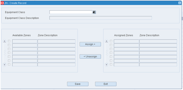
Add an Activity Equipment Assignment
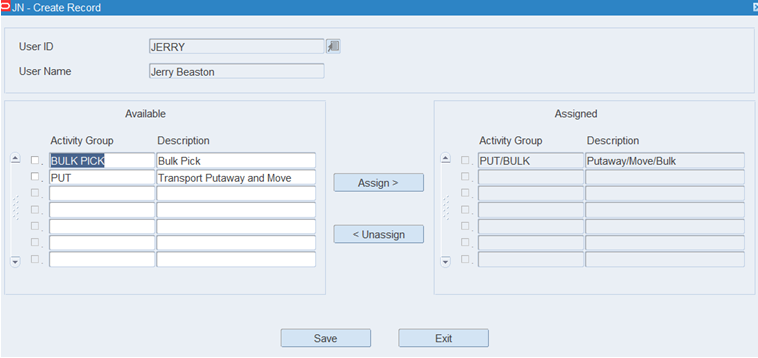
On the Activity Equipment Editor window, click Create Record. The Create Record window opens.
In the Activity Code field, enter the code for the activity, or click the LOV button and select the activity. When the Activity Code is selected the system automatically displays the Activity Code Description and the Available Equipment Classes with their descriptions.
To add an Equipment Class to an Activity, place a check next to the Equipment Class on right side of screen and then click Assign to place them on the left side of the screen.
To remove an Equipment Class from an Activity, place a check next to the Equipment Class on the left side of the screen and then click Unassign to place them on the right side of the screen.
Click Save to save the changes and close the Create Record window.
Delete an Assignment
On the Activity Equipment Editor window, select the assignment that you want to delete.
Click Delete Record.
When prompted to delete the record, click Yes.
Exit the Activity Equipment Editor Window
Click the Exit button to close the window.
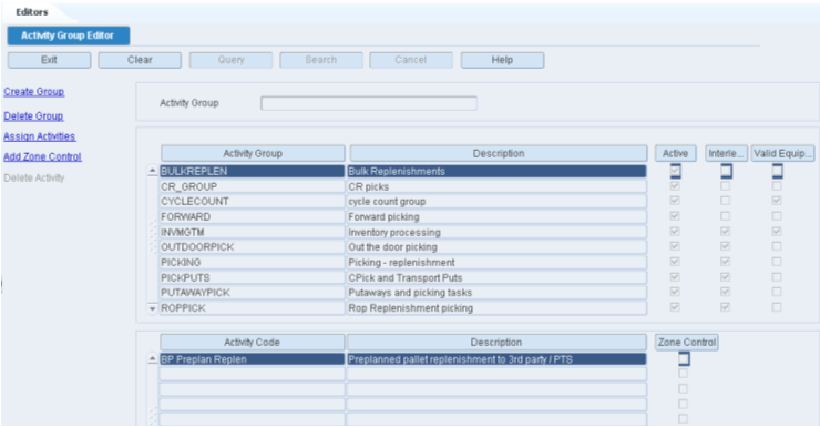
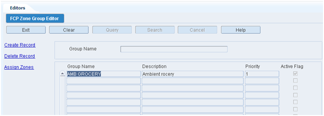
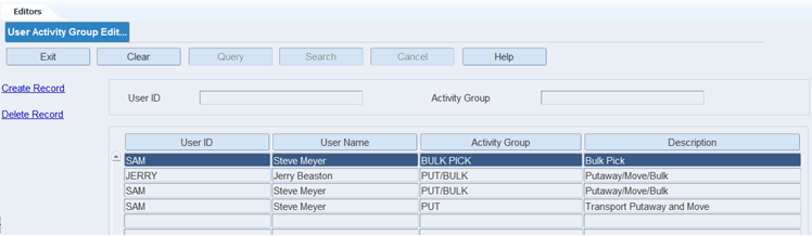
An Activity Group is a group of one or more defined activities which are given a group name. One activity can make up an entire group. The same activity can exist in multiple groups.
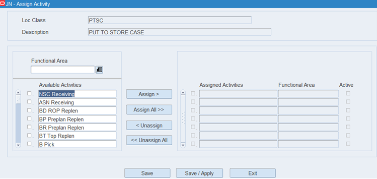
The Activity Group Editor allows you to group individual activities to allow activity interleaving.
The Zone Control Editor, which is accessible through the Activity Group Editor, allows you to define home zones for each activity in the group. If zone control is not defined, the activities with lowest priority and nearest proximity order are assigned to those users with permission to perform the activity across all available zones. If zone control is defined, the outstanding activities in the zone are sequenced according to the priority before assigning them to the users.
Activity groups and zone control do not determine the priority for an activity. The assignment of zone control to an activity in an activity group limits where the user assigned to that activity group can perform the activity.
To access the Activity Group Editor window, navigate to Setup - Activity -> Activity Group Editor. The Activity Group Editor window opens.
Display All Activity Groups
Click the Search button.
Display an Activity Group
If any activity group is currently displayed, click the Clear button.
Click the Query button.
In the Activity Group field, enter the code for the activity group, or click the LOV button and select the activity group.
Click the Search button. The activities associated with the selected activity group appear in the Activity Group table. The activity codes associated with an activity group appear in the Activity Code table.
Edit an Activity Group
|
Note: You can also edit the activities in an activity group using the Assign Activities link in the Activity Group Editor window. |
On the Activity Group Editor window, double-click the activity group record that you want to edit. The Modify window opens.
Edit the Description field as necessary.
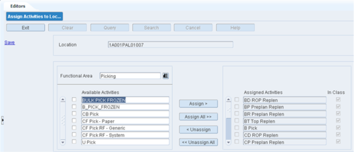
To assign new activities to the activity group, select the activities from the Available Activities table using the check box and move them to Assigned Activities table using the Assign button.
To remove the activities from the Assigned Activities table, select the activities using the check box and remove them using the Unassign button.
Click Save to save any changes and close the Modify window.
Add an Activity Group
On the Activity Group Editor window, click Create Group. The Create Group window opens.
In the Activity Group field, enter the code for a new activity group.
In the Description field, enter the description of the task group.
Select the Active check box to make the group active.
To assign activities to the activity group, select the activities from the Available Activities table using the check box and move them to Assigned Activities table using the Assign button.
To remove the activities from the Assigned Activities table, select the activities using the check box and remove them using the Unassign button.
Click Save to save the changes and close the Create Record window.
Add Zone Control to an Activity
|
Note: To access the Zone Control Editor window, you can also double-click the Activity Code displayed for the selected Activity Group. |
On the Activity Group Editor window, select the activity for which zones must be assigned.
Click Add Zone Control link. The Zone Control Editor window is displayed.
On the Zone Control Editor window, select the activity from the Available Activities table using the check box and move it to Activity table using the Assign button.
Select the Source Zone and Destination Zone for the activity using the LOVs.
Click Save to save the changes and exit the Zone Control Editor window.
Delete an Activity from an Activity Group
On the Activity Group Editor window, for an Activity Group, select the activity that you want to delete from the Activity Code table.
Click Delete Activity.
When prompted to delete the record, click Yes.
Delete an Activity Group
On the Activity Group Editor window, select the activity group record that you want to delete from the Activity Group table.
Click Delete Group.
When prompted to delete the record, click Yes.
Exit the Activity Group Editor Window
Click the Exit button to close the window.
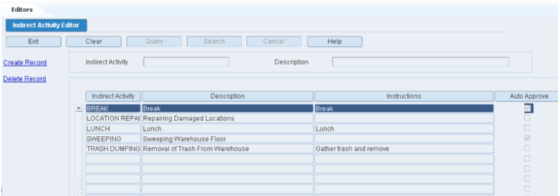
The Indirect Activity Editor allows you to define activities that are not normally tracked by the application. These Indirect Activities are normally performed by users without the use of a GUI or RF screen, for example: sweeping, facility maintenance, housekeeping, lunch, breaks. Once these Indirect Activities are defined, the application provides additional screens to capture the User ID, Start Time, and End Time for each Indirect Activity so the actual time spent on these activities can be reported.
To access the Indirect Activity Editor, navigate to Setup - Activity -> Indirect Activity Editor. The Indirect Activity Editor window opens.
Display All Indirect Activities
Click the Search button.
Display a Subset of Indirect Activities
If any indirect activity is currently displayed, click the Clear button.
Click the Query button.
In the Indirect Activity field, enter the name of the indirect activity, or click the LOV button and select the indirect activity.
Click the Search button. The indirect activities matching the selection criterion are displayed.
Edit an Indirect Activity
On the Indirect Activity Editor window, double-click the indirect activity you want to edit. The Modify window opens.
Modify the Description as needed.
Modify the Instructions as needed.
Check the Auto Approve flag as needed.
Click Save to save any changes and close the Modify window.
Create an Indirect Activity
On the Indirect Activity Editor window, click Create Record. The Create Record window opens.
In the Indirect Activity field, enter a name for the indirect activity.
In the Description field, enter the long description for the indirect activity.
In the Instructions field, enter the user instructions on how to perform the indirect activity.
In the Auto Approve field, check the flag if the indirect activity is approved without manager approval. If this indirect activity requires manager approval leave this flag unchecked. The Auto Approve flag is unchecked by default.
|
Note: The indirect activities can be approved by the manager using the Indirect Task Maintenance screen. |
Click Save to save the changes and close the Create Record window.
Delete an Indirect Activity
On the Indirect Activity Editor window, select the indirect activity you want to delete.
Click Delete Record.
When prompted to delete the record, click Yes.
Exit the Indirect Activity Editor Window
Click the Exit button to close the window.
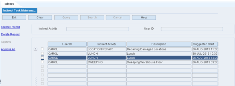
The Indirect Task Maintenance screen allows you to assign a defined indirect activity to a user ID and indicate a start and stop time. A manager or a supervisor can assign a specific user to an indirect activity and indicate a start time.
You can view the indirect activities assigned to your user ID. The actual start and end time for that activity can then be entered. The activity can be started before or after the suggested start time.
|
Note: Any RF indirect activity started also is displayed on the Indirect Task Maintenance screen and can be finished (by entering the stop time). |
The Indirect Task Maintenance screen works for two different security levels. For employees, the Approved Flag column is disabled. For managers and supervisors, the Approved Flag column is enabled. The manager/supervisor can modify the start time, stop time, and Approved Flag check box. When approved, the activity is written to the Activity History file and then deleted from this editor.
To access the Indirect Task Maintenance Editor window, navigate to Setup - Activity -> Indirect Task Maintenance. The Indirect Task Maintenance Editor window opens.
|
Note: An employee can update/create/delete only his own record. Managers/Supervisors can update records for all users till the indirect activities are approved. |
Display an Indirect Activity Assignment
If any indirect activity is currently displayed, click the Clear button.
Click the Query button.
To search by indirect activity, enter the indirect activity name in the Indirect Activity field, or click the LOV and select an indirect activity.
To search by user ID, enter the user ID in the User ID field, or click the LOV and select a User ID.
Click the Search button.
The user IDs and the assigned indirect activities that match the selection criterion are displayed.
Modify an Indirect Activity Assignment
On the Indirect Task Maintenance screen, double-click the record you want to modify. The Modify window opens
Change the enabled fields as necessary.
|
Note: A record can be updated/modified till it is approved. |
Click Save to save the changes and close the Modify window.
Create an Indirect Activity Assignment
On the Indirect Task Maintenance screen, click Create Record. The Create Record window opens.
In the User ID field, enter the user ID, or click the LOV button and select the user ID.
In the Indirect Activity field, enter the name of the indirect activity, or click the LOV and select the indirect activity.
Enter the values in the Suggested Start Time, Suggested End Time, Comment fields.
|
Note: The dates in the Suggested Start Time and Suggested End Time fields must be future dates. |
Click Save to save the changes and close the Create Record window.
Approve an Indirect Activity
|
Note:
|
On the Indirect Task Maintenance window, select the check box for a record or multiple records and click Approve.
To approve all the records, click Approve All.
|
Note: Approve All option approves only those records which are ready for approval. The other records are skipped. |
Delete an Indirect Activity Assignment
On the Indirect Task Maintenance window, select the record you want to delete.
Click Delete Record.
When prompted to delete the record, click Yes.
Exit the Indirect Task Maintenance Window
Click the Exit button to close the window.
The Setup - Administration is used to configure system level functions, such as facilities, menus, print queues, system parameters, translations, user messages, users, and working days.
This section includes the following topics:
System administration tasks are performed by system administrators or users with a high privilege level.
The administration setup module allows you to set up parameters that affect the entire system. You can set up the following:
System parameters: Determine which features should be operational and enter the default settings for various areas of the system.
Facilities: Create or copy the environments in which users must work.
Translations: Identify the supported languages. Translate menu options, field labels, and user messages.
Currencies and tickets: Identify and set up the format for currencies. Identify the ticket types, their printer queues, and default print quantities.
Codes: Translate inventory disposition codes, stock order upload codes, and transaction codes in order to make them compatible with host systems.
Printers and reports: Identify the types of output devices that are available to the system. Set default parameters for generating reports.
Work days: Identify the work days, non-work days, and hours of operation for the distribution center.
Process configurations: Identify how processes may be presented to users. Set up label configurations which may be assigned to processes presented as Label. Review the function keys found on RF screens.
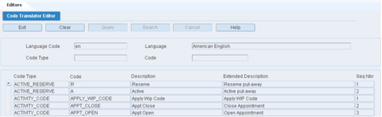
The Code Translator Editor allows you to associate a long description for the system defined codes. These codes are defined while coding the system and users cannot add or delete these codes.
To access the Code Translator Editor, navigate to Setup - Administration -> Code Translator Editor. The Code Translator Editor window opens.
Display the Code Type
On the Code Translator window, enter the Language Code.
Enter the Code Type and Code.
The Code Type, Code, Description, and Extended Description are displayed.
Exit Code Translator Window
Click the Exit button to close the window.
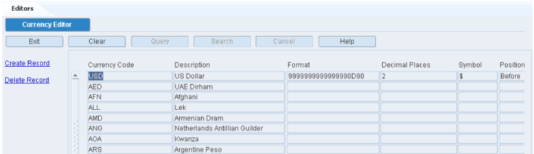
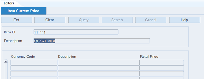
The Currency Editor allows you to add, modify, and delete currency codes in the system. The system provides the ability to format each currency. Currency information is used when prices are printed on tickets.
To access the Currency Editor, navigate to Setup - Administration -> Currency Editor. The current currency codes appear in the Currency Editor window.
Edit a Currency Code
On the Currency Editor window, double-click the currency that you want to edit. The Modify window opens.
Edit the description and formatting instructions as necessary.
Click Save to save the changes and close the Modify window.
Add a Currency Code
On the Currency Editor window, click Create Record. The Create Record window opens.
In the Currency Code and Description fields, enter the code and description for the currency.
In the Decimal Places field, enter the number of decimal places used in the currency. The number may 0, 1, or 2.
In the Symbol field, enter the symbol used for the currency. (For example: $ for US dollars.)
In the Sequence field, enter a number that represents where the currency code is printed on tickets.
In the Before or After field, enter B (before) or A (after) to indicate whether the symbol should appear before or after monetary amounts.
Click Save to save the changes and close the Create Record window.
Delete a Currency Code
On the Currency Editor window, select the currency code that you want to delete.
Click Delete Record.
When prompted to delete the record, click Yes.
Exit the Currency Editor Window
Click the Exit button to close the window.
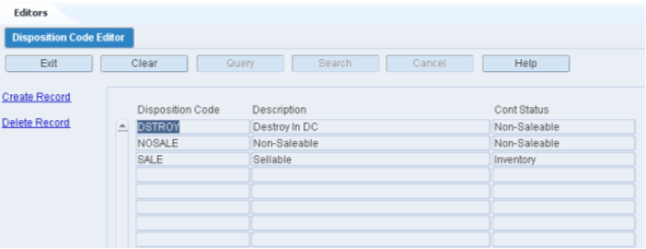
The Disposition Editor allows you to add, modify, and delete inventory disposition codes used for returns. These codes are user definable but must be synchronized with your host management system and/or Order Orchestration System. Disposition codes indicate what is to be done with merchandise that is returned by the customer.
To access the Disposition Code Editor, navigate to Setup - Administration -> Disposition Code Editor. The current disposition codes appear in the Disposition Editor window.
Edit a Disposition Code
On the Disposition Code Editor window, double-click the disposition code that you want to edit. The Modify window opens.
Edit the description and container status as necessary.
Click Save to save any changes and close the Modify window.
Add a Disposition Code
On the Disposition Code Editor window, click Create Record. The Create Record window opens.
In the Disposition Code and Description fields, enter a code and description for the disposition.
In the Cont Status field, enter the status of containers associated with the disposition code. The status may be I (Inventory) or N (Nonsaleable).
Click Save to save the changes and close the Create Record window.
Delete a Disposition Code
On the Disposition Editor window, select the disposition code that you want to delete.
Click Delete Record.
When prompted to delete the record, click Yes.
Exit the Disposition Editor Window
Click the Exit button to close the window.
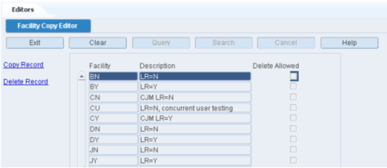
The Facility Copy Editor allows you to copy a facility and create a new facility in RWMS. When you copy a facility, you copy the data from an existing facility. You cannot delete the facilities that were installed with the system. You can, however, delete facilities that were added by users provided that the Delete Allowed option was selected for the facility upon setup.
To access the Facility Copy Editor, navigate to Setup - Administration -> Facility Copy Editor. The current facilities appear in the Facility Copy Editor window.
Edit a Facility
On the Facility Copy Editor window, double-click the facility that you want to edit. The Modify window opens.
Edit the description as necessary.
Click Save to save the change and close the Modify window.
Add a Facility
|
Note: At least one facility must already be set up in the system, as new facilities are copied from an existing facility. |
On the Facility Copy Editor window, click Copy Record. The Copy Record window opens.
In the From Facility field, enter the ID of the facility to be copied.
In the Facility and Description fields, enter the ID and name of the new facility.
In the Delete Allowed field, enter Y (Yes) if the facility may be deleted. Otherwise, enter N (No).
Click Save to save the changes and close the Copy Record window.
Delete a Facility
On the Facility Copy Editor window, select the facility that you want to delete.
Click Delete Record.
When prompted to delete the record, click Yes.
Exit the Facility Copy Editor Window
Click the Exit button to close the window.
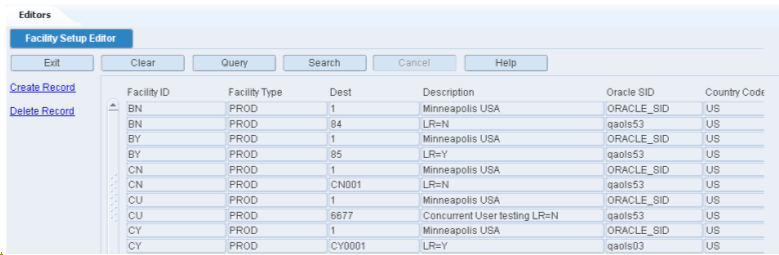
The Facility Setup Editor window allows you to create and maintain facilities. You can edit the following parameters for a facility: type, country, or labeled reserve attributes. It is recommended that three facilities be set up in RWMS: Production (PR), Testing (TS), and Training (TR). The Production facility is pre-installed in RWMS and cannot be deleted. The user chooses the appropriate facility when logging on to the system. Any changes they make to the system are applied to the selected facility only.
To access the Facility Setup Editor, navigate to Setup - Administration -> Facility Setup Editor. The current facilities appear in the Facility Setup Editor window.
Edit a Facility
On the Facility Setup Editor window, double-click the facility that you want to edit. The Modify window opens.
Edit the enabled fields as necessary.
Click Save to save any changes and close the Modify window.
Add a Facility
On the Facility Setup Editor window, click Create Record. The Create Record window opens.
In the Facility field, enter the ID of the facility.
In the Facility Type field, enter the code for the type of facility.
In the Dest field, enter the destination ID of the distribution center, or click the LOV button and select the destination.
In the Description field, enter a description of the facility.
In the Oracle SID field, enter the Oracle system ID of the facility.
In the Country Code field, enter the code for the country in which the facility is located, or click the LOV button and select the country.
In the Allow Opposite Labeled Reserve field, enter Y (Yes) or N (No) to indicate whether the facility accepts shipments from a facility that uses opposite labeled reserve.
In the Labeled Reserve field, enter Y (Yes) or N (No) to indicate whether the facility uses labeled reserve functionality.
Click Save to save the changes and close the Create Record window.
Delete a Facility
On the Facility Setup Editor window, select the facility that you want to delete.
Click Delete Record.
When prompted to delete the record, click Yes.
Exit the Facility Setup Editor Window
Click the Exit button to close the window.
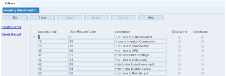
The Inventory Adjustment Reason Code Editor allows you to associate user-defined reason codes with reason codes defined in RWMS. Inventory Adjustment Reason codes are codes that provide a description as to why the adjustment is being made.The user defined reason codes must synchronize with the reason codes on the host system.
To access the Inventory Adjustment Reason Code Editor, navigate to Setup - Administration -> Inventory Adjustment Reason Code Editor. The current reason codes appear in the Inventory Adjustment Reason Code Editor window.
Edit a Reason Code
On the Inventory Adjustment Reason Code Editor window, double-click the reason code that you want to edit. The Modify window opens.
Edit the Description and Display Ind as necessary.
Click Save to save any changes and close the Modify window.
Add a Reason Code
On the Inventory Adjustment Reason Code Editor window, click Create Record. The Create Record window opens.
In the Reason Code field, enter a reason code that you want to translate, or click the LOV button and select the reason code.
In the User Reason Code and Description fields, enter a user-defined code and description for the reason.
To allow users to view the reason code in List of Values windows, select the Display Ind check box.
Click Save to save the changes and close the Create Record window.
Delete a Reason Code
On the Inventory Adjustment Reason Code Editor window, select the reason code that you want to delete.
Click Delete Record.
When prompted to delete the record, click Yes.
Exit the Inventory Adjustment Reason Code Editor Window
Click the Exit button to close the window.
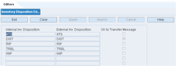
The Inventory Disposition Editor allows you to associate external (host system) inventory disposition codes with disposition codes provided by RWMS. In addition to translating the RWMS system code, you can indicate whether a message should be transmitted in order to notify the host system of the change.
To access the Inventory Disposition Editor, navigate to Setup - Administration -> Inventory Disposition Editor. The current codes appear in the Inventory Disposition Editor window.
Edit a Disposition Code
On the Inventory Disposition Editor window, double-click the code that you want to edit. The Modify window opens.
Edit the External Inv Disposition field as necessary.
To indicate that a message should be sent to the host system, select the OK to Transfer Message check box.
Click Save to save any changes and close the Modify window.
Exit the Inventory Disposition Editor Window
Click the Exit button to close the window.
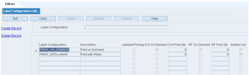
The Label Configuration Editor allows you to maintain a list of label configurations. A label configuration provides the system with the instructions needed to print the correct label type to the desired printer.
To access the Label Configuration Editor, navigate to Setup - Administration > Label Configuration Editor. The Label Configuration Editor window opens.
Display All Label Configurations
Click the Search button.
Display a Label Configuration
If any label configurations are currently displayed, click the Clear button.
Click the Query button.
In the Label Configuration query field, enter the name of the label configuration, or click the LOV button and select the label configuration.
Click the Search button. The label configuration that matches the search criterion opens.
|
Note: If you enter a partial name in the Label Configuration query field, all label configurations that begin with the same characters are displayed. |
Edit a Label Configuration
On the Label Configuration Editor window, double-click the label configuration that you want to edit. The Modify window opens.
|
Note: You cannot edit a label configuration if the system indicator is selected. |
Edit the enabled fields as necessary.
Click Save to save the changes and close the Modify window.
Add a Label Configuration
On the Label Configuration Editor window, click Create Record. The Create Record window opens.
In the Label Configuration and Description fields, enter a name and description for the label configuration.
Select Labeled Picking if necessary for the task.
Select GUI on Demand if you prefer that labels be printed for a GUI user only when requested.
In the GUI Print Qty field, enter the number to be printed.
Select RF on Demand if you prefer that labels be printed for an RF user only when requested.
In the RF Print Qty field, enter the number to be printed.
Click Save to save the changes and close the Create Record window.
Delete a Label Configuration
On the Label Configuration Editor window, select the label configuration that you want to delete.
|
Note: You cannot delete a label configuration if the system indicator is selected. |
Click Delete Record.
When prompted to delete the record, click Yes.
Exit the Label Configuration Editor Window
Click the Exit button to close the window.
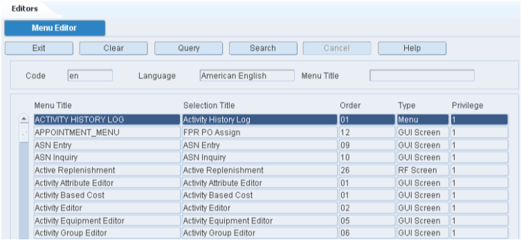
The Menu Editor allows you to view the system supported Menu's and associate a user defined menu title, user privilege level, and the order in which this menu option should appear on main menu.
To access the Menu Editor, navigate to Setup - Administration -> Menu Editor. The menu options appear in the Menu Editor window.
|
Note: You can also access this window from the Supported Language window. |
Display the Menu Options
If any menu options are currently displayed, click the Clear button.
Click the Query button.
In the Code query field, enter the code for the language, or click the LOV button and select the language.
Click the Search button. The menu options associated with the selected language appear.
Edit a Translation
On the Menu Editor window, double-click the menu option that you want to edit. The Modify window opens.
Edit the title, its order on the menu, and its user privilege level as necessary.
Click Save to save any changes and close the Modify window.
Delete a Menu Option
On the Menu Editor window, select the menu option that you want to delete.
Click Delete Record.
When prompted to delete the record, click Yes.
Exit the Menu Editor Window
Click the Exit button to close the window.
The Print Queue Editor allows you to maintain a list of network printers to which reports and labels may be sent for printing.
You can enter multiple print queues, but only one file queue and one screen queue may be entered. Output may be directed to the following destinations:
Screen: Output opens on the monitor.
File: Output is saved to a file.
Printer: Output is directed to the designated printer.
To access the Print Queue Editor window, navigate to Setup - Administration -> Print Queue Editor. The current print queues appear in the Print Queue Editor window.
Edit a Print Queue
On the Print Queue Editor window, double-click the print queue that you want to edit. The Modify window opens.
Edit the type and description as necessary.
Click Save to save any changes and close the Modify window.
Add a Print Queue
On the Print Queue Editor window, click Create Record. The Create Record window opens.
In the Dest field, enter the destination. The destination may be Printer, File, or Screen.
In the Queue field, enter the name of the print queue. If the Destination is File or Screen, the Queue defaults to None.
In the Description field, enter the description of the print queue.
In the Location field, enter the location ID of the printer or click the LOV to select a location.
Click Save to save the changes and close the Create Record window.
Delete a Print Queue
On the Print Queue Editor window, select the print queue that you want to edit.
Click Delete Record.
When prompted to delete the record, click Yes.
Exit the Print Queue Editor Window
Click the Exit button to close the window.
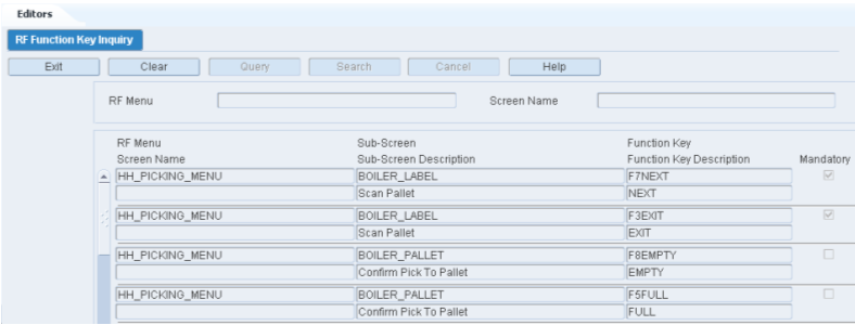
The RF Function Key Inquiry allows you to view the function keys that appear on each screen of radio frequency (RF) devices. A screen may be composed of one or more sub-screens that have the same function keys.
Knowing which function keys are mandatory on RF screens becomes useful when you assign RF screens to a process type.
To access the RF Function Key Inquiry window, navigate to Setup - Administration -> RF Function Key Inquiry. The RF Function Key Inquiry window opens.
Display All RF Screens
Click the Search button.
Display a Subset of RF Screens
If any RF screens are currently displayed, click the Clear button.
Click the Query button.
To display RF screens associated with a menu, enter the name of the menu in the RF Menu query field, or click the LOV button and select the menu. To display a screen and any related sub-screens, enter the name of the RF screen in the Screen Name query field, or click the LOV button and select the RF screen.
Click the Search button. The RF screens that match the search criteria appear.
Exit the RF Function Key Inquiry Window
Click the Exit button to close the window.
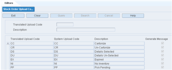
The Stock Order Upload Code Editor allows you to associate external Stock Order Upload Codes used by the host system to existing Codes provided by RWMS. In addition to translating the system code, you can indicate whether a message should be transmitted in order to notify the host system of the change.
To access the Stock Order Upload Code Editor, navigate to Setup - Administration -> Stock Order Upload Code Editor. The current codes appear in the Stock Order Upload Code Editor window.
Edit a Stock Order Upload Code
On the Stock Order Upload Code Editor window, double-click the code that you want to edit. The Modify window opens.
Edit the translated upload code as necessary.
To indicate that a message should be sent to the host system, select the Generate Message check box.
Click Save to save any changes and close the Modify window.
Exit the Stock Order Upload Code Editor Window
Click the Exit button to close the window.
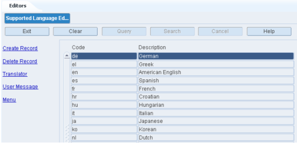
The Supported Language Editor allows you to view a list of language codes supported by the system. After a language is identified, you can access the following windows in order to translate a variety of system elements:
Translation Editor: Displays the field labels used in RWMS.
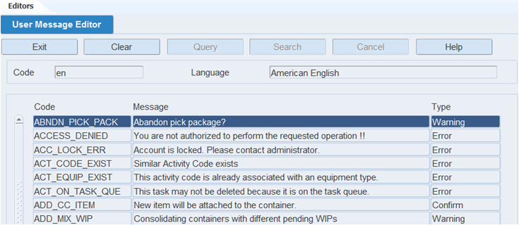
User Message Editor: Displays the user messages found in RWMS.
Menu Editor: Displays the menu options used in RWMS.
Users will see field labels, user messages, and menu options in the language that is associated with their user IDs.
To access the Supported Language Editor window, navigate to Setup - Administration -> Supported Language Editor. The current language codes appear in the Supported Language window.
Edit a Language Code
On the Supported Language window, double-click the language code that you want to edit. The Modify window opens.
Edit the description as necessary.
Click Save to save any changes and close the Modify window.
Add a Language Code
On the Supported Language window, click Create Record. The Create Record window opens.
In the Code field, enter the standard code for the language.
In the Description field, enter the name of the language.
Click Save to save the changes and close the Create Record window.
Delete a Language Code
On the Supported Language window, select the language code that you want to delete.
Click Delete Record.
When prompted to delete the record, click Yes.
Display the Menu
On the Supported Language window, select the language code and click Menu. The Menu Editor window opens.
The menu title in English, the corresponding title in Portuguese-Brazil, the order and the privilege are displayed.
Edit Menu
On the Menu Editor window, double click the field you want to edit. The Modify window opens.
Edit the description as necessary.
Click Save to save the changes and Exit/Cancel to exit the window.
Translating the Data Base Value
On the Supported Language Editor, select the language and click Translator. The Translation Editor window opens.
The database value in English and the corresponding value in the selected language is displayed.
User Message Editor
On the Supported Language Editor, select the language and click User Message. The User Message Editor window opens.
Click the list of value to choose the language and click the Search button.
The message is displayed in the selected language. In addition, the type of message is displayed.
Exit the Supported Language Window
Click the Exit button to close the window.
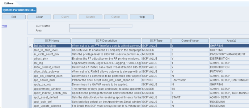
The System Parameters Editor allows you to view and modify the supported system parameters. System Parameters are individual value settings that change how processes are performed in the warehouse. Each warehouse facility must review and set the system parameters based on their desired process flow.
System parameters are grouped by functional area. If a parameter may be used in more than one functional area, it is grouped with the most affected area. You can choose to display system parameters by description or by functional area.
System parameters are defined when installed. You cannot add or delete a parameter. You can edit the current value, the functional area, and whether or not the parameter should be used by the system.
Only users with a high privilege level (privilege level 8 and 9) may edit system parameters.
To access the System Parameters Editor, navigate to Setup - Administration -> System Parameters Editor. The System Parameters Editor window opens.
Display All System Parameters
Select the sort order:
Sort by Description: Sorts the system parameters in alphabetical order by description.
Sort by Area: Sorts the system parameters in alphabetical order by functional area.
Click the Search button. The system parameters appear in the selected sort order.
Display System Parameters by Description or Functional Area
If any system parameters are currently displayed, click the Clear button.
Click the Query button.
To search for system parameters by:
Description: Enter all or part of the description in the System Parameter query field, or click the LOV button and select the system parameter.
Functional area: Enter all or part of the area name in the Area query field, or click the LOV button and select the area.
|
Note: You can use the percent (%) symbol as a wildcard character. |
Click the Search button. The system parameters that match the search criterion appear.
Edit System Parameters
On the System Parameters Editor window, double-click the system parameter that you want to edit. The Modify window opens.
Edit the current value and functional area as necessary.
In the In Use field, enter Y (Yes) to turn on or N (No) to turn off a system parameter as necessary.
Click Save to save any changes and close the Modify window.
Exit the System Parameters Editor Window
Click the Exit button to close the window.
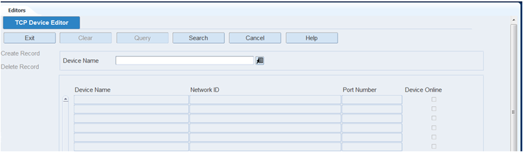
The TCP Device Editor allows you to set up an interface between RWMS and a Cubiscan device. Cubiscan devices provide RWMS with the dimensional and weight information needed to optimize loads for packing and shipment.
To access the TCP Device Editor, navigate to Setup - Administration -> TCP Device Editor. The TCP Device Editor window opens.
Display all TCP Devices
Click the Search button.
Display a TCP Device
If any TCP parameters are currently displayed, click the Clear button.
Click the Query button.
To search for TCP Device, enter the name of the Cubiscan device in the Device Name query field, or click the LOV button and select the device.
Click the Search button. The TCP Device that matches the search criteria appear.
Edit a TCP Device
On the TCP Device Editor window, double-click the TCP Device that you want to edit. The Modify window opens.
Edit the enabled fields as necessary.
Click Save to save the changes and close the Modify window.
Add a TCP Device
Click Create Record. The Create Record window opens.
In the Device Name field, enter the ID of the device you want to interface with.
In the Network ID field, enter the network ID the device is using.
In the Port Number field, enter the port the device is using.
If the device is online, select the Device Online check box.
In the Timeout field, enter the amount of time before the connection is lost.
Click Save to save your changes and close the Create Record window.
Exit the TCP Device Editor Window
Click the Exit button to close the window.
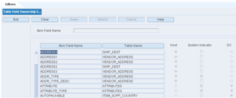
The Table Field Ownership Editor allows you to indicate whether the fields describing an item are owned by RWMS or by the host system.
The scenarios pertaining to field ownership are:
If a field is required by the host and is also a primary key in RWMS, it is automatically marked as owned by the host and the system indicator is selected. You cannot change the ownership of the field to the distribution center (DC).
If a field is normally owned by the host but is not a primary key in RWMS, it is automatically marked as owned by the host, but the system indicator is not selected. You can change the ownership to the DC.
All other fields may be marked as owned by the DC. If a field is owned by the DC, it is protected from modifications that are received from the host.
To access the Table Field Ownership Editor, navigate to Setup - Administration -> Table Field Ownership Editor. The Table Field Ownership window is displayed.
Display All Item Fields
Click the Search button.
Display an Item Field
If any Item Field Names are currently displayed, click the Clear button.
In the Item Field Name field, enter the item field name or click the LOV and select and item field name.
Click the Search button.
Modify an Item Field
On the Table Field Ownership Editor window, double-click the Item Field Name you want to edit. The Modify window opens.
Check the DC field as necessary.
Click Save to save the change and close the Modify window.
Exit the Table Field Ownership Editor Window
Click the Exit button to close the window.
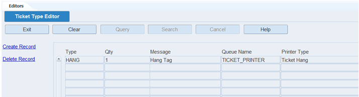
The Ticket Type Editor allows you to define and view a list of ticket types. You can enter a message, the maximum quantity, and printer information.
To access the Ticket Type Editor window, navigate to Setup - Administration -> Ticket Type Editor. The current ticket types appear in the Ticket Type Editor window.
Edit a Ticket Type
On the Ticket Type Editor window, double-click the ticket type that you want to edit. The Modify window opens.
Edit the enabled fields as necessary.
Click Save to save any changes and close the Modify window.
Add a Ticket Type
On the Ticket Type Editor window, click Create Record. The Create Record window opens.
In the Type field, enter the code for the ticket type.
In the Message field, enter the message to be printed with the ticket.
In the Ticket Qty field, enter the number of tickets to be printed.
In the Queue Name field, enter the name of the print queue, or click the LOV button and select the print queue.
In the Printer Type field, enter the name of the printer.
Click Save to save the changes and close the Create Record window.
Delete a Ticket Type
On the Ticket Type Editor window, select the ticket type that you want to delete.
Click Delete Record.
When prompted to delete the record, click Yes.
Exit the Ticket Type Editor Window
Click the Exit button to close the window.
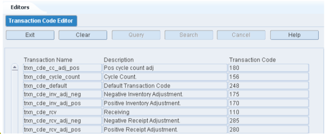
The Transaction Code Editor allows you to view the RWMS supported inventory transaction names and codes. The user can change the code for a transaction name to match a code in the connected host management system.
To access the Transaction Code Editor window, navigate to Setup - Administration -> Transaction Code Editor. The current transaction codes appear in the Transaction Code Editor window.
Edit a Transaction Code
On the Transaction Code Editor window, double-click the transaction code that you want to edit. The Modify window opens.
Edit the description and transaction code as necessary.
Click Save to save the change and close the Modify window.
Exit the Transaction Code Editor Window
Click the Exit button to close the window.
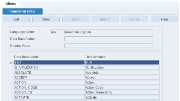
The Translation Editor allows you to view the data base values in English and then the translated value in the language selected. Users can modify the translated value if necessary.
To access the Translation Editor, navigate to Setup - Administration -> Translation Editor. The Translation Editor window opens.
|
Note: You can also access this window from the Supported Language window. |
Display the Field Labels
If any values are currently displayed, click the Clear button.
Click the Query button.
In the Code query field, enter the code for the language, or click the LOV button and select the language.
Click the Search button. The values associated with the selected language appear.
Edit a Translation
On the Translation Editor window, double-click the value that you want to edit. The Modify window opens.
Edit the value as necessary.
Click Save to save any changes and close the Modify window.
Exit the Translation Editor Window
Click the Exit button to close the window.
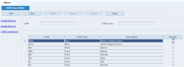
Unit of measure classes represent groups of units of measure with similar characteristics. The UOM Class Editor allows for the creation and viewing of UOM Classes and their associated specific Units of Measure. RWMS is delivered with a standard list of Oracle UOM classes (Area, Configuration, Dimension, LVolume, Mass, Miscellaneous, Pack, Qty, Speed, Time, and Volume). The Editor allows for the creation of new UOMs that can be associated to existing UOM classes. User created UOMs are the only UOMs that can get deleted.
To access the UOM Class Editor, navigate to Setup - Administration -> UOM Class Editor. The UOM Class Editor window opens.
Display All UOM Classes
Click the Search button.
Display a Subset of UOM Classes
Click the Query button.
To search for a single UOM, enter specific UOM in the UOM query field, or click the LOV button and select the UOM. To search for a specific UOM Class, enter the name of the UOM Class in the UOM Class query field, or click the LOV button and select the UOM Class.
Click the Search button. The UOM Classes that match the search criteria appear.
Edit a UOM Class
The system does not allow for the modification of existing UOM Classes. If the UOM class was created by a user it can be deleted.
Add a New UOM to an Existing UOM Class
On the UOM Class Editor window, click Create Record. The Create Record window opens.
In the UOM field, enter the name of the Unit of Measure being created.
In the UOM Class field, enter the UOM Class or click the LOV button and select the UOM Class desired. The system will not allow the creation of a new UOM Class.
In the Description field, enter the specific description of the UOM.
In the Display field. Click yes if you want this UOM displayed on screen.
Click Save to save the changes and close the Create Record window
Delete a UOM
On the UOM Class Editor window, select the UOM that you want to delete. The UOM must be user defined to allow delete.
Click Delete Record.
When prompted to delete the record, click Yes.
Exit the UOM Class Editor Window
Click the Exit button to close the window.
The UOM Conversion Editor allows you to view the From UOM and the To UOM with the mathematical factor required for conversion.
To access the UOM Conversion Editor, navigate to Setup - Administration -> UOM Conversion Editor. The UOM Conversion Editor window opens.
Display All UOM Conversions
Click the Search button.
Display a Subset of UOM Conversions
Click the Query button.
To search for a specific From UOM, enter the UOM in the From UOM field, or click the LOV button and select the UOM. To search for a specific To UOM, enter the UOM in the To UOM field, or click the LOV button and select the UOM.
Click the Search button. The UOMs that match the search criteria appear.
Add, Modify and Delete of a UOM Conversion
The system prohibits the adding, modification, or deleting of a UOM Conversion. This data is pre loaded into the application.
Exit the UOM Class Editor Window
Click the Exit button to close the window.
The Working Days Editor allows you to define the working days and appointment window within each working day for your specific facility. Upon installation of the RWMS software a range of working days must be defined for the software to function. From the Working Day Editor you can jump to the Shift Editor by pressing the View Shifts link. The definition of shifts is optional in RWMS.
To access the Working Days Editor window, navigate to Setup - Administration -> Working Days Editor. The Working Days Editor window opens.
Display a Range of Dates
If any Dates are currently displayed, click the Clear button.
Click the Query button.
In the Date field, enter the start date, or click the calendar button and select the date.
Click the Search button. The dates from the selected date forward are displayed.
|
Note: The work day defaults are determined by system settings: Start Time, End Time, and whether Saturdays and Sundays are work days. You can override the default times when adding a work day. You can override the work day indicator when editing a record. |
Edit a Date
On the Working Days Editor window, double-click the work date that you want to edit. The Modify window is displayed.
Edit the Work Day indicator and Start and End times as necessary.
Enter appointment times as necessary. The Appointment Start and End Time is the range between which you can receive appointments. The appointment time needs to be between the Work Days time range.
Enter or edit a comment as necessary.
Click Save to save any changes and close the Modify window.
Add One or More Days
On the Working Days Editor window, click Create Record. The Create window opens.
To add one date, enter the same date in both the Start Date and End Date fields. To add a range of dates, enter the start date and end date in their respective fields.
Use the check boxes to indicate the working days over a calendar range.
In the Start Time and End Time fields, enter the times when the work day begins and ends. Use 24 hour international standard notation.
Enter Appt Start Time and Appt End Time as necessary.
Click Save to save the changes and close the Create window.
View Shift
The View Shifts link on the Working Days Editor window allows you to view the shifts and breaks associated to a working day.
On the Working Days Editor window, click View Shifts. The Shift Definition window opens.
If any Shift IDs are currently displayed, click the Clear button.
Click the Query button.
Select the Shift ID using the LOV button on the right. Click Search.
Select the Shift ID to view the breaks for the shift.
Exit the Working Days Editor Window
Click the Exit button to close the window.
The DC setup is used to set up the physical layout and container types in the distribution center. This includes defining DC departments, regions, location types, location attributes, and locations. Some types of locations, such as doors, forward pick locations, and put to store locations, require additional details. Common characteristics of locations may be defined at the location type level. Location classes can be used to group locations with similar defaults, processes, and equipment types. Unit pick systems can be set up and putaway plans can be defined.
This section includes the following topics:
The Aisle Editor allows you to create and review the aisles within your facility. An Aisle is defined as a walking or driving path (forklift) between storage or pick locations.
To access the Aisle Editor, navigate to Setup - DC > Aisle Editor. The Aisle Editor window opens.
Display All Aisles
Click the Search button.
Display an Aisle
If any aisles are currently displayed, click the Clear button.
Click the Query button.
In the Aisle field, enter the aisle, or click the LOV button and select the aisle.
Click the Search button. The aisle that match the search criterion opens.
Edit an Aisle
On the Aisle Editor window, double-click the aisle that you want to edit. The Modify window opens.
Edit the Description and Max Users fields as necessary.
Click Save to save any changes and close the Modify window.
Add an Aisle
On the Aisle Editor window, click Create Record. The Create Record window opens.
In the Aisle Field, enter the aisle designation (Alpha numeric up to 10 digits).
In the Description field, enter the desired long description for the aisle.
In the Max Users field, enter the maximum number of users that can be in the aisle at the same time. This is used in task management to prevent too many users being in the same aisle at the same time which reduces productivity.
Click Save to save any changes and close the Create Record window.
Delete an Aisle
On the Aisle Editor window, select the aisle that you want to delete.
Click Delete Record.
When prompted to delete the record, click Yes.
Exit the Aisle Editor Window
Click the Exit button to close the window.
The Carton Group Editor allows you to create and view the different types of cartons (containers) used in your warehouse operation.
To access Carton Group Editor, navigate to Setup - DC -> Carton Group Editor. The Carton Group Editor window opens.
Display All Carton Groups
Click the Search button.
Display a Carton Group
If any carton groups are currently displayed, click the Clear button.
Click the Query button.
In the Container Group field, enter the code for the carton group, or click the LOV button and select carton group.
Click the Search button. The container types in the selected carton group appear.
Edit a Carton Group
On the Carton Group Editor window, double-click the carton group that you want to edit. The Modify window opens.
Edit the Container Type as necessary.
Click Save to save any changes and close the Modify window.
Add a Carton Group
You can also use this procedure to add another container type to an existing carton group.
On the Carton Group Editor window, click Create Record. The Create Record window opens.
In the Container Group and Group Desc fields, enter a code and description for the carton group.
In the Container Type field, enter the code of the container type that you want to associate with the carton group, or click the LOV button and select the container type.
Click Save to save the changes and close the Create Record window.
Delete a Carton Group
You can also use this procedure to delete a container type from a carton group.
On the Carton Group Editor window, select the container group/container type record that you want to delete.
Click Delete Record.
When prompted to delete the record, click Yes.
Exit the Carton Group Editor Window
Click the Exit button to close the window.
The Container Type Editor allows you to define a master list of container types. You can enter the dimensions, tare weight, and unit cost. You also indicate how a container is determined to be full. The volume types are:
Cube: The container is full when it reaches its cubic capacity.
Unit: The container is full when the maximum number of standard units are placed in it.
A container is defined as something that holds merchandise and/or other containers. A container might be a tote, pallet, carton, trolley, hanger set, tanker, and so on.
To access the Container Type Editor, navigate to Setup - DC -> Container Type Editor. The current container types appear in the Container Type Editor window.
Edit a Container Type
On the Container Type Editor window, double-click the container type that you want to edit. The Modify window opens.
Edit the enabled fields as necessary.
Click Save to save any changes and close the Modify window.
Add a Container Type
On the Container Type Editor window, click Create Record. The Create Record window opens.
In the Type and Description fields, enter the code and description for the container type.
In the Length, Width, and Height fields, enter the dimensions of the container.
In the Tare Weight field, enter the weight of the empty container.
In the Volume Type field, enter Unit or Cube to indicate the method used to determine whether a container is full.
If the Volume Type is Unit, enter the number of standard units that would fill a container in the Max Std Units field.
In the Max Weight field, enter the maximum weight that the container type can hold.
In the Unit Cost field, enter the cost per unit.
Click Save to save the changes and close the Create Record window.
Delete a Container Type
On the Container Type Editor window, select the container type that you want to delete.
Click Delete Record.
When prompted to delete the record, click Yes.
Exit the Container Type Editor Window
Click the Exit button to close the window.
The Door Editor allows you to maintain shipping and receiving doors. Before setting up a door, be sure a location ID (with type as Shipping Door or Receiving Door) exists for the door as every door must be identified as a location. You can indicate whether a door is used for shipping, receiving, or both. You can also indicate the type of merchandise handled at a door, such as hanging, flat, shoe, or all.
The status of the door may be Available, Out of Service, or Busy. You can change the status from Available to Out of Service and back to Available as necessary.
Each receiving door may be associated with one or more load types. Load types are defined at the item level and can also be at the appointment level. In order for the system to recommend best fit doors for inbound trailers, the load types need to be defined.
To access the Door Editor, navigate to Setup - DC -> Door Editor. The current doors appear in the Door Editor window.
Edit a Door
On the Door Editor window, double-click the door that you want to edit. The Modify window opens.
Edit the enabled fields as necessary.
Click Save to save any changes and close the Modify window.
Add a Door
On the Door Editor window, click Create Record. The Create Record window opens.
In the Door field, enter the ID for the door.
In the Location ID field, enter the ID of the door's location, or click the LOV button and select the location.
In the Recv Ship field, enter the code for the door's function. The function may be R (Receiving), S (Shipping), or X (Both).
In the Door Ind field, enter the code for the type of merchandise handled at the door. The type may be H (Hanging), F (Flat), S (Shoe), or A (All).
Click Save to save the changes and close the Create Record window.
Delete a Door
On the Door Editor window, select the door that you want to delete.
Click Delete Record.
When prompted to delete the record, click Yes.
Change the Status of a Door
On the Door Editor window, select the door that you want to edit.
Click Service. If the status was Available, it becomes Out of Service. If it was Out of Service, it becomes Available.
The Door Zone Editor allows you to associate a receiving door to a storage zone so inbound merchandise is driven to that zone during the putaway process.
Each receiving door may be associated with one or more zones. When recommending/prioritizing doors for receiving appointments, the system considers item put-away zones for items on the appointment and select doors based on the number of items with matching zones.
The Door Zone Editor screen allows the user to create or delete a door zone record.
On the Door Editor window, select a door and click Zones. The Door Zone Editor window opens.
Create Record
On the Door Zone Editor window, click Create Record. The Create Record window opens.
Click the LOV button and select the zone.
Click Save to save any changes and close the Create Record window.
Delete a Record
On the Door Zone Editor window, select the door that you want to delete.
Click Delete Record.
When prompted to delete the record, click Yes.
Exit the Door Zone Editor Window
Click the Exit button to close the window.
The Door Load Type Editor window allows the user to set load types per door.
On the Door Editor window, select a door and click Load Types. The Door Load Type Editor window opens.
Create Record
On the Door Load Type Editor window, double-click the door that you want to create. The Create Record window opens.
Click the LOV button and select the load type.
Click Save to save any changes and close the Create Record window.
Delete a Record
On the Door Load Type Editor window, select the door that you want to delete.
Click Delete Record.
When prompted to delete the record, click Yes.
Exit the Door Load Type Editor Window
Click the Exit button to close the window.
Exit the Door Editor Window
Click the Exit button to close the window.
The Outbound Container Editor allows you to define and review the outbound container types used within your facility. These container types are used for consumer direct shipments and require the amount of collateral and dunnage that will be added to the container.
To access the Outbound Container Editor, navigate to Setup - DC -> Outbound Container Editor. The current outbound container types appear in the Outbound Container Editor window.
Edit an Outbound Container Type
On the Outbound Container Editor window, double-click the container type that you want to edit. The Modify window opens.
Edit the enabled fields as necessary.
Click Save to save any changes and close the Modify window.
Add an Outbound Container Type
On the Outbound Container Editor window, click Create Record. The Create Record window opens.
In the Container Type field, enter the ID of a container type, or click the LOV button and select the container type.
In the Owner field, enter the name of an owner if applicable. Otherwise, enter ALL.
In the Collateral Wgt field, enter the weight of advertisements, flyers, or other such materials that are expected to be included in the container.
In the Dunnage Wgt field, enter the weight of the packing materials.
In the Min Dunnage Wgt field, enter the least amount of dunnage expected.
In the In Service field, enter Y (Yes) to place the outbound container type in service. Otherwise, enter N (No).
Click Save to save the changes and close the Create Record window.
Delete a Container Type
On the Outbound Container Editor window, select the outbound container type that you want to delete.
Click Delete Record.
When prompted to delete the record, click Yes.
Exit the Outbound Container Editor Window
Click the Exit button to close the window.
The Put to Store Setup screen allows you to assign destinations (stores) to fixed put to store picking locations.
To access the Put To Store Setup window, navigate to Setup - DC -> Put To Store Setup. The Put To Store Setup window opens.
Display all Put To Store Locations
Click the Search button.
Display Put To Store Locations for a Destination
If any destinations are currently displayed, click the Clear button.
Click the Query button.
In the Dest ID query field, enter the destination ID.
Click the Search button. The locations associated with the destination appear.
Edit a Put To Store Location
On the Put To Store Location Setup window, double-click the location that you want to edit. The Modify window opens.
Edit the location ID as necessary.
Click Save to save any changes and close the Modify window.
Add a Put To Store Location
On the Put to Store Location Setup window, click Create Record. The Create Record window opens.
In the Dest ID field, enter the ID of the destination (store).
In the Location field, enter the ID of the location.
Click Save to save the changes and close the Create Record window.
Delete a Put To Store Location
On the Put to Store Location Setup window, select the location that you want to delete.
Click Delete Record.
When prompted to delete the record, click Yes.
Exit the Put To Store Location Setup Window
Click the Exit button to close the window.
The Put to Store Dynamic Assignment Editor allows you to define and review a series of locations that can be dynamically assigned to a store each time a new wave is released.
To access the Put to Store Dynamic Assignment Editor, navigate to Setup - DC -> Put To Store Dynamic Assignment. The current location/store assignments appear in the Put to Store Dynamic Assignment screen.
The Putaway Plan Editor allows you to define and view putaway plans. By pressing the Plan Detail link, you can create the actual putaway plan zone sequence with putaway methods (empty, same, different).
To access the Putaway Plan Editor, navigate to Setup - DC -> Putaway Plan Editor. The current putaway plans appear in the Putaway Plan Editor window.
Edit a Plan or Plan Details
On the Putaway Plan Editor window, double-click the plan that you want to edit. The Modify window opens.
Edit the description as necessary.
Click Save to save any changes and close the Modify window.
To edit details of the plan:
Select a plan and click Plan Detail. The details appear on the detail window.
Double-click the detail line that you want to edit. The Modify window opens.
Edit the enabled fields as necessary.
Click Save to save any changes and close the Modify window.
Click the Exit button to close the detail window.
Add a Plan or Plan Details
On the Putaway Plan Editor window, click Create Record. The Create Record window opens.
In the Plan Name field, enter the name of the plan.
In the Description field, enter the description of the plan.
Click Save to save the changes and close the Create Record window.
To add details to the plan:
Select a plan and click Plan Detail. The detail window opens.
Click Create Record. The Create Record window opens.
In the Sequence field, enter the number of the step.
If the plan step uses concentric logic, enter Y in the Concentric field.
In the Zone field, enter the ID of the zone, or click the LOV button and select the zone.
In the Location Type field, enter the code for the location type, or click the LOV button and select the location type.
In the Putaway Method field, enter the name of the appropriate method. The method may be: Putaway to empty location (EMP), Putaway to location with same item/case pack/lot (SAM), or Putaway to location with different item/case pack/lot (DIF).
In the Max X Change field, enter the maximum amount that the X coordinate can vary by.
In the Max Y Change field, enter the maximum amount that the Y coordinate can vary by.
|
Note: The Max X Change and the Max Y Change fields are available only when you are using concentric logic. |
In the Max Locations field, enter the maximum number of locations that must be filled using the detail step.
In the Active/Reserve field, indicate whether the plan is for reserve locations (R) or active picking locations (A). Enter A or R as necessary.
Click Save to save the changes and close the Create Record window.
Click the Exit button to close the detail window.
Delete a Plan Detail
On the Putaway Plan Editor window, select the plan that you want to edit.
Click Plan Detail. The details appear in the detail window.
Select the detail line that you want to delete.
Click Delete Record.
When prompted to delete the record, click Yes.
Click the Exit button to close the detail window.
Delete a Plan
On the Putaway Plan Editor window, select the plan that you want to delete.
Click Delete Record.
When prompted to delete the record, click Yes.
Exit the Putaway Plan Editor Window
Click the Exit button to close the window.
The Region Editor allows you to define and review the regions (group of zones) used within your facility. The definition of regions is optional and is only used when conveyor is used in reserve storage.
To access the Region Editor, navigate to Setup - DC -> Region Editor. The current regions appear in the Region Editor window.
Edit a Region
On the Region Editor window, double-click the region that you want to edit. The Modify window opens.
Edit the description and entry location as necessary.
Click Save to save any changes and close the Modify window.
Add a Region
On the Region Editor window, click Create Record. The Create Record window opens.
In the Region field, enter a code for the region.
In the Description field, enter a description of the region.
In the Entry Location field, enter the ID of the location where containers enter the region.
Click Save to save the changes and close the Create Record window.
Delete a Region
On the Region Editor window, select the region that you want to delete.
Click Delete Record.
When prompted to delete the record, click Yes.
Exit the Region Editor Window
Click the Exit button to close the window.
The Shift Definition Editor is used to define and view the working shifts within your facility. Shifts are allowed to overlap exactly or partially as long as there is a unique shift number and name. Shifts can also span calendar days.
To access the Shift Definition window, navigate to Setup - DC -> Shift Definition. The Shift Definition window opens.
Display All Shifts
Click the Search button.
Display a Specific Shift
On the Shift Definition window, if any shift is currently displayed click the Clear button.
Click the Query button.
Select a Shift ID from the LOV and click Search. The details of the shift selected and the associated breaks are displayed on the screen.
Edit a Shift Definition
On the Shift Definition window, double-click the shift that you want to edit. The Modify window opens.
Edit the Description, Start Time, End Time fields as necessary.
Click Save to save any changes and close the Modify window.
Add a Shift Definition
On the Shift Definition window, click any cell in the shift block (upper block). The Create Shift link gets activated.
Click Create Shift. The Create Shift window opens.
In the Shift ID filed, enter the Shift name (alpha numeric up to 10 digits).
In the Description field, enter the long description of the shift.
In the Start Time field, enter the time when the shift starts (military time).
In the End Time field, enter the time when the shift ends (military time).
Click Save to save the changes and close the Create Shift window.
Delete a Shift Definition
On the Shift Definition window, select the shift that you want to delete.
Click Delete Shift.
When prompted to delete the record, click Yes.
|
Note: Break Definition will be utilized in a future release. |
Exit the Shift Definition Window
Click the Exit button to close the window.
The Sorter Group Editor is used to define and view the sorter groups within your facility. This editor allows you to define the conveyor dropoff location, non-conveyor dropoff location, and maximum number of pack wave allowed to be processed within this group.
To access the Sorter Group Editor, navigate to Setup - DC -> Sorter Group Editor. The current sorter groups appear in the Sorter Group Editor window.
Edit a Sorter Group
On the Sorter Group Editor window, double-click the sorter group that you want to edit. The Modify window opens.
Edit the drop-off locations and maximum pack waves as necessary.
Click Save to save any changes and close the Modify window.
Add a Sorter Group
On the Sorter Group Editor window, click Create Record. The Create Record window opens.
In the Sorter Group field, enter a name for the group.
In the Convey Dropoff field, enter the ID of the location where conveyable merchandise should be dropped off, or click the LOV button and select the location.
In the Non-convey Dropoff field, enter the ID of the location where non-conveyable merchandise should be dropped off, or click the LOV and select the location.
In the Max Packwaves field, enter the maximum number of pack waves to be distributed for each pick wave.
Click Save to save the changes and close the Create Record window.
Delete a Sorter Group
On the Sorter Group Editor window, select the sorter group that you want to delete.
Click Delete Record.
When prompted to delete the record, click Yes.
Exit the Sorter Group Editor Window
Click the Exit button to close the window.
The Topoff Rules Editor allows you to enter a request for top-off replenishment at forward pick locations. You can include any of the following parameters in the request: item, velocity, location range, zone range, and priority by case or bulk. Replenishment tasks are generated in the system for the eligible forward pick locations.
To access the Top Off Rules Editor, navigate to Setup - DC -> Top off Rules Editor. The Top off Rules Editor window opens.
Create a Request
On the Topoff Rules Editor window, enter criteria in the necessary fields. You can restrict the request by the following criteria:
Item: In the Item ID field, enter the ID of the item, or click the LOV button and select the item.
Velocity: In the Item Velocity field, enter the desired velocity.
Location range: In the From Location and To Location fields, enter the location IDs, or click the LOV buttons and select the locations.
Zone range: In the From Zone and To Zone fields, enter the zone IDs, or click the LOV buttons and select the zones.
Priority: Select either the Whole Number or the Delta option for either cases or bulk. If you select Whole Number, enter the new priority number in the appropriate Updated field. If you select Delta, enter the number to be subtracted from the Current priority.
Click Create Record. The request is submitted for processing.
Exit the Topoff Rules Editor Window
Click the Exit button to close the window.
The UPS Chute Editor allows you to maintain a list of chutes for each sorter (Bombay, tilt-tray, and so on). A sequence number must be assigned to each chute in order to set the priority for filling chutes during a pack wave. You can designate maximum capacities by cube, unit, and order for a pack wave and indicate whether a chute is out of service.
To access the UPS Chute Editor, navigate to Setup - DC -> UPS Chute Editor. The UPS Chute Editor window opens.
Display Chutes for a Unit Pick System
If any chutes are currently displayed, click the Clear button.
Click the Query button.
In the Unit Pick System query field, enter the code for the UPS, or click the LOV button and select the UPS.
Click the Search button. The chutes for the selected UPS appear.
Edit a UPS Chute
On the UPS Chute Editor window, double-click the chute that you want to edit. The Modify window opens.
Edit the enabled fields as necessary.
Click Save to save any changes and close the Modify window.
Edit the Status of a Chute
On the UPS Chute Editor window, double-click the chute that you want to edit. The Modify window opens.
To place a chute out of service, select the Out Srvc check box. To place a chute in service, clear the Out Srvc check box.
Click Save to save any changes and close the Modify window.
Add a UPS Chute
On the UPS Chute Editor window, click Create Record. The Create Record window opens.
In the Logical Chute field, enter the name of the chute.
In the Seq Nbr field, enter the sequence in which the chute is to be filled in relation to other chutes in the sorter.
If you want to dedicate the chute to a specific brand, enter the brand name in the Brand field.
In the Max Cube, Max Units, and Max Orders fields, enter the maximum cubic, unit, and order capacities of the chute for one pack wave.
In the % Fill field, enter the percentage at which the chute is considered full for a pack wave.
In the % Reg Fill, enter the percentage of regular orders allowed in the chute. If the chute type is Regular, this percentage must equal the percentage in the % Fill field.
If you want to place the chute out of service, select the Out Srvc check box.
Click Save to save the changes and close the Create Record window.
Delete a UPS Chute
On the UPS Chute Editor window, select the chute that you want to delete.
Click Delete Record.
When prompted to delete the record, click Yes.
Exit the UPS Chute Editor Window
Click the Exit button to close the window.
The Unit Pick System Editor is used to define and view the various unit pick system used in your facility (less than case, put to store unit, tilt tray, and so on).
To access Unit Pick System Editor, navigate to Setup - DC -> Unit Pick System Editor. The Unit Pick System Editor window opens.
Display All Unit Pick Systems
Click the Search button.
Display a Unit Pick System
If any unit pick systems (UPS) are currently displayed, click the Clear button.
Click the Query button.
In the Unit Pick System query field, enter the UPS code, or click the LOV button and select the UPS.
Click the Search button. The selected UPS opens.
Edit a Unit Pick System
On the Unit Pick System Editor window, double-click the UPS that you want to edit. The Modify window opens.
Edit the enabled fields as necessary.
Click Save to save any changes and close the Modify window.
Add a Unit Pick System
On the Unit Pick System Editor window, click Create Record. The Create Record window opens.
In the UPS Code and Description fields, enter a code and description for the UPS.
In the Activity Code field, enter the code of the activity performed by the UPS, or click the LOV button and select the activity.
In the Pack Wave Size field, enter the number of groups that are permitted in a pack wave.
In the Sorter Group field, enter the sorter group if the UPS is a sorter system.
In the UPS Sequence field, enter the order in which this UPS should be accessed within its defined sorter group.
In the Print Unit Labels field, enter Y (Yes) or N (No) to indicate whether unit labels should be printed for each unit pick group.
In the PTS field, select the check box if the UPS is a put to store system.
Click Save to save the changes and close the Create Record window.
Delete a Unit Pick System
On the Unit Pick System Editor window, select the UPS that you want to delete.
Click Delete Record.
When prompted to delete the record, click Yes.
The Unit Pick Zone Editor allows you to associate induction zones for each unit pick system (UPS).
On the Unit Pick System Editor window, select a UPS and click Zone. The induct zones for the selected UPS appear in the Unit Pick Zone Editor window.
Edit a Destination
On the Unit Pick Zone Editor window, double-click the destination that you want to edit. The Modify window opens.
Edit the destination ID as necessary.
Click Save to save any changes and close the Modify window.
Add a Destination
On the Unit Pick Zone Editor window, click Create Record. The Create Record window opens.
In the Induct Zone field, enter the ID of the induct zone.
In the Dest ID field, enter the ID of the destination, or click the LOV button and select the destination.
Click Save to save the changes and close the Create Record window.
Delete a Destination
On the Unit Pick Zone Editor window, select the destination that you want to delete.
Click Delete Record.
When prompted to delete the record, click Yes.
Exit Unit Pick Zone Editor Window
Click the Exit button to close the window.
Exit the Unit Pick System Editor Window
Click the Exit button to close the window.
The Setup Equipment/Zone module is used to define: equipment classes, individual pieces of equipment, and operational zones within a distribution center.
This section includes the following topics:
Business Process
Upon installation of the RWMS software, it is mandatory to define all physical locations (storage, picking, staging, and so on) as logical locations in the system. Once this is achieved, the next step is to divide those locations into operational zones based on location and item characteristics. Based on the location and item characteristics within a zone, it may be necessary to restrict specific equipment types from operating in those zones.
Once equipment is defined (class or individual unit level), you can assign the equipment to activities, items, locations, and zones. This information is used by RWMS when calculating which tasks should be assigned to operators.
The Setup Equipment/Zone module provides you with the ability to define all of the equipment and operational zones within your facility.
Equipment
Setting up equipment classes and equipment is optional in RWMS if task management is not used. If task management is used with XYZ location coordinates, then equipment definition is required. The equipment can be defined at the class level or individual unit level.
Zones
Zones are used to group locations based on operational (physical) or item characteristics.
Zones that are used for distribution and picking tasks may be grouped into zone groups. To set up zones:
Identify the zones and select the appropriate characteristics for each zone.
Define zone groups and assign zones to each zone group in order of priority.
Equipment and zones
Equipment zone restrictions can be defined as needed based on physical or item constraints.
The Equipment Class Editor allows you to maintain a master list of equipment classes. An equipment class is used to group equipment with similar characteristics. At the class level, you define the number of pallets and maximum weight that the equipment is designed to handle, the vertical reach of the equipment, and the horizontal and vertical clearance required by the equipment.
You can access the Equipment Editor window in order to define the pieces of equipment that are members of the equipment class.
Once the equipment classes are defined, you can assign them at the following levels: location class, location, item class, item configuration, and process.
The use of equipment classes is optional in RWMS. Equipment classes are required, however, if you activate task management.
From the main menu, select Setup Equipment/Zone > Equipment Class Editor. The Equipment Class Editor window opens.
|
Note: You can access the Equipment Editor window from the Equipment Class Editor window. On the Equipment Class Editor window, click the Equipment link to access the Equipment Editor window. |
Display All Equipment Classes
Click the Search button.
Display an Equipment Class
To display an equipment class:
Click the Query button.
In the Equipment Class query field, enter the name of the equipment class, or click the LOV button and select the equipment class.
Click the Search button. The equipment class that matches the search criterion appears.
Edit an Equipment Class
To edit an equipment class:
On the Equipment Class Editor window, double-click the equipment class that you want to edit. The Modify window opens.
Edit the description and measurements as necessary.
Click Save to save any changes and close the Modify window.
Add an Equipment Class
To add an equipment class:
On the Equipment Class Editor window, click Create Record. The Create Record window opens.
In the Equipment Class and Description fields, enter a name and a description for the equipment class.
In the Type field, select one of the device categories (Handheld, Truckmount, or Wristmount) or select Vehicle. Vehicle is used for all material handling equipment such as Forklifts, Turret Trucks, and Cherry Pickers.
In the Assignment Required Field, set the flag to ON if using task management. When this flag is set to yes, the system validates that the tasks dispatched to this user can be performed by the equipment class assigned to the user.
In the Certification Required field, set the flag to ON if the user needs to be trained and receive a certification letter before operating this class of equipment.
In the Safety Check Field, set the flag to ON if this class of equipment requires periodic safety checks.
In the Nbr of Pallets field, enter the maximum number of pallets that the equipment is designed to handle.
In the Maximum Weight field, enter the maximum weight that the equipment is designed to carry.
In the Vertical Overhead field, enter the vertical clearance required by the equipment.
In the Horizontal Overhead field, enter the horizontal clearance required by the equipment.
In the Maximum Vertical Reach field, enter the maximum height to which the equipment can extend.
In the Maximum Horizontal Reach field, enter the maximum reach to which the equipment can extend.
In the Vertical Lift Loaded Speed field, enter the normal speed for raising the forks/deck when carrying a pallet. This is a future use field for Labor Management.
In the Vertical Lift Unloaded Speed field, enter the normal speed for raising the forks/deck when empty. This is a future use field for Labor Management.
In the Vertical Drop Loaded Speed field, enter the normal speed for lowering the forks/deck when carrying a pallet. This is a future use field for Labor Management.
In the Vertical Drop Unloaded Speed field, enter the normal speed for lowering the forks/deck when empty. This is a future use field for Labor Management.
In the Horizontal Loaded Speed field, enter the normal speed of the equipment when moving with a loaded pallet. This is a future use field for Labor Management.
In the Horizontal Unloaded Speed field, enter the normal speed of the equipment when moving empty. This is a future use field for Labor Management.
In the Weight UOM field, select the appropriate weight Unit of Measure for your specific facility.
In the Dimension UOM field, select the appropriate dimension Unit of Measure for your specific facility.
In the Speed UOM field, select the appropriate speed Unit of Measure for your specific facility.
Click Save to save the changes and close the Add/Modify window.
Delete an Equipment Class
|
Note: You must delete any equipment assigned to an equipment class before you can delete the equipment class. |
To delete an equipment class:
On the Equipment Class Editor window, select the equipment class that you want to delete.
Click Delete Record.
When prompted to delete the record, click Yes.
Exit the Equipment Class Window
Click the Exit button to close the window.
The Equipment Editor window allows you to identify each piece of equipment with a unique ID and description. The equipment can then be associated with an equipment class. When the association is confirmed, the characteristics of the equipment class are copied to the specific equipment ID. You can then edit the characteristics for each specific piece of equipment (For example, the speed of one forklift brand is different than another brand).
When equipment is assigned to an activity, RWMS compares the location height and weight restrictions to the height and weight capabilities of the actual piece of equipment being proposed to complete the activity. If the equipment does not match the restriction criteria, then it cannot be assigned to the activity.
From the main menu, select Setup Equipment/Zone > Equipment Editor. The Equipment Editor window opens.
|
Note: You can also access this window from the Equipment Class window. |
Display All Equipment
Click the Search button.
Display a Subset of the Equipment
To display a subset of the equipment:
Click the Query button.
To search for equipment by ID, enter the ID in the Equipment ID query field, or click the LOV button and select the equipment ID. To search for equipment IDs by equipment class, enter the name of the equipment class in the Equipment Class query field, or click the LOV button and select the equipment class
Click the Search button. The equipment IDs that match the search criterion appear
Edit Equipment
To edit equipment:
On the Equipment Editor window, double-click the piece of equipment that you want to edit. The Modify window opens.
Edit the enabled fields as necessary.
Click Save to save any changes and close the Modify window.
Add Equipment
To add an equipment:
On the Equipment Editor window, click Create Record. The Create Record window opens.
In the Equipment ID and Description fields, enter an ID and description for the equipment ID.
In the Equipment Class field, enter the desired equipment class or select an Equipment Class from the LOV (list of values). When a class is selected all of the values from the class are inherited at the Equipment ID level. After the inherited information is displayed, the specific fields may then be edited at the equipment ID level:
The Type field is inherited from the Equipment Class and cannot be edited
The Assignment Required field is inherited from the Equipment Class and cannot be edited.
The Certification Required field is inherited from the Equipment Class and cannot be edited
The Safety Check field is inherited from the Equipment Class and cannot be edited.
|
Note: All of the following fields are inherited from the Equipment Class, but can be edited. |
In the Nbr of Pallets field, enter the maximum number of pallets that the equipment is designed to handle.
In the Maximum Weight field, enter the maximum weight that the equipment is designed to carry.
In the Vertical Overhead field, enter the vertical clearance required by the equipment.
Click Save to save the changes and close the Create Record window.
In the Horizontal Overhead field, enter the horizontal clearance required by the equipment.
In the Maximum Vertical Reach field, enter the maximum height to which the equipment can extend.
In the Maximum Horizontal Reach field, enter the maximum reach to which the equipment can extend.
In the Vertical Lift Loaded Speed field, enter the normal speed for raising the forks/deck when carrying a pallet. This is a future use field for Labor Management.
In the Vertical Lift Unloaded Speed field, enter the normal speed for raising the forks/deck when empty. This is a future use field for Labor Management.
In the Vertical Drop Loaded Speed field, enter the normal speed for lowering the forks/deck when carrying a pallet. This is a future use field for Labor Management.
In the Vertical Drop Unloaded Speed field, enter the normal speed for lowering the forks/deck when empty. This is a future use field for Labor Management.
In the Horizontal Loaded Speed field, enter the normal speed of the equipment when moving with a loaded pallet. This is a future use field for Labor Management.
In the Horizontal Unloaded Speed field, enter the normal speed of the equipment when moving empty. This is a future use field for Labor Management.
In the Weight UOM field, select the appropriate weight Unit of Measure for your specific facility.
In the Dimension UOM field, select the appropriate dimension Unit of Measure for your specific facility.
In the Speed UOM field, select the appropriate speed Unit of Measure for your specific facility.
Click Save to save the changes and close the Add/Modify window.
Delete Equipment
To delete equipment:
On the Equipment Editor window, select the piece of equipment that you want to delete.
Click Delete Record.
When prompted to delete the record, click Yes.
Exit the Equipment Editor Window
Click the Exit button to close the window.
The Equipment Zone Restriction Editor allows you to define zones where equipment cannot operate within. This is often necessary when the material handling equipment prevents the use of specific equipment types (forklifts, cherry pickers, and so on).
Restrict Equipment Classes from Zones
From the main menu, select Setup Equipment/Zone Setup > Equipment Zone Restrictions Editor. The Equipment Zone Restriction Editor window opens.
Edit an Equipment Zone Restriction
To edit an equipment zone restriction:
On the Equipment Zone Restriction Editor window, double-click the equipment class that you want to edit. The Modify window opens.
To restrict zones, place a check next to the zones on right side of the screen and then press Assign to place them on the left side of the screen.
To remove zone restrictions, place a check next to the zones on the left side of the screen and then press Unassign to place them on the right side of the screen.
Click Save to save any changes and close the Modify window.
Add an Equipment Zone Restriction
To add an equipment zone restriction:
On the Equipment Zone Restriction Editor window, click Create Record. The Create Record window opens.
In the Equipment Class field, enter the Equipment Class or click the LOV button and select the class. When the Equipment Class is selected, the system will populate all the available zones that can be restricted.
To restrict zones, place a check next to the zones on right side of screen and then press Assign to place them on the left side of the screen.
Click Save to save the changes and close the Create Record window.
Delete an Equipment Zone Restriction
To delete an equipment zone restriction:
On the Equipment Zone Restriction window, select the Equipment Class Zone that you want to delete.
Click Delete Record.
When prompted to delete the record, click Yes.
Exit the Zone Equipment Window
Click the Exit button to close the window.
The FCP Zone Group Editor window can be used to link individual zones together for forward case picking. By grouping zones, shared characteristics and processes may be assigned across several zones in order to establish a more efficient picking path for forward case picking.
From the main menu, select Setup Equipment/Zone Setup > FCP Zone Group Editor. The FCP Zone Group Editor window opens.
Display All FCP Zone Groups
Click the Search button.
Display an FCP Zone Group
To display an FCP zone group:
Click the Query button.
In the Group Name query field, enter the name of the zone group, or click the LOV button and select the FCP zone group.
Click the Search button. The FCP zone group that matches the search criterion opens.
Edit an FCP Zone Group
To edit an FCP zone group:
On the Zone Group Editor window, double-click the zone group that you want to edit. The Modify window opens.
Edit the description, priority level for picking, and active option as necessary.
Click Save to save any changes and close the Modify window.
Add an FCP Zone Group
To add an FCP zone group:
On the Zone Group Editor window, click Create Record. The Create Record window opens.
In the Group Name and Description fields, enter a name and description for the zone group.
In the Priority field, enter the priority level of the zone group for picking activities.
To make the zone group available to users, select the Active Flag check box.
Click Save to save the changes and close the Create Record window.
Assign Zones to an FCP Zone Group
To assign zones to an FCP zone group:
On the Zone Group Editor window, select the zone group that you want to edit.
Click Assign Zones. The Assign Zones window opens.
To assign zones:
Select the check box next to the desired zones on the Available Zones table.
Click Assign. The selected zones are moved to the Assigned Zones table.
To remove assigned zones:
Select the check box next to the desired zones on the Assigned Zones table.
Click Unassign. The selected zones are moved to the Available Zones table.
Click Save to save any changes and close the Assign Zones window.
|
Note: In the Assign Zones window, you can click Assign All to move all zones to the Assigned Zones table or Unassign All to move all zones to the Available Zones table. All zones are moved whether or not the check boxes are selected. |
Resequence the Zones in an FCP Zone Group
To resequence the zones in an FCP zone group:
On the Zone Group Editor window, select the zone group that you want to edit.
Click Assign Zones. The available and assigned zones for the zone group are displayed in the Assign Zones window.
To resequence the assigned zones:
Select the zone to be moved.
To move the zone closer to the top of the list, click Move Up.
To move the zone closer to the bottom of the list, click Move Down.
Click Save to save any changes and close the Assign Zones window.
Delete an FCP Zone Group
To delete an FCP zone group:
On the Zone Group Editor window, select the zone group that you want to delete.
|
Note: You cannot delete a zone group if any zones have been assigned to the zone group. |
Click Delete Record.
When prompted to delete the record, click Yes.
Exit the FCP Zone Group Editor Window
Click the Exit button to close the window.
The Zone Editor allows you to define and view the operational zones used within your facility. These zones can then be attached to putaway and cycle count plans to further optimize those processes.
From the main menu, select Setup Equipment/Zone > Zone Editor. The Zone Editor window opens.
|
Note: You can also access this window from the Location Editor window. |
Display All Zones
Click the Search button.
Display a Subset of Zones
To display a subset of zones:
Click the Query button.
To search for a single zone, enter the ID of the zone in the Zone field, or click the LOV button and select the zone. To search for zones by zone group, enter the name of the zone group in the Zone Group field, or click the LOV button and select the zone group.
Edit a Zone
To edit a zone:
On the Zone Editor window, double-click the zone that you want to edit. The Modify window opens.
Edit the enabled fields as necessary.
Click Save to save any changes and close the Modify window.
Add a Zone
To add a zone:
On the Zone Editor window, click Create Record. The Create Record window opens.
In the Zone and Description fields, enter your desired zone name and description for the zone.
In the Priority field, enter the priority for this zone that will be used for picking.
In the Container Type field, select from the List of Values, the type of container (pallet, roll cage, and so on) used for case picking or forward case picking.
In the Unit Pick Container Type field, select from the List of Values, the type of container (tote, carton, and so on) used for unit picking.
In the UPS Code field, select from the List of Values, the Unit Pick System used in this zone to perform unit picks.
In the Cycle Count Plan field, select the Cycle Count Plan that will be used in this zone.
In the Region Field (informational only), select from the List of Values, the region in which this zone exists.
In the Distribution Method, select either Pick Clean (space) or Efficiency (speed):
Pick to clean means the software will attempt to empty as many locations as possible when performing picks and replenishment. This may mean the operators visit more locations.
Efficiency means to select as few locations as possible to get inventory required for picks and replenishments.
In the Weight UOM field, select the appropriate weight Unit of Measure for this zone.
In the Dimension UOM field, select the appropriate dimension Unit of Measure for this zone.
|
Note: The following fields are all specific to Forward Case Pick locations (FCP Details). |
In the Zone Group field, select from the List of Values, the Forward Case Pick Zone Group desired. The assignment of the FCP Zone group to this Zone means that Forward Case Picking is done in this zone as well as other zones. The FCP Zone group allows the pickers to cross over forward pick zones/locations with the same pick to container (pallet).
In the Zone Group Sequence Number field, enter the sequence when you want this zone picked. In other words, if the Zone Group allows picking from zones 1 through 3 you can force picking in zone 2 first by making zone 2's sequence number 1.
In the number of pickers per pallet field, enter the number of pick to pallets that will be used per user. This would normally be one unless the equipment (forklift, and so on) utilized can handle multiple pallets at same time.
In the group configuration field, select either minimum stop or maximum pallet:
Minimum Stop means that when the next pick will not fit (cubed out) on the pallet, the pallet is declared full and you will not leap frog to another location to try to fit additional picks on the pallet.
Maximum Pallet means keep moving through the pick path skipping locations as needed until the pallet is full (cubed out) or the path has come to an end.
In the Spread Picks field, select either case, location, or off:
Spreading by case means placing each new individual case picked on alternating pallets.
Spread by location means placing all cases from a given location on one pallet and then placing the next location's cases on to another pallet.
When spreading is turned off, the user can manually select the pallet for the pick.
In the Maximum Weight field, enter the maximum amount of weight allowed on the pallet for that specific zone.
In the Maximum Cube field, enter the maximum amount of cube allowed on the pallet for that specific zone.
In the Weight Tolerance field, enter a percentage of weight you will allow the pallet to be under or over and still be considered full. For example, if the maximum weight for this zone is 400 pounds and you have a 5% weight tolerance, the pallet would be considered full if between 380 and 420 pounds.
In the Cube Tolerance field, enter a percentage of cube you will allow the pallet to be under or over and still be considered full. For example, if the maximum cube for this zone is 500 and you have a 10% weight tolerance, the pallet would be considered full if between 450 and 550.
In the Value Type field, select either amount or percent:
If you select amount, this means the values in the maximum weight and maximum cube fields are absolute numbers and not percentages.
If you select percentage, this means the values in the maximum weight and cube fields are percentages.
Click on the Group by Destination flag if you want your pallets grouped by destination (store).
Click Save to save the changes and close the Create Record window.
Delete a Zone
To delete a zone:
On the Zone Editor window, select the zone that you want to delete.
Click Delete Record.
When prompted to delete the record, click Yes.
Exit the Zone Editor Window
Click the Exit button to close the window.
The Item Setup module is used to further define item warehouse characteristics to optimize distribution processing. It is also used to associate items to specific activities and locations within the DC.
This section includes the following topics:
The Apply Item Class Editor allows you to:
Assign multiple items to a selected item class or
Assign an item class to a selected item
When you save the assignments, the items inherit the default characteristics, attributes, processes, and equipment classes of the item class.
Different fields appear on the window depending on whether you query by item or by item class.
When you query by item class, the items that match the build rules of the item class and the items that are already assigned to the item class appear.
If there are any discrepancies between the settings of the items and the build rules of the item class, the Exceptions check box is selected next to such items.
When you query by item, the item classes whose build rules match the settings of the selected item appear. The Current check box is selected next to the item class, if any, that the item is assigned to.
From the main menu, select Setup Item > Apply Item Class. The Apply Item Class window opens.
|
Note: You can also access this window from the New Item Inquiry window and the Item Class Editor window. |
Display Items by Item Class
If any items or item classes are currently displayed, click the Clear button.
Click the Query button.
In the Item Class query field, enter the name of the item class, or click the LOV button and select the item class.
Click the Search button. The items that match the build rules of or are assigned to the item class appear on the Apply Item Class window.
Assign Items to an Item Class
On the Apply Item Class window, click Apply Class. The Apply Class window opens.
|
Note: The items that are currently assigned to the location class appear in the Assigned Items table. The remaining items that match the build rules appear in the Available Items table. |
To assign items:
Select the check box next to the desired items on the Available Items table.
Click Assign. The selected items are moved to the Assigned Items table.
To remove assigned items:
Select the check box next to the desired items on the Assigned Items table.
Click Unassign. The selected items are moved to the Available Items table.
Click Save/Apply to save the changes and close the Apply Item Class (Assign Items) window.
|
Note: In the Apply Item Class (Assign Items) window, you can 1) click Assign All to move all items to the Assigned Items table or 2) click Unassign All to move all items to the Available Items table. All items are moved whether or not the check boxes are selected. |
Display Item Classes by Item
If any items or item classes are currently displayed, click the Clear button.
Click the Query button.
In the Item ID query field, enter the ID of the item, or click the LOV button and select the item.
Click the Search button. The item classes that match the selected item appear. The Current check box is selected next to the item class, if any, that is currently assigned to the item on the Apply Item Class (by Item) window.
Assign an Item Class to an Item
|
Note: This procedure is applicable if the item matches more than one item class. |
On the Apply Item Class window, select the item class that you want to assign to an item.
Click Apply Class. The Apply Item Class (Assign Item Class) window opens.
If the item class named in the New Item Class field is correct, click Save/Apply. The Apply Item Class (Assign Item Class) window is closed and the item class is assigned to the selected item.
Exit the Apply Item Class Window
Click the Exit button to close the window.
The Differentiator Group Inquiry window allows you to view the diff groups that were received from the host system. You can view the diffs that are associated with each diff group.
Diffs are used to distinguish between items within an item family. The items may vary by size, color, flavor, scent, and so on. Diff groups are used to group multiple diffs of the same type under one ID.
From the main menu, select Setup Item > Differentiator Group Inquiry. The Differentiator Group Inquiry window opens.
|
Note: You can also access this window from the Item Differentiator Inquiry window. |
Display All Diff Groups
Click the Search button.
Display a Diff Group
If any diff groups are currently displayed, click the Clear button.
Click the Query button.
In either the Diff Group Description or Diff Group ID query fields, enter a full or partial description or ID, or click either LOV button and select a diff group.
Click the Search button. The diff groups that match the criterion are displayed.
View Diffs
Select a diff group in the Diff Group table. The diffs associated with the diff group appear in the Diff table.
Exit the Differentiator Group Inquiry Window
Click the Exit button to close the window.
The Differentiator Inquiry allows you to view the diffs that were received from the host system.
Diffs are used to distinguish between items within an item family. The items may vary by size, color, flavor, scent, and so on.
From the main menu, select Setup Item > Differentiator Inquiry. The Differentiator Inquiry window opens.
|
Note: You can also access this window from the Item Differentiator Inquiry window. |
Display All Diffs
Click the Search button.
Display a Diff
If any diffs are currently displayed, click the Clear button.
Click the Query button.
In either the Diff Description or Diff ID query fields, enter a full or partial description or ID, or click either LOV button and select a diff.
Click the Search button. The diffs that match the criterion appear.
Exit the Differentiator Inquiry Window
Click the Exit button to close the window.
The Item Attribute Editor allows you to assign attributes to an item. Your choices are restricted to those attributes that have been marked as available for item classes.
From this editor, you can access the Attribute WIP Editor window in order to assign WIP codes to an attribute.
From this editor, you can access the Attribute Type Editor window in order to edit the attribute type that is associated with an attribute.
From the main menu, select Setup Item > Item Attributes Editor. The Item Attributes Editor window opens.
|
Note: You can also access this window from the following windows: Item Master Editor, Item Master Inquiry, and Quality Assurance. |
Display Item Attributes
If attributes for an item are currently displayed, click the Clear button.
Click the Query button.
In the Item ID query field, enter the item ID, or click the LOV button and select an item.
Click the Search button. The attributes assigned to the selected item appear.
Edit an Item Attribute
On the Item Attribute Editor window, double-click the item attribute that you want to edit. The Modify window opens.
Select or clear the Attribute Enabled check box as necessary.
Click Save to save any changes and close the Modify window.
Assign an Attribute to an Item
On the Item Attribute Editor window, click Create Record. The Create Record window opens.
In the Attribute field, enter the ID of the attribute that you want to associate with the current item, or click the LOV button and select the attribute.
|
Note: If no item was identified on the Item Attribute Editor window, enter the ID of the item in the Item ID field on the Create Record window. |
To make the item attribute available to users, select the Attribute Enabled check box.
Click Save to save the changes and close the Create Record window.
Delete an Item Attribute
On the Item Attribute Editor window, select the attribute that you want to delete.
Click Delete Record.
When prompted to delete the record, click Yes.
Exit the Item Attribute Editor Window
Click the Exit button to close the window.
The Item Class Editor allows you to view, add, or delete item classes. An item class is used to group items with similar processing needs. You define the rules of the class in order to determine which items should belong to the class. As items are received from a host system, RWMS determines which item class the item belongs to. Items that match the rules inherit the default characteristics, attributes, processes, and equipment classes that were assigned to the item class. The processes and equipment classes are applied at the item configuration level.
You can access the Apply Item Class window in order to assign items to the item class. The default characteristics, attributes, processes, and equipment classes of the item class are then applied to the selected items.
From the main menu, select Setup Item > Item Class Editor. The Item Class Editor window opens.
Display All Item Classes
Click the Search button.
Assign Defaults
On the Item Class Editor window, select the item class that you want to edit.
Click Defaults. The Item Class Default window opens.
To add a default:
In the Column field, select the desired characteristic from the drop-down list.
In the Value field, enter the values of the characteristic.
To remove a default:
Select the desired characteristic.
Click Clear. The record is removed from the table.
[Optional] To apply the defaults to the items that are currently assigned to the item class, click Save/Apply.
Click Save to save the defaults and close the Item Class Default window.
Assign Attributes
On the Item Class Editor window, select the item class that you want to edit.
Click Assign Attributes. The Item Class Attributes window opens.
To assign attributes, select an attribute from the drop-down lists.
Click Save to save any changes and close the Attributes window.
Assign Equipment Classes
From the main menu, select Setup Item > Item Class Editor. The Item Class Editor window opens.
|
Note: This window is also accessible from the New Item Inquiry window. |
Display All Item Classes
Click the Search button.
Assign Equipment Classes
On the Item Class Editor window, select the item class that you want to edit.
Click Equipment Class. The current assignments appear on the Item Class Dimension Activity Equipment window.
Click Assign Eqp Cl. The Assign Item Class Dimension Activity Equipment window opens.
In the Item Config field, enter the ID of the item configuration that you want to edit, or click the LOV button and select the item configuration. The available equipment classes appear.
To assign equipment classes:
Select the check box next to the desired equipment classes on the Available Equip Classes table.
Click Assign. The selected equipment classes are moved to the Assigned Equip Classes table.
To remove assigned equipment classes:
Select the check box next to the desired equipment classes on the Assigned Equip Classes table.
Click Unassign. The selected equipment classes are moved to the Available Equip Class table.
To make the assigned equipment classes available to users, select the Active check box next to the appropriate equipment classes.
[Optional] To apply the equipment classes to all items that are currently assigned to the item class, click Save/Apply.
Click Save to save any changes and close the Assign Item Class Config Equipment Class window.
Click Exit/Cancel to close the Item Class Config Equipment Class window.
|
Note: In the Assign Item Class Config Equipment Class window, you can 1) click Assign All to move all equipment classes to the Assigned Equip Classes table or 2) click Unassign All to move all equipment classes to the Available Equip Classes table. All equipment classes are moved whether or not the check boxes are selected. |
Assign Activities
From the main menu, select Setup Item > Item Class Editor. The Item Class Editor window opens.
|
Note: This window is also accessible from the New Item Inquiry window. |
Display All Item Classes
Click the Search button.
Assign Activities
On the Item Class Editor window, select the item class that you want to edit.
Click Assign Activity. The current assignments appear on the Item Class Config Activity window.
Click Assign Activities. The Assign Item Class Dimension Activity Equipment window opens.
In the Item Config field, enter the ID of the item configuration that you want to edit, or click the LOV button and select the item configuration. The available activities appear.
[Optional] To filter the activities listed in the Available Activities table, enter the name of functional area in the Functional Area field, or click the LOV button and select the functional area.
To assign activities:
Select the check box next to the desired activities on the Available Activities table.
Click Assign. The selected activities are moved to the Assigned Activities table.
To remove assigned activities:
Select the check box next to the desired activities on the Assigned Activities table.
Click Unassign. The selected activities are moved to the Available Activities table.
To make the assigned activities available to users, select the Active check box next to the appropriate activities.
[Optional] To apply the activities to all items that are currently assigned to the item class, click Save/Apply.
Click Save to save any changes and close the Assign Item Class Dimension Activity Equipment window.
Click Exit/Cancel to close the Item Class Config Activity window.
|
Note: In the Assign Item Class Config Activities window, you can 1) click Assign All to move all activities to the Assigned Activities table or 2) click Unassign All to move all activities to the Available Activities table. All activities are moved whether or not the check boxes are selected. |
Resequence the Activities
On the Item Class Editor window, select the item class that you want to edit.
Click Assign Activity. The current assignments appear on the Item Class Config Activity window.
Click Assign Activity. The Assign Item Class Config Activity window opens.
In the Item Config field, enter the ID of the item configuration that you want to edit, or click the LOV button and select the item configuration. The available and assigned activities appear.
To resequence the assigned activities:
Select the activity to be moved.
To move the activity closer to the top of the list, click Move Up.
To move the activity closer to the bottom of the list, click Move Down.
Click Save to save any changes and close the Assign Item Class Config Activities window.
Click Exit/Cancel to close the Item Class Config Activity window.
Exit the Item Class Editor Window
Click the Exit button to close the window.
From the main menu, select Setup Item > Item Class Editor. The Item Class Editor window opens.
Display All Item Classes
Click the Search button.
Build Rules for an Item Class
The Load Item Class Rules screen allows you to build and apply the rules defined for this specific item class:
Load/Append: Add the defined rules to any rules that may already exist for the current item class.
Load/Overwrite: Replace any rules that may already exist.
The number of rules that each item class has opens on the Load Item Class Rules window. Double-click on an item class in order to see the rules for that item class.
On the Item Class Editor window, select the item class that you want to edit.
Click Build Rules. The Build Rules window opens.
Define the rules for selecting the members of the item class:
In the Column fields, select the limiting factors.
In the Operator fields, select the relational operators.
In the Value fields, enter the values of the limiting factors.
[Optional] To copy the rules from another item class:
On the Build Rules window, click Load. The Load Item Class Rules window opens.
Select the item class whose rules you want to copy.
|
Note: To view the rules for an item class, double-click the desired item class. The rules appear in the Item Class Rules View Only window. |
Click Load/Append to add the rules to any existing rules, or click Load/Overwrite to replace any existing rules with the selected rules. You are returned to the Build Rules window.
If by appending the rules any duplicates occur, the Dup check box is selected next to the duplicate. Select the duplicate rule and click Clear to remove it.
Click Save to save the rules and close the Build Rules window.
Exit the Item Class Editor Window
Click the Exit button to close the window.
From the main menu, select Setup Item > Item Class Editor. The Item Class Editor window opens.
|
Note: This window is also accessible from the New Item Inquiry window. |
Display all Item Classes
Click the Search button.
Display an Item Class
If any item classes are currently displayed, click the Clear button.
Click the Query button.
In the Item Class query field, enter the name of the item class, or click the LOV button and select the item class.
Click the Search button. The item class that matches the search criterion opens.
Edit an Item Class
On the Item Class Editor window, double-click the item class that you want to edit. The Modify window opens.
|
Note: You cannot edit an item class if the system indicator is selected. |
Edit the description, priority, and active status of the item class as necessary.
Click Save to save any changes and close the Modify window.
Add an Item Class
On the Item Class Editor window, click Create Record. The Create Record window opens.
In the Item Class and Description fields, enter a name and description for the item class.
In the Priority field, enter the order in which the item class should be applied to an item when more than one item class may be applied.
To indicate whether the item class should be made available for use, select or clear the Active Flag check box.
Click Save to save any changes and close the Create Record window.
Copy an Item Class
On the Item Class Editor window, select the item class that you want to copy.
Click Copy. The Copy Existing Item Class window opens.
In the New Item Class and New Description fields, enter an ID and description for the item class that you want to create.
Click Save to copy the selected item class and close the Copy Existing Item Class window.
Delete an Item Class
On the Item Class Editor window, select the item class that you want to delete.
|
Note: You cannot delete an item class if the system indicator is selected or if any build rules, defaults, activities, or equipment classes have been assigned to the item class. |
Click Delete Record.
When prompted to delete the record, click Yes.
Exit the Item Class Editor Window
Click the Exit button to close the window.
The Item Default Editor allows you to set up and apply default characteristics for items at the department, class, subclass, or vendor style level. These characteristics are imperative to DC processing and are often not maintained by the host system.
The characteristics include user defined attributes, dimensions, and handling instructions.
An item inherits the item defaults that were set at the lowest level. For example: If item defaults are set up for department 1000, all classes, subclasses, and vendor styles in department 1000 inherit the same item defaults. If item defaults are set up for class 4000 in department 1000, all subclasses in department 1000/class 4000 inherit the class level defaults instead of the department level defaults.
You can access the Attribute Default Editor window in order to define the default attributes.
From the main menu, select Setup Item > Item Default Editor. The Item Default Editor window opens.
Display Item Defaults
Click the Query button.
Enter search criteria in the Department, Class, Subclass, and Vendor Style query fields as necessary.
|
Note: You can choose to edit defaults at any one of the merchandise levels. |
Click the Search button. The defaults for the selected merchandise level appear.
Edit Item Defaults
On the Item Default Editor window, double-click any detail field. The Modify window opens.
Edit the enabled fields as necessary.
Click Save to save any changes and close the Modify window.
If changes are made to defaults for a vendor style, click Update Style. The changes are applied to the items associated with the vendor style.
Add Item Defaults
On the Item Default Editor window, click Create Record. The Create Record window opens.
In the Department, Class, Subclass, and Vendor Style fields, enter the IDs for the merchandise levels that you want to set up.
Enter details in the required fields:
Single Container Bulk: Enter Y (Yes) or N (No) to indicate whether the item is a single container bulk item.
In the Unit Pick System Code field, enter the code for the unit pick system or click the LOV button and select the unit pick system.
In the CD Unit Pick System field, enter the code for the CD unit pick system or click the LOV button and select the code.
In the Roundable field, enter Y (Yes) or N (No) to indicate that the quantity may be rounded to the nearest case when replenished.
In the Catch Weight field, enter Y (Yes) or N (No) to indicate whether the item must be weighed upon receipt.
In the Perishable Ind field, enter Y (Yes) or N (No) to indicate whether the item is perishable.
In the Preticket Flag field, enter Y (Yes) or N (No) to indicate whether the item must ticketed upon receipt.
In the Single Price Flag field, enter Y (Yes) or N (No) to indicate whether the item has a single currency ticket.
In the Planned Residual field, enter Y (Yes) or N (No) to indicate whether the residuals are to be returned to stock.
Enter any additional details as necessary.
Click Save to save the changes and close the Create Record window. The changes are applied to all items within the selected merchandise hierarchy.
If changes are made to defaults for a vendor style, click Update Style. The changes are applied to the items associated with the vendor style.
Delete Item Defaults
On the Item Default Editor window, click Delete Record.
When prompted to delete the record, click Yes. The changes are applied to all items within the selected merchandise hierarchy.
Exit the Item Default Editor Window
Click the Exit button to close the window.
The Item Differentiator Inquiry allows you to view all the diff groups and diffs that are associated with an item.
Diffs are used to distinguish between items within an item family. The items may vary by size, color, flavor, scent, and so on. Diff groups are used to group multiple diffs of the same type under one ID.
You can access the Differentiator Inquiry window and the Differentiator Group Inquiry window.
From the main menu, select Setup Item > Item Differentiator Inquiry. The Item Differentiator Inquiry window opens.
|
Note: You can also access this window from the Item Master Editor window and the Item Master Inquiry window. |
Display Item Diffs
If an item is currently displayed, click the Clear button.
Click the Query button.
Enter an item ID or UPC in the appropriate query field, or click either LOV button and select the item.
Click the Search button. The diff groups and diffs that match the criterion appear.
|
Note: Both diffs and diff groups may be listed in the Diff/Group table. If the Group Flag is Y, the ID refers to a diff group. If the Group Flag is N, the ID refers to a diff. |
View Diffs
Select a diff group in the Diff/Group table. The diffs associated with the diff group appear in the Diff table.
Exit the Item Differentiator Inquiry Window
Click the Exit button to close the window.
The Item Master Editor allows you to view and edit all item IDs currently defined in RWMS. These items comprise the merchandise that is supported at the distribution center. Items may be entered manually, but they are generally received from a host system.
After the item is added to the system, you can access the following windows in order to view or maintain additional details:
Item Supplier Editor: View vendors, origin countries, and item configurations. Edit the TI (tier) and HI (height) for pallets in the distribution center. Maintain item configurations, including dimensions, equipment classes, and processes.
Item UPC Inquiry: View universal product codes (UPC).
Item Attribute Editor: Maintain item attributes and attribute types.
Item Differentiator Inquiry: View item diff groups and diffs.
Bill of Materials Editor: Maintain the component items of a kit.
Currency Price: View retail prices in multiple currencies if tickets for an item contain multiple currencies.
For Labor Management you must set the following the two fields in the Item Master:
Average Unit Pick Grab Quantity
Average Case Pick Grab Quantity
In the Average Unit Pick Grab Quantity field, enter the average number of units a picker can grab at one time from a pick location. For example, if you are picking individual cell phones, how many phones can you grab in one handful. If you can grab 3 each time then enter the value 3 in this field. The entered value is divided into the pick quantity to determine how many grab elements to apply in the Labor standard Calculation. The system will always default this value to 1.
Formula:
Number of Cell Phones to pick = 12
Divided by Average Unit Pick Grab Qty   = 3
Grab Element Applied to Labor Standard = 4 times
In the Average Case Pick Grab Quantity field, enter the average number of cases a picker can grab at one time from a pick location. For example, if you are picking cases of cell phones, how many cell phone cases can you grab at one time. If you can grab 2 cases each time then enter the value 2 in this field. The entered value is divided into the pick quantity to determine how many grab elements to apply in the Labor standard Calculation. The system will always default this value to 1.
Formula:
Number of Cell Phones cases to pick             = 9
Divided by Average Case Pick Grab Qty           = 2
Grab Element Applied to Labor Standard  = 5 times
From the main menu, select Setup Item > Item Master Editor. The Item Master Editor window opens.
|
Note: You can also access this window from the Quality Assurance window. |
Display an Item
If an item is currently displayed, click the Clear button.
Click the Query button.
To search for an item by:
Item ID: In the Item ID query field, enter the ID of the item, or click the LOV button and select the item.
UPC: In the UPC query field, enter the item's UPC, the LOV button and select the item.
Click the Search button. The details for the selected item appear.
You can also search for an item using the Build Query link. The Build Query window opens.
Select appropriate values using the dropdown button. Click Run Query link. The details of the selected item appear.
|
Note: Perishable Indicator displays the expiry days for the item. If Perishable IND is set to Y, then default expiry days is displayed. If there is no default expiry days, then the value displayed is "0". If Perishable IND is set to N the default value displayed is "NULL" |
Edit an Item
On the Item Master Editor window, double-click any of the detail fields. The Modify window opens.
Edit the enabled fields as necessary.
Click Save to save any changes and close the Modify window.
Add an Item
On the Item Master Editor window, click Create Record. The Create Record window opens.
In the Item ID field, enter the ID of the item.
Enter the following required information:
In the Vendor Nbr field, enter the vendor number, of click the LOV button and select the vendor.
In the Description field, enter a description of the item.
In the Standard UOM field, enter the standard unit of measure, or click the LOV button and select the standard UOM.
In the Unit Pick System field, enter the code for the unit pick system or click the LOV button and select the unit pick system.
In the Distribution Method field, indicate how merchandise is to be handled for distribution.
In the Replen Dist Method field, indicate how merchandise is to be replenished.
Enter any additional details as necessary.
Click Save to save the changes and close the Create Record window.
Item Supplier Editor
On the Item Master Editor window, select an item and click Item Supplier Editor. The Item Supplier Editor window opens.
Select the data and double-click. The Modify window opens.
Edit the enabled fields as required. Click Save to save the changes.
Delete an Item
On the Item Master Editor window, click Delete Record.
When prompted to delete the record, click Yes.
Exit the Item Master Editor Window
Click the Exit button to close the window.
The Item Master Inquiry screen allows you to view all of the characteristics pertaining to an item. These items comprise the merchandise that is supported at the distribution center.
You can access the following windows which contain additional details about an item:
Item Supplier Editor: Displays the vendors, origin countries, and item configurations that are associated with an item. View the equipment classes and processes assigned to item configurations.
Item UPC Inquiry: Displays universal product codes (UPC) that are associated with an item. If there are multiple UPCs, the primary UPC is designated.
Item Attribute Editor: Displays the attributes and attribute types that are associated with an item.
Item Differentiator Inquiry: Displays the diff groups and diffs that are associated with an item.
Currency Price: Displays retail prices in multiple currencies if an item's ticket contains multiple currencies.
This is a view-only window. If you need to edit an item, you must navigate to the Item Master Editor window. You may need a higher privilege level to access the Item Master Editor window than you would to access the Item Master Inquiry window.
From the main menu, select Setup Item > Item Master Inquiry. The Item Master Inquiry window opens.
Display an Item
If an item is currently displayed, click the Clear button.
Click the Query button.
To search for an item by:
Item ID: In the Item ID field, enter the ID of the item, or click the LOV button and select the item.
UPC: In the UPC field, enter the item's UPC, the LOV button and select the item.
Click the Search button. The details for the selected item appear.
View Additional Details
To view the vendors, origin countries, configurations for the item, click Item Supp Editor. The Item Supplier Editor window opens. You can also view the equipment classes and processes that are assigned at the item configuration level.
To view the universal product codes (UPC) for the item, click Item UPC Inquiry. The Item UPC Inquiry window opens.
To view the attributes and attribute types for the item, click Item Attributes. The Item Attribute Editor window opens.
To view the diff groups and diffs for the item, click Item Diff Inquiry. The Item Differentiator Inquiry window opens.
To view retail prices in multiple currencies for the item, click Currency Price. The Multi Price Ticketing window opens.
Exit the Item Master Inquiry Window
Click the Exit button to close the window.
The Item Supplier Editor screen allows you to view the suppliers, origin countries, and item configurations for an item. You can edit the TI (tier) and HI (height) measurements by origin country. You can edit the dimensions, weight, and velocity by item configuration. Equipment classes and processes may be assigned at the item configuration level.
From the main menu, select Setup Item > Item Supplier Editor. The Item Supplier Editor window opens
|
Note: You can also access this window from the Item Master Editor window and the Item Master Inquiry window. |
Display the Suppliers of an Item
If the suppliers of an item are currently displayed, click the Clear button.
Click the Query button.
In the Item ID query field, enter the item ID, or click the LOV button and select an item.
Click the Search button. The suppliers of the selected item appear.
View Origin Countries and Item Configurations
|
Note: There are three tables on this window. They are referred to as the Vendor table, Origin Country table, and Item Configuration table. |
On the Item Supplier Editor window, select a vendor. The origin countries for the item/vendor appear in the Origin Country table.
Select an origin country. The item configurations for the item/vendor/origin country appear in the Item Configuration table.
Edit Ti and HI Measurements
On the Item Supplier Editor window, double-click the origin country that you want to edit. The Modify Record window opens.
Edit the DC TI and DC HI fields as necessary.
Click Save to save the changes and close the Modify Record window.
Edit an Item Configuration
On the Item Supplier Editor window, double-click the item configuration that you want to edit. The Modify Record window opens.
Edit the dimensions, weight, and velocity as necessary.
Click Save to save the changes and close the Modify Record window.
Assign Equipment Classes
On the Item Supplier Editor window, select the item configuration that you want to edit.
Click Assign Eqp Cl. The Assign Item Dimension Activity Equipment window opens.
To assign equipment classes:
Select the check box next to the desired equipment classes on the Available Equip Classes table.
Click Assign. The selected equipment classes are moved to the Assigned Equip Classes table.
To remove assigned equipment classes:
Select the check box next to the desired equipment classes on the Assigned Equip Classes table.
Click Unassign. The selected equipment classes are moved to the Available Equip Class table.
To make the assigned equipment classes available to users, select the Active check box next to the appropriate equipment classes.
Click Save to save any changes and close the Assign Item Config Equipment window.
|
Note: In the Assign Item Config Equipment window, you can 1) click Assign All to move all equipment classes to the Assigned Equip Classes table or 2) click Unassign All to move all equipment classes to the Available Equip Classes table. All equipment classes are moved whether or not the check boxes are selected. |
Assign Activities
On the Item Supplier Editor window, select the item configuration that you want to edit.
Click Assign Activities. The Assign Item Dimension Activity Equipment window opens.
[Optional] To filter the activities listed in the Available Activities table, enter the functional area in the Functional Area field, or click the LOV button and select the functional area.
To assign activities:
Select the check box next to the desired activities on the Available Activities table.
Click Assign. The selected activities are moved to the Assigned Activities table.
To remove assigned activities:
Select the check box next to the desired activities on the Assigned Activities table.
Click Unassign. The selected activities are moved to the Available Activities table.
To make the assigned activities available to users, select the Active check box next to the appropriate activities.
To assign activities for another item configuration, select the desired item configuration from the Item Config drop-down list. Repeat the previous steps.
Click Save to save any changes and close the Assign Item Dimension Activity Equipment window.
|
Note: In the Assign Item Dimension Activity Equipment window, you can 1) click Assign All to move all activities to the Assigned Activities table or 2) click Unassign All to move all activities to the Available Activities table. All activities are moved whether or not the check boxes are selected. |
Resequence the Activities
On the Item Supplier Editor window, select the item configuration that you want to edit.
Click Assign Activities. The Assign Item Dimension Activity Equipment window opens.
To resequence the assigned activities:
Select the activity to be moved.
To move the activity closer to the top of the list, click Move Up.
To move the activity closer to the bottom of the list, click Move Down.
Click Save to save any changes and close the Assign Item Dimension Activity Equipment window.
Assign Code 128
On the Item Supplier Editor window, select the item configuration that you want to edit.
Click Code 128. The Assign Code128 Identifier window opens.
To assign activities:
Select the check box next to the desired AI on the Available table.
Click Assign. The selected activities are moved to the Assigned AI table.
To remove assigned activities:
Select the check box next to the desired AI on the Assigned AI table.
Click Unassign. The selected activities are moved to the Available AI table.
Click Save to save any changes and close the Assign Code128 Identifier window.
|
Note: In the Assign Code128 Identifier window, you can 1) click Assign All to move all activities to the Assigned AI table or 2) click Unassign All to move all activities to the Available AI table. All identifiers are moved whether or not the check boxes are selected. |
Exit the Item Supplier Editor Window
Click the Exit button to close the window.
The Product Classification Inquiry screen is used to view the Product Classification Codes in RWMS. The product Classification Codes are published by the host system and consumed by RWMS. As this is an Inquiry screen, no functionality other than view is available.
From the main menu, select Setup Item > Product Classification Inquiry. The Product Classification Inquiry window opens.
The Product Classification Matrix screen allows a user to link specific Product Classifications that cannot be placed (combined) in the same container (case or tote). An example would be food with Clorox.
From the main menu, select Setup Item > Product Classification Matrix. The Product Classification Matrix window opens.
Display a Product Class Code and Its Uncombinable Product Class Codes
Enter or select a Product Class Code from the list of values.
Click the Search button.
The system displays all of the Product Class Codes that are currently defined as not combinable with the Product Class Code entered at the top of screen (header).
Select All
The Select all link is provided so a user may select all Product Class Codes except the one in the header record. The system will automatically place a check next to each of these class codes. If you want all of these class codes to not be combinable with the header class code, press save. If you want to deselect some class codes, click on the class codes in the select column to deselect them. When finished, press the save button.
Deselect All
The Deselect all link is provided so a user may deselect all Product Class Codes except the one in the header record. The system will automatically remove the check next to each of the class codes. Press Save to update the system.
Update Email
The Update Email button will take you a screen where you can enter an email address. When an email address is entered here the system will trigger an email every time a new product classification code is downloaded from the host management system.
The Transport Asset Editor is used to create transport assets. This editor allows the user to assign an item id to a transport asset as well as assigning an asset type and ID.
From the main menu, select Setup Item > Transport Asset Editor. The Transport Asset Editor window opens.
View an Item
If an item is currently displayed, click the Clear button.
Click the Query button.
To search for an item by:
Transport Item ID: In the Transport Item ID field, enter the ID of the item, or click the LOV button and select the item.
Transport: In the Transport field, enter the Transport's ID, or click the LOV button and select the item.
Vendor Name: In the Vendor Name field, enter the name of the vendor, or click the LOV button and select the item.
Asset Type: In the Asset Type field, enter the type in the field, or click the LOV button and select the item.
Click the Search button. The details for the selected item appear.
Create an Item
|
Note: In order to set up an item as a transport asset, that item must be identified as a transport asset on the item_master table. |
To create a Transport Asset item:
Click Create Record. The Create Record window opens.
Enter the Transport Item ID.
Enter the Description.
Enter the Transport Tag.
Enter the Asset Type.
Select a Pick Code.
Select if it is a unique item, if applicable.
Enter the ID Code.
Click Save.
Click Exit. The Transport Asset Editor window reappears.
Delete an Item
To delete a Transport Asset item:
Select a transport asset item.
Click Delete Record.
Exit the Transport Asset Editor Window
Click the Exit button to close the window.
The Transport Asset Item Editor is used associate a regular merchandise item to a transport asset item.
From the main menu, select Setup Item > Transport Asset Item Editor. The Transport Asset Item Editor window opens.
View an Item
If an item is currently displayed, click the Clear button.
Click the Query button.
To search for an item by:
Transport Item ID: In the Transport Item ID field, enter the ID of the item, or click the LOV button and select the item.
Transport: In the Transport field, enter the Transport's ID, or click the LOV button and select the item.
Vendor Name: In the Vendor Name field, enter the name of the vendor, or click the LOV button and select the item.
Asset Type: In the Asset Type field, enter the type in the field, or click the LOV button and select the item.
Click the Search button. The details for the selected item appear.
Create a Transport Asset to Item Association
|
Note: Before associating a transport asset to an item, that transport asset must be set up properly (see 'Create a Transport Asset' section). |
To create a transport asset item:
Click Create Record. The Create Record window opens.
Enter the Item ID.
Enter the Description.
Enter the Transport Item ID.
Enter the Description.
Enter the Asset Type.
Select if it is a default item, if applicable.
Click Save.
Click Exit. The Transport Asset Item Editor window reappears.
Assign by Item/Item Class/Vendor
To assign by item:
Click Assign by Item or Assign by Item Class or Assign by Vendor. The Assign Transport Items window opens.
Enter the Item ID, if applicable.
Enter the Description, if applicable.
Enter the Item Class, if applicable.
Enter the Vendor, if applicable.
Enter the Asset Type, if applicable.
Select the available transport items to assign and click Assign.
Click Save.
Click Exit. The Transport Asset Item Editor window reappears.
Delete an Item
To delete a transport asset item:
Select a transport asset item.
Click Delete Record.
Exit the Transport Asset Editor window
Click the Exit button to close the window.
The UPC Inquiry screen allows you to view the universal product codes (UPC) that are associated with an item. If multiple UPCs exist for an item, one is designated as the primary UPC.
From the main menu, select Setup Item > UPC Inquiry. The Item UPC Inquiry window opens.
|
Note: You can also access this window from the Item Master Editor window and the Item Master Inquiry window. |
Display Item UPCs
If an item is currently displayed, click the Clear button.
Click the Query button.
Enter an item ID or UPC in the appropriate query field, or click either LOV button and select the item.
Click the Search button. The UPCs for the selected item appear.
Exit the Item UPC Inquiry Window
Click the Exit button to close the window.
The Vendor Editor allows you to view the vendors downloaded from the host system. Once downloaded, users can edit sampling and frequency percentages. You can also indicate whether the catch weight process may be bypassed when containers are received from the vendor.
If you enter quality audit (QA) and vendor audit (VA) details, the appropriate WIP codes are automatically assigned to inbound containers from the vendor. You can enter the following information about quality audits and vendor audits:
Frequency: Percentage of shipments to be audited.
Percent sampling: Percentage of each shipment to be audited.
From the main menu, select Setup Item > Vendor Editor. The Vendor Editor window opens.
Display All Vendors
Click the Search button.
Display One or Multiple Vendors
If any vendors are currently displayed, click the Clear button.
Click the Query button.
In the Vendor Nbr field, enter a full or partial vendor number, or click the LOV button and select the vendor.
Click the Search button. The vendors that match the full or partial vendor number appear.
View Addresses
On the Vendor Editor window, select the vendor that you want to view in detail.
Click Vendor Address. The vendor's addresses appear in the Vendor Address window.
Click Exit/Cancel to close the Vendor Address window.
Edit Vendor Audits
On the Vendor Editor window, double-click the vendor that you want to edit. The Modify window opens.
Enter sampling and frequency percentages in the appropriate fields.
|
Note: Frequency indicates the percentage of shipments to be audited. Sampling indicates the percentage of each shipment to be audited. |
To bypass weighing containers from the vendor, select the Bypass Check Weigh check box as necessary.
Click Save to save the changes and close the Modify window.
Exit the Vendor Editor Window
Click the Exit button to close the window.
Labor generally represents the largest cost component of a Distribution Center's operating budget. Yet relatively few distribution operations try to optimize this critical resource. The Labor Management Module provided in Oracle Retail Warehouse Management System helps to minimize labor inefficiencies and reduce costs within a warehouse operation by improving employee performance.
Labor Management is enabled for the following activities: Transport (putaway, directed move), Bulk Picking, Bulk Replenishment, Case Picking, Case Replenishment, Unit Picking, Unit Replenishment, Put to Store Case, Put to Store Unit, and Pick to Cart.
Labor Management is not supported in Receiving, Cycle Counting, PTO Picking, 3rd Party Picking or Replenishment (Remove), and Loading Trailers.
The Labor Management setup module is used to define the labor components required to establish an Engineered Standard at an activity level. This includes defining Labor Elements (System and Physical), Labor Factors, Labor Conditions, Labor Allowances, Labor Code Zones, and creating Labor Code Templates.
This section includes the following topics:
The following are additional setup requirements to enable Labor Management:
Determine your Global Unit of Measure settings before enabling Labor Management. The system will use these Global Unit of Measure settings in the final labor management calculations to determine the engineered standard.
SYS_DIMEN_UOM (feet, inches, meters, centimeters, etc)
SYS_SPEED_UOM (mile per hour, kilometers per hour, etc)
SYS_TIME_UOM (minutes, seconds, TMUs)
SYS_WEIGHT_UOM (pounds, ounces, grams, milligrams, etc.)
|
Note: These four UOM system parameters can only be updated using SQL. |
Set system parameter TASK_LOG to 2 in order to get task log and task log details. This must be edited using SQL.
Set the following system parameters:
ENABLE_LABOR_MGMT to Yes
DISPLAY_STANDARD to Yes if you want the users to view the Labor Standard results on the RF Labor Standard Review.
LABOR_MGMT_LOG to 1 to populate the Labor Calculation details in the LABOR_MGMT_CALC_LOG and LABOR_MGMT_CALC_LOG_DETAILS tables.
Make sure you have assigned X, Y, Z coordinates to all of your locations in the Location Editor found in the Setup Location Module.
Make sure you have defined all of your reference points and assigned X, Y, Z coordinates to each Reference point in the Reference Point Editor found in the Setup Location Module.
Make sure you have associated each Reference Point to other line of sight Reference Points in the Reference Point Mapping Editor found in the Setup Location Module.
Make sure you have assigned individual locations to all reference points that are visible from that location and defined whether the reference point allows for travel both ways, inbound only, or outbound only in the Location Reference Editor found in the Setup Location Module.
Make sure the Labor Management flag is set to Yes (checked) at the Activity Level in the Activity Editor found in the Setup - Activity Module.
The Labor Elements Editor is used to define individual (atomic) elements that can be assigned to labor standard templates. The Element Editor is seeded upon installation with all system elements and exception elements for all supported activities. The Element Editor also supports the creation and deletion of user defined elements. Each element has a unique element code with associated description and indicates Element Handling UOM (units, cases, pallets, etc.). This editor serves as a master library of elements and the same element can be utilized in as many labor standards as required. Many of the elements are repeated across activities.
For both the system and exception elements the user can edit the time allotted (constant or variable value) to complete the element.
To access the Labor Elements Editor, navigate to Setup - Labor Management, and select Labor Elements. The Labor Elements Editor window opens.
Edit a Labor Element
On the Labor Elements Editor place cursor on desired Element and then press the Edit button on the tool bar. The Modify window opens.
Edit the following fields as needed:
Handling UOM (only editable for user defined elements)
Type (Constant or Variable). This is information only.
Value (time allotted to this element). The value can be edited in the Labor Template after importing it.
UOM (time unit of measure)
Value Source (historical, guestimation, engineered, etc). This field is informational only.
Factor Code
Condition Code (only for user defined elements)
Click Save to save any changes and close the Modify window.
Add a Labor Element
On the Labor Elements Editor click Create button on the tool bar. The Create Record window opens.
|
Note: The system can only create User Defined Elements. Users cannot create or delete System and or Exception Elements. |
In the Element Code field, enter the short code name for this element.
In the Description field, enter the long description for this element.
In the Handling UOM field, select the unit of measure for the Element (Inner, Cases, Pallets, Grab Case, Grab Inner). This may or may not match the UOM for the entire Activity. This field is optional.
In the Type field, enter the valid type either constant or variable. This is information only.
In the Value field, enter the amount of time allotted to perform this Element for any Activity where the element is assigned.
In the UOM field, enter the time Unit of Measure assigned to each element for recording purposes. The Valid Entries are: Time Measurement Unit's (TMU's), seconds, or minutes.
In the Value Source field, select how the time element was derived (informational only). The valid choices are historical, guestimation, engineered, and studied.
In the Factor Code field, select any factor code that needs to be applied to this element. A factor code contains an SQL statement that when true either adds a constant time or a percent of time to the existing element. For example if the factor said if the container weight is greater than 25 pounds add 2 seconds to the picking element.
In the Condition Code field, select any condition code that needs to be applied to the user element. An example of a condition is Hazmat. So if during pick the assigned task is for a hazmat item then add additional time.
Click Create to save any changes and close the Create Record window.
Delete a Labor Element
|
Note: You can only delete User Defined Elements not used in other tables. |
On the Labor Elements Editor place your cursor on the user defined element you want to Delete then press the Delete button on tool bar.
On the Delete screen, click Yes when prompted.
Exit the Labor Elements Editor Window
Click the Close button (upper right hand corner) to close the window
The Labor Factors Editor is used to define additional factors that must be applied to elements to account for product or location characteristics. The following factors are seeded into the RWMS as valid choices: Item ID, Item Cube, Item Weight, Case Cube, Case Weight, Fragile, Z Coordinate, Zone, and Location Type. The factor(s) must be added to the normal time of the variable time of that element to create the adjusted normal time.
To access the Labor Factors Editor, navigate to Setup - Labor Management, and select Labor Factors Editor. The Labor Factors Editor window opens.
Display All Labor Factors
Click the Search button.
Display a specific Labor Factor
If any Labor Factors are currently displayed, click Clear button.
Click the Query button.
In the Factor Code field, enter the code for the Factor, or click the LOV button and select Factor Code.
Click the Search button. The Factor Codes related to your search appear.
Edit a Labor Factor
On the Labors Factor Editor window, double-click the Factor that you want to edit. The Modify window opens.
Place a check mark next to the Factor name you want to modify and press the Remove button.
Make the necessary changes to the Factor and then press the Add Button.
Click Save to save any changes and close the Modify window.
Add a Labor Factor
On the Labor Factors Editor window, click Create Record. The Create Record window opens.
In the Factor Code field, enter your user defined Factor Code.
In the Description field, enter the long description for the Factor Code.
In the Factor Name field, select from the list of values . The following factors will be seeded into the RWMS as valid choices: Item ID, Item Cube, Item Weight, Case Cube, Case Weight, Fragile, Z Coordinate, Zone, and Location Type.
In the Operator field, select from the list of values your desired operator. The following are the valid choices for Operators: =, >, <, Like, <>, >=, <=, Is Not Null, Is Null, Between, and In.
In the Unit of Measure field, select the desired UOM. The valid values differ based on the factors selected.
In the Value field, enter the Value that will be used by the system to determine if the operator is true which then will apply any adjusted value or percent.
In the Second Value field, enter the Second Value that will be used by the system if the operator is defined as between.
In the UOM field, enter the UOM of the adjusted Value. The valid values are minute, second, or TMU.
In the Adjusted Value field, enter the numeric value to be added to the base element when the factor is true.
In the Adjusted Percent field, enter the percentage to multiply the base element when the factor is true.
At this time press the add button to add this formula to the Factor Code.
Repeat steps 4 through 12 to add more Factor name to the existing Factor Code.
When finished click Save to save the changes and close the Create Record window.
Delete a Factor Code
In the Labor Factors Editor, place your cursor on the Factor Code you want to delete.
Click Delete Record.
When prompted to confirm request, click Yes.
Exit the Labor Factors Editor Window
Click the Exit button to close the window.
The Labor Conditions Editor is used to define conditions that are applied to elements. The definition of a condition is a situation that is true sometimes but not all the time. Conditions can only be associated to user defined elements. When the condition occurs, the system applies the time value for the element. If not true, the time value is not included in the calculation.
The following conditional choices are seeded into the RWMS: Aisle ID, Case Cube, Case Height, Case Length, Case Width, Case Weight, Class, Consumer Direct, Department, Destination ID, Destination Type, Division, Equipment Class, Equipment Type, Fragile, Hazmat, High Value Indicator, Item Cube, Item Height, Item Length, Item Width, Item Weight, Item ID, Item Master UDs, Location ID, Location Type, Perishable, Pre-ticket Flag, Product Class Code, and Zone.
To access the Labor Conditions Editor, navigate to Setup - Labor Management, and select Labor Conditions Editor. The current Labor Conditions appear in the Labor Conditions Editor window.
Display All Labor Conditions
Click the Search button.
Display a specific Labor Condition
If any Labor Conditions are currently displayed, click Clear button.
Click the Query button.
In the Condition Code field, enter the code for the Condition, or click the LOV button and select Condition Code.
Click the Search button. The Condition Codes related to your search appear.
Edit a Condition Code
On the Labor Conditions Editor window, double-click the condition code that you want to edit. The Modify window opens.
Place a check mark next to the Condition name you want to modify and press the Remove button.
Make the necessary changes to the Condition and then press the Add Button.
Click Save to save any changes and close the Modify window.
Add a Condition Code
On the Labor Conditions Editor window, click Create Record. The Create Record window opens.
In the Condition Code field, enter your user defined Condition Code.
In the Description field, enter the long description for the Condition Code.
In the Evaluate Mode field, select the All Conditions or At Least One Condition radial button. All Conditions means that all conditions defined for the condition code must be true to apply the additional value. At Least One Condition means that only one condition of many defined for the condition code must be true to apply the additional value.
In the Condition Name field, select from the list of values. The following conditions will be seeded into the RWMS as valid choices: Aisle ID, Case Cube, Case Height, Case Length, Case Width, Case Weight, Class, Consumer Direct, Department, Destination ID, Destination Type, Division, Equipment Class, Equipment Type, Fragile, Hazmat, High Value Indicator, Item Cube, Item Height, Item Length, Item Width, Item Weight, Item ID, Item Master UD's, Location ID, Location Type, Perishable, Pre-ticket Flag, Product Class Code, and Zone.
In the Operator field, select from the list of values your desired operator. The following are the valid choices for Operators: =, >, <, Like, <>, >=, <=, Is Not Null, Is Null, Between, and In.
In the Unit of Measure field, select the desired UOM. The valid values will differ based on condition selected. Also some conditions will not require a UOM.
In the Value field, enter the Value that will be used by the system to determine if the operator is true. The second value field is only required when the between operator is selected.
At this time press the add button to add this formula to the Condition Code.
Repeat steps 4 through 8 to add more Condition Name to the existing Condition Code.
When finished click Save to save the changes and close the Create Record window.
Delete a Condition Code
In the Labor Conditions Editor, place your cursor on the Condition Code you want to delete.
Click Delete Record.
When prompted to Confirm Request, click Yes.
Exit the Labor Conditions Editor Window
Click the Exit button to close the window.
The Labor Allowance Editor (Personal, Fatigue, Delay, and Contingency) is where the client can define time allowances (additional grace time) that can be added to standards at the element or Global level. PFD allowance is the adjustment done to the normal time to obtain the standard time for the purpose to recover the lost time due to personal needs, fatigue, and unavoidable delays. By providing a small increase to the normal time in each cycle, the worker can still cover lost time and complete the work assigned to him/her.
Allowances are further defined by type of interruption: (1) the interruption related to work (2) the interruption not related to work. For example, machine breakdown, rest break to overcome fatigue and receiving instruction from the manager are the interruption related to work, but personal needs, lunch break and personal calls are the interruption not related to work.
|
Note: Employee Training is also supported as an Allowance within RWMS. |
To access the Labor Allowance Editor, navigate to Setup - Labor Management, and select Labor Allowance Editor. The current allowances appear in the Labor Allowance Editor window.
Display All Labor Allowances
Click the Search button.
Display a specific Labor Allowances
If any Labor Allowances are currently displayed, click the Clear button.
Click the Query button.
In the Allowance Code field, enter the code for the Allowance, or click the LOV button and select Allowance Code.
Click the Search button. The Allowance Codes related to your search appear.
Edit an Allowance Code
On the Labor Allowance Editor window, double-click the Allowance that you want to edit. The Modify window opens.
Edit the enabled fields as necessary.
Click Save to save any changes and close the Modify window.
Add an Allowance Code
On the Labor Allowance Editor window, click Create Record. The Create Record window opens.
In the Allowance Code field, enter the user defined Allowance Code
In the Allowance Description field, enter the long description for the Allowance Code.
In the Allowance Type field, select the type from the list of values. The valid values are: Personal, Fatigue, Delay, and Contingency (catch all).
In the Allowance Category field, select the type from the list of values. The valid values are: Work Related and Non-Work Related.
Click Save to save the changes and close the Create Record window.
Delete an Allowance Code
On the Labor Allowance Editor window, place your cursor on the Condition Code you want to delete.
Click Delete Record.
When prompted to confirm request, click Yes.
Exit the Labor Allowance Editor Window
Click the Exit button to close the window.
The Labor Codes Zone Editor allows you to assign specific Labor Codes to specific zones in the warehouse. If you have the need for different labor standards for the same activity you first create multiple labor codes for that activity in the Labor Template Editor. Once multiple labor codes are created, you can set one labor code as the default in the Labor Codes Zone Editor. After assigning one labor code per activity as default, you then can assign the non-default labor codes to desired zones. All zones that are not defined in the Labor Code Zone Editor will utilize the default labor code. You can also press the Mark Default Labor Code button to switch a labor code from non-default to default. This functionality is often utilized where zones have different climate or material handing conditions.
To access the Labor Codes Zone Editor, navigate to Setup - Labor Management, and select Labor Codes Zone Editor. The current Zone assignments appear in the Labor Codes Zone Editor window.
Display All Labor Code Zones
Click the Search button.
Display a specific Labor Code Zone
If any Labor Code Zones are currently displayed, click the Clear button.
Click the Query button.
You can query the information in the Labor Code Zone Editor by Activity Code or by Labor Code.
In the Activity Code field, enter the code for the Activity, or click the LOV button and select Activity Code, or
In the Labor Code field, enter the code for the Labor Code, or click the LOV button and select the Labor Code.
Click the Search button. The Labor Code Zones related to your search appear.
Modify Labor Code Zones
On the Labor Code Zones Editor, place cursor on desired labor code and then click Assign Zones. The Modify window opens.
You can assign or un-assign zones using two methods:
Bulk - Allows you to specify a range of zones to add. All of the zones within range can be added all at once.
Individual - Allows you to click on individual zones to add or remove them.
Make the necessary changes to your zones.
Click Save to save any changes and close the Modify window.
Create Zone Assignments
On the Labor Codes Zone Editor window, click on the non-default labor code and press Assign Zones. The Assign Zones screen opens.
First selection whether you want to add zones by bulk (range) or individually. Click the appropriate radial button.
If you want to add zones individually then click the individual radio button which will enable the available Zones check box column.
Place a check mark next to the available zones that you want to assign to this labor code and then press the Assign button.
After all of your desired zones appear in the Assigned Zones window (on right) press the Save button.
If you want to add zones by bulk now click on the Bulk Radial button and then the Assign button. This will open the Assign Zone by Range Screen shown below:
Now select your operator from the list of values. The valid choices are: =, >, <, Like, <>, >=, <=, Between, and In.
Now enter the range of zones in the Value Fields and press Search. The zones in desired range will appear in the bottom of screen.
If the zones displayed are all correct then place a check mark in the Zone field and press Save.
If some of the zones displayed are correct and some not correct place a check mark in the box near the correct zones and press Save.
Click Save to save any changes and close the Assign Zone window.
Exit the Labor Codes Zone Editor Window
Click the Exit button to close the window.
The Labor Template Editor is used to create a Labor Standard for a specified (supported) activity. RWMS supports multiple labor codes for the same activity code but applies them at zone level. When the user selects an Activity Code in the Labor Template Editor the system automatically imports the system and exception elements related to that activity code. The user can supplement these seeded elements with user defined elements to capture physical elements needed to complete the Labor Standard. For each element (seeded or user defined) time factors must be defined which when totaled provide the engineered time standard which is then compared to actual task time. For each Labor code defined RWMS provides the following:
System Seeded Elements (core system elements and exception system elements)
Ability to define User Elements (free form)
Ability to define element loops (recurring elements)
Ability to set frequency on user defined elements level
Ability to set factors at element level
Ability to set conditions on user defined elements
Ability to set PFD allowances at both the element and global level
Ability to set time values on all elements (system, system exception, and user defined)
Ability to set a training allowance at global and or activity level.
Since RWMS controls the travel during activity completion, travel time is calculated in the background and then added to the engineered standard. Travel elements utilize the specific equipment speed and the X, Y, Z distance between tasks to give an exact allotted time that gets added to the standard.The following is a list of additional controls on the Labor Template editor:
Calculate Travel Check Box - When checked this means that background distance time speed calculations will be added to your engineered standard. We strongly recommend this box always be checked when Labor Management is being used. When un-checked this means travel is not calculated at all.
Include Travel in Global PFD - When checked this means the travel calculations are added to the element total time before Global PFD allowances are calculated. When un-checked this means the Global PFD allowance is only calculated against the element total time minus any travel time.
Log Labor Std Calculation - When checked this means the system will write labor standard records in both the LABOR_MGMT_CALC_LOG and LABOR_MGMT_CALC_LOG DETAIL tables. When unchecked the system will not write records to either table but records totals in task log.
|
Note: The system parameter LABOR_MGMT_LOG must be set to 1. |
To access the Labor Template Editor, navigate to Setup - Labor Management, and select Labor Template Editor. The current saved Templates appear in the Labor Template Editor window.
Create Record
On the Labor Template Editor window, click Create and the Create Record window opens.
|
Note: You can copy a Labor Code to create a new Labor Code by clicking the Copy Record icon. |
Select your desired activity from the list of supported Activities.
Enter your User Defined Labor Code
Enter the Long Description for the Labor Code.
Press Save to open the Label Template Worksheet shown below.
Steps for creating a Complete Labor Template are as follows:
When the template first opens the following is auto-populated by RWMS:
Labor Code - User Defined
Description -Long Description associated to Labor Code
Calculate Travel flag is set to Y (defaulted) meaning the system will calculate travel time in the background and apply it to the engineered time standard.
The Time UOM is defaulted to Seconds. The other valid values are Minutes or TMU's.
All Allowances are defaulted to percentage. These can be edited to Constant if the user wishes. We strongly suggest using percentage.
All System Elements are imported based on Activity assigned to Labor Code. These elements are sequenced as they occur during RF processing.
All Exception Elements are imported based on Activity assigned to Labor Code.
Add User Defined Elements (physical motion) by placing your cursor on the element where you want add a record. At this time, right click your mouse and select either Create Record or Create Child Record. If the User Defined Element added only happens once and does not recur while processing the activity use Create Record. If the User Defined Element recurs while processing the activity use Create Child Record. At any time you can move an element up or down in the sequence by right clicking your mouse and selecting these options.
Apply time values to all elements (System, User Defined, and Exception) by clicking on each record in the Value column.
|
Note: Some elements may already have a time value imported from the Elements Editor. This value can be used or can be modified. |
Set your frequency for user defined elements. If the element always occurs the value will be one. If the element only happens X number of times then put the X value in the Frequency column.
Set your condition codes on User Defined Elements that require conditions.
Go back through the elements and add Factor Codes where they apply by clicking on the Factor Code column at the element level.
If you want to apply PDF allowances at the Element Level double click the element and add the allowance and type. You cannot add PDF allowances to Exception Elements.
Set the following Global Flags as desired.
Calculate Travel Check Box
Include Travel in Global PFD
Include Travel in Training Allowance
Log Labor Std Calculation
Set you Time UOM to Minute, Second, or TMU. The most used time setting is seconds or TMU's. TMU's are mostly used where clients have engineers on staff and are using Engineered Standards for pay incentives.
Set you allowances (Global, Element, and Training) to Percentage based or a Constant value. The Global and Training Allowances are best set at Percentage while the Element Allowance can utilize either setting.
Define any Global Allowances that you want applied to this Labor Code (upper right hand corner). Press the Create to open the Create Record Screen.
Press the list of Value icon to select the Allowance Code you want to assign.
Enter the value (percentage or constant) that you want to be added to the standard. This amount of time is applied to the total of the normal standard time.
You can add as many Allowances to the Labor Code as desired.
Define any Training Allowances that you want applied to this Labor Code (lower right hand corner). Press Create to open the Create Record Screen.
Press the list of Value icon to select the Training Level you want to assign.
Enter the value (percentage or constant) that you want to be added to the standard. This amount of time is applied to the total of the normal standard time.
Click Save to save the Labor Code Template.
Delete a Record
On the Labor Template Screen place your cursor over the Labor Code you want to delete and click Delete.
|
Note: You cannot delete the default labor code if there is more than one labor code for the activity. |
The Delete Screen will then appear.
When prompted to delete the record, click Yes.
Exit the Labor Template Editor Window
Click the Close icon at the upper right hand side of screen.
The Z Coordinate Rules Editor provides the user with three unique Z calculation choices that get applied to the Labor Standard. For each equipment class location type combination, the user can specify how the Z coordinate is used in determining the travel distance applied to the Labor Standard. The valid choices are:
Include Z coordinate - this means that for every location visited during the activity the Z coordinate is utilized in the travel distance calculation. In other words, at each location and reference point you must go up to the Z coordinate and return back to the floor before going to the next location. This is used most often in pallet picks and pallet transports (move/putaway).
Exclude Z coordinate - this means that for every location visited during the activity the Z coordinate is not utilized in the travel distance calculation. In other words, as you go from location to location and from reference point to reference point the Z coordinate is not added into the travel distance calculation applied to the Labor Standard. This is used most often in unit pick module configurations.
Delta Only - this means that for every location and reference point visited during the activity the difference between Z coordinates is utilized in the travel distance calculation. In other words, if the first location is at Z level 30 feet and the next location is a Z level 20 feet the system will utilize the delta of 10 feet in the calculation. The Delta Only choice is designed for situations where man up equipment is used like case picking. However, the travel calculation does mandate that the man up equipment return to floor level at each reference point (turns and tunnels) for safety reasons.
To access the Z Coordinate Rules Editor, navigate to Setup - Labor Management, and select Z Coordinate Rules Editor. The Z Coordinate Rules Editor window opens.
Display All Records
Click the Search button.
Display a specific Equipment Class or Location Type combination
If any Z Coordinate Rules are currently displayed, click the Clear button.
Click the Query button.
In the Equipment Class field, enter the class for the Equipment, or click the LOV button and select Equipment Class.
In the Location Type field, enter the type for the Location, or click the LOV button and select Location Type.
Click the Search button. The Z Coordinate Rules related to your search appear.
Edit a Z Coordinate Rule
On the Z Coordinate Rules Editor place cursor on desired Equipment Class Location Type Combination and then double click. The Modify window opens.
You can assign or un-assign Z Coordinate choices to equipment classes and location types at the individual level or at All location type level.
To add a Location Type to an Equipment Class, simply place a check mark next to the desired Location Type and press Assign. This will move the Location Type to the right panel where you can then select your Z Coordinate Choice from the list of values.
To add all Location Types to an Equipment Class, simply place cursor anywhere in left panel and press Assign All. This will move the Location Types to the right panel where you can then select your Z Coordinate Choice from the list of values.
To delete a Location Type from an Equipment Class, simply place a check mark next to the desired Location Type in left panel and press Un-assign. This will move the Location Type to the left panel where it becomes available for reassignment.
To delete all Location Types from an Equipment Class, simply place cursor anywhere in right panel and press Un-Assign All. This will move the Location Types to the left panel where they all become available for reassignment..
Click Save to save any changes and close the Modify window.
Add a Z Coordinate Rule
On the Z Coordinate rules Editor click Create. The Create Record window opens.
In the Equipment Class field, enter the desired Equipment Class or select it from the list of values.
In the Z Coordinate Choice field, select from the list of values (include Z coordinate, exclude Z coordinate, or Delta only).
Click in the right panel to get a list of available Location Types.
Place a check mark next to the Location Type you want to associate with the equipment Class and press Assign. You can select all Location Types by simply placing cursor in right panel and pressing Assign All.
Click Save to save record and close the Create Record window.
Delete a Z Coordinate Rule
On the Z Coordinate Rules Editor place your cursor on the record you want to delete then click Delete button.
When prompted, click Yes.
Exit the Z Coordinate Rules Editor
Click the Close button on the tool bar.
The Location Setup module is used to map the physical material handling equipment and locations to logical location types and locations. In this module, you define each location type with dimensions, define each location with dimensions, and if using task management, create reference points that get mapped to locations.
This section includes the following topics:
The Apply Location Class Editor allows you to 1) assign multiple locations to a selected location class or 2) assign a location class to a selected location. When you save the assignments, the locations inherit the default characteristics, processes, and equipment classes of the location class.
Different fields appear on the window depending on whether you query by location or by location class.
When you query by location class, the locations that match the build rules of the location class and the locations that are already assigned to the location class appear.
If there are any discrepancies between the settings of the locations and the build rules of the location class, the Exceptions check box is selected next to such locations.
When you query by location, the location classes whose build rules match the settings of the selected location appear. The Current check box is selected next to the location class, if any, that the location is assigned to.
From the main menu, select Location Setup > Apply Location Class. The Apply Location Class window opens.
|
Note: You can also access this window from the Location Class Editor and Location Editor windows. |
Display Locations by Location Class
If any locations or location classes are currently displayed, click the Clear button.
Click the Query button.
In the Loc Class query field, enter the name of the location class, or click the LOV button and select the location class.
Click the Search button. The locations that match the build rules of or are assigned to the location class appear.
Assign Locations to a Location Class
On the Apply Location Class window, click Apply Class. The Apply Class window opens.
|
Note: The locations that are currently assigned to the location class appear in the Assigned Locations table. The remaining locations that match the build rules appear in the Available Locations table. |
To assign locations:
Select the check box next to the desired locations on the Available Locations table.
Click Assign. The selected locations are moved to the Assigned Locations table.
To remove assigned locations:
Select the check box next to the desired locations on the Assigned Locations table.
Click Unassign. The selected locations are moved to the Available Locations table.
Click Save/Apply to save the changes and close the Apply Location Class (Assign Locations) window.
|
Note: In the Apply Location Class (Assign Locations) window, you can 1) click Assign All to move all locations to the Assigned Locations table or 2) click Unassign All to move all locations to the Available Locations table. All locations are moved whether or not the check boxes are selected. |
Display Location Classes by Location
If any locations or location classes are currently displayed, click the Clear button.
Click the Query button.
In the Location query field, enter the ID of the location, or click the LOV button and select the location.
Click the Search button. The location classes that match the selected location appear. The Current check box is selected next to the location class, if any, that is currently assigned to the location.
Assign a Location Class to a Location
On the Apply Location Class window, click Apply Class. The Apply Location Class (Assign Location Class) window opens.
In the Loc Class field, enter the name of the location class, or click the LOV button and select the location class.
Click Save/Apply to save the changes and close the Apply Location Class (Assign Location Class) window.
Exit the Apply Location Class Window
Click the Exit button to close the window.
The Forward Pick Location Editor allows you to associate items to available forward pick locations. Depending on the option you choose, you can define unit pick or forward case pick locations. You can also mark the location for cycle count.
From the main menu, select Setup Location > Forward Picking Location Editor. The Forward Pick Location Editor window opens.
|
Note: You can also access this window from the Location Editor window and the Task Maintenance window. On the Location Editor window, the Location Type must pertain to unit picks or forward case picks. On the Task Maintenance window, the Activity must pertain to creating forward pick locations. |
Display a Forward Pick Location
If the details of a forward pick location are currently displayed, click the Clear button.
Select either the Unit or the Case option depending on whether you are searching for a forward unit pick or forward case pick location.
Click the Query button.
In the Location ID query field, enter the ID of the forward pick location, or click the LOV button and select the location.
Click the Search button. The items associated with the selected location appear.
Edit an Item in a Forward Pick Location
On the Forward Pick Location Editor window, double-click the item that you want to edit. The Modify window opens.
Edit the enabled fields.
Click Save to save any changes and close the Modify window.
Mark a Forward Pick Location for Cycle Count
|
Note: The option to mark a location for cycle count is not available to all users. If the privilege level of the user is less than the value of the system control parameter "mm_sec_level_gu", the following error message is displayed: "Insufficient privileges to perform the operation". |
On the Forward Pick Location Editor window, click Mark.
When prompted to confirm the operation, click Yes. The status of the Cycle Count changes to MM. This indicates that the location was manually marked for cycle counts.
Add an Item to a Forward Pick Location
Display the location you want to add the item to.
On the Forward Pick Location Editor window, click Create Record. The Create Record window opens.
In the Item ID field, enter the ID of the item, or click the LOV button and select the item.
In the Capacity field:
[Unit option] Enter the capacity of the location measured in max units.
[Case option] Enter the capacity of the location measured in max number of cases.
In the Replen Qty field,
[Unit option] Enter the max units at which replenishment is triggered.
[Case option] Enter the max cases at which replenishment is triggered.
|
Note: Reorder point replenishment must be enabled. |
In the Qty field:
[Unit option] Enter the number of standard units currently stocked at the location.
[Case option] In the Case Qty field, enter the number of cases currently stocked at the location.
[Case option] In the Casepack field, enter the number of standard units packed in a case.
In the Release Qty field, enter the quantity at which replenishment tasks begin.
|
Note: This field is used for Time Release replenishment methods. |
If the location can be filled beyond capacity:
In the Overflow Pct field, enter the percentage over capacity allowed.
In the Overflow Amt field, enter the quantity over capacity allowed.
|
Note: You can assign either percentage or quantity. The Overflow fields are available if the Overflow attribute has been assigned to the location. |
Click Save to save the changes and close the Create Record window.
Respond to any prompts that may appear.
Delete an Item from a Forward Pick Location
On the Forward Pick Location Editor window, select the item that you want to delete from the forward pick location.
|
Note: You can delete an item assigned to an FCP location only if there is no inventory present in the location |
Click Delete Record.
When prompted to delete the record, click Yes.
Exit the Forward Pick Location Editor Window
Click the Exit button to close the window.
The Location Attribute Editor allows you to assign attributes to a location or to all locations of the same type. Your choices are restricted to those attributes that have been marked as available for location classes.
You can access the Attribute Type Editor window in order to edit the attribute type that is associated with an attribute.
From the main menu, select Setup Location> Location Attribute Editor. The Location Attribute Editor window opens.
|
Note: You can also access this window from the Location Editor window. |
Display Location Attributes
If location attributes are currently displayed, click the Clear button.
Click the Query button.
To search for a specific location, enter the location ID in the Location ID query field, or click the LOV button and select a location. To search for all locations of the same type, enter the ID of the location type in the Loc Type query field, or click the LOV button and select a location type.
Click the Search button. The attributes associated with the selected location or locations appear.
Edit a Location Attribute
On the Location Attribute Editor window, double-click the location attribute that you want to edit. The Modify window opens.
Select or clear the Attribute Enabled check box as necessary.
Click Save to save any changes and close the Modify window.
Assign an Attribute to a Location
On the Location Attribute Editor window, click Create Record. The Create Record window opens.
In the Attribute field, enter the ID of the attribute that you want to associate with the current location, or click the LOV button and select the attribute.
|
Note: If no location was identified on the Location Attribute Editor window, enter the ID of the location in the Location ID field on the Create Record window. |
To make the location attribute available to users, select the Attribute Enabled check box.
Click Save to save the changes and close the Create Record window.
Assign an Attribute to Multiple Locations
On the Location Attribute Editor window, click Create Loc Type. The Create Loc Type window opens.
In the Attribute field, enter the ID of the attribute that you want to associate with the current location type, or click the LOV button and select the attribute.
|
Note: If no location type was identified on the Location Attribute Editor window, enter the ID of the location type in the Location Type field on the Create Loc Type window. |
To make the location attribute available to users, select the Attribute Enabled check box.
Click Save to save the changes and close the Create Loc Type window.
Assign Values to Attributes
On the Location Attribute Editor, click Attribute Types. The Attribute Type Editor window opens.
Click the list of values and select a value. Click Search. The values of the selected attribute are displayed.
Create Attribute and Attribute Type
On the Attribute Type Editor, click Create Record. The Create Record window opens.
Delete an Attribute for a Location
On the Location Attribute Editor window, select the location attribute that you want to delete.
Click Delete Record.
When prompted to delete the record, click Yes.
Delete an Attribute for Multiple Locations
On the Location Attribute Editor window, click Delete Loc Type. The Delete Loc Type window opens.
In the Location Type field, enter the ID of the location type, or click the LOV button and select the location type.
In the Attribute field, enter the code for an attribute, or click the LOV button and select the attribute.
Click Delete All Locations. The attribute is deleted from all locations of the selected type.
Exit the Location Attribute Editor Window
Click the Exit button to close the window.
The Location Class Editor allows you to define and view location classes. A location class is used to group locations with similar processing needs. You define the rules of the class in order to determine which locations should belong to the class. Locations that match those rules inherit the default characteristics, processes, and equipment classes that were assigned to the location class.
You can access the Apply Location Class window in order to assign locations to the location class. The default characteristics, processes, and equipment classes of the location class are then applied to the selected locations.
From the main menu, select Setup Location > Location Class Editor. The Location Class Editor window opens.
Display all Location Classes
Click the Search button.
Display a Location Class
If any location classes are currently displayed, click the Clear button.
Click the Query button.
In the Loc Class query field, enter the name of the location class, or click the LOV button and select the location class.
Click the Search button. The location class that matches the search criterion opens.
Edit a Location Class
On the Location Class Editor window, double-click the location class that you want to edit. The Modify window opens.
|
Note: You cannot edit a location class if the system indicator is selected. |
Edit the description and active status of the location class as necessary.
Click Save to save any changes and close the Modify window.
Edit the following as necessary:
Build rules
Default characteristics
Activities
Equipment classes
Add a Location Class
On the Location Class Editor window, click Create Record. The Create Record window opens.
In the Loc Class and Description fields, enter the name and description for the location class.
To indicate whether the location class should be made available for use, select or clear the Active Flag check box.
Click Save to save any changes and close the Create Record window.
Set up the following as necessary:
Build rules
Default characteristics
Activities
Equipment classes
Copy a Location Class
On the Location Class Editor window, select the location class that you want to copy.
Click Copy. The Copy window opens.
In the New Loc Class and New Description fields, enter a name and description for the location class that you want to create.
Click Save to copy the selected location class and close the Copy window.
Edit the following as necessary:
Build rules
Default characteristics
Activities
Equipment classes
Delete a Location Class
On the Location Class Editor window, select the location class that you want to delete.
|
Note: You cannot delete a location class if the system indicator is selected or if any build rules, defaults, activities, or equipment classes have been assigned to the location class. |
Click Delete Record.
When prompted to delete the record, click Yes.
Exit the Location Class Editor Window
Click the Exit button to close the window.
From the main menu, select Setup Location > Location Class Editor. The Location Class Editor window opens.
Display All Location Classes
Click the Search button.
Build the Rules for a Location Class
The Load Location Class Rules screen allows you to build and load (apply) the rules defined for this location class:
Load/Append: Add the defined rules to any rules that may already exist for the current location class.
Load/Overwrite: Replace any rules that may already exist.
The number of rules that each location class has opens on the Load Item Class Rules window. Double-click on a location class in order to see the rules for that item class.
On the Location Class Editor window, select the location class that you want to edit.
Click Build Rules. The Build Rules window opens.
Define the rules for selecting the members of the location class:
In the Column fields, select the limiting factors.
In the Operator fields, select the relational operators.
In the Value fields, enter the values of the limiting factors.
[Optional] To copy the rules from another location class:
On the Build Rules window, click Load. The Load Location Class Rules window opens.
Select the location class whose rules you want to copy.
|
Note: To view the rules for a location class, double-click the desired location class. The rules appear in the Location Class Rules View Only window. |
Click Load/Append to add the rules to any existing rules, or click Load/Overwrite to replace any existing rules with the selected rules. You are returned to the Build Rules window.
If by appending the rules any duplicates occur, the Dup check box is selected next to the duplicate. Select the duplicate rule and click Clear to remove it.
Click Save to save the rules and close the Build Rules window.
Exit the Location Class Editor Window
Click the Exit button to close the window.
From the main menu, select Setup Location> Location Class Editor. The Location Class Editor window opens.
Display All Location Classes
Click the Search button.
Assign Equipment Classes
On the Location Class Editor window, select the location class that you want to edit.
Click Equipment Class. The Equipment Class window opens.
To assign equipment classes:
Select the check box next to the desired equipment classes on the Unassigned Equip Class table.
Click Assign. The selected equipment classes are moved to the Assigned Equip Class table.
To remove assigned equipment classes:
Select the check box next to the desired equipment classes on the Assigned Equip Class table.
Click Unassign. The selected equipment classes are moved to the Unassigned Equip Class table.
To make the assigned equipment classes available to users, select the Active check box next to the appropriate equipment classes.
[Optional] To apply the equipment classes to all locations that are currently assigned to the location class, click Save/Apply.
Click Save to save any changes and close the Equipment Class window.
|
Note: In the Assign Equipment Class window, you can 1) click Assign All to move all equipment classes to the Assigned Equip Class table or 2) click Unassign All to move all equipment classes to the Unassigned Equip Class table. All equipment classes are moved whether or not the check boxes are selected. |
Exit the Location Class Editor Window
Click the Exit button to close the window.
From the main menu, select Setup Location> Location Class Editor. The Location Class Editor window opens.
Display All Location Classes
Click the Search button.
Assign Activities
On the Location Class Editor window, select the location class that you want to edit.
Click Assign Activity. The Assign Activity window opens.
[Optional] To filter the activities listed in the Available Activities table, enter the name of activity type in the Activity Type field, or click the LOV button and select the activity type.
To assign activities:
Select the check box next to the desired activities on the Available Activities table.
Click Assign. The selected activities are moved to the Assigned Activities table.
To remove assigned activities:
Select the check box next to the desired activities on the Assigned Activities table.
Click Unassign. The selected activities are moved to the Available Activities table.
A location class may have multiple activities. Select the Primary check box next to the assigned activities which are considered to be the primary activities.
[Optional] To apply the activities to the locations that are currently assigned to the location class, click Save/Apply.
Click Save to save any changes and close the Assign Activity window.
|
Note: In the Assign Activity window, you can 1) click Assign All to move all activities to the Assigned Activities table or 2) click Unassign All to move all activities to the Available Activities table. All activities are moved whether or not the check boxes are selected. |
Exit the Location Class Editor Window
Click the Exit button to close the window.
The Location Editor allows you to define and view the locations required within the distribution center. Specific locations are then associated a location class, location type, and zone. If desired you can also define putaway, pick, and cycle count sequences. If task management is enabled X, Y, Z coordinates must be defined to minimize the distance traveled to the next available task.
The status of a location may be:
Hold: The location is not a candidate for putaway, but merchandise may be picked or moved out.
OK: The location is a candidate for moving, putaway, and picking.
Although processes and equipment classes may be assigned to the location at the location class level, you can edit the assigned processes and equipment classes at the location level.
You have access to the following windows:
Location Type Editor: Displays the physical characteristics and purpose of the location at the location type level.
Forward Pick Location Editor: Displays the items associated with the location if the location is a unit pick location or forward case pick location.
Zone Editor: Displays details at the zone level for a selected location.
Location Attribute Editor: Displays the attributes that are associated with the location.
Apply Location Class: Allows you to apply default characteristics, processes, and equipment classes of a location class to the location.
From the main menu, select Setup Location > Location Editor. The Location Editor window opens.
|
Note: You can also access this window from the Location Type Editor window. |
Display All Locations
To display all locations, click the Search button.
Display a Subset of Locations
Click the Query button.
Enter criteria in the Location, Loc Type, Zone, or Aisle query fields.
Click the Search button. The locations that match the criteria appear.
Editing a Location
On the Location Editor window, double-click the location that you want to edit. The Modify window opens.
Edit the enabled fields as necessary.
Click Save to save any changes and close the Modify window.
Assign Items to Locations
On the Location Editor window, click Details. The Detail Link is used only for forward picking locations. If a storage location is selected an error will display. The window corresponding to that Location Type opens.
Click Create Record to add items and Delete Record to delete the items.
Click Mark to mark the location for cycle count.
Select an item and double-click. The Modify window opens.
Edit the enabled fields as necessary.
Click Save to save the changes and close the Modify window.
Change the Status of Locations in a Zone
Locations are put on hold to temporarily divert the flow of putaway merchandise to other zones.
On the Location Editor window, click Hold. The Hold window opens.
In the Zone field, enter the ID of the affected zone, or click the LOV button and select the zone.
Click Toggle. If the status of the locations was OK, it becomes Hold. If the status was Hold, it becomes OK.
Adding a Location
On the Location Editor window, click Create Record. The Create Record window opens.
In the Location ID field, enter the ID of the location.
In the Loc Class field, enter or select the location class that you want to associate with the location.
In the Type field, enter or select the location type that you want to associate with the location.
In the Zone field, enter or select the zone that you want to associate with the location.
In the Aisle field, enter or select the aisle that you want to associate with the location.
In the Status field, edit the status of the location if other than OK.
In the Logical Dest field (optional), enter the conveyor destination if needed. This associates a conveyor or sorter divert with this location.
In the Putaway Seq, Pick Seq and Cycle Count Seq fields, enter the sequence number for putaway, pick and cycle count purposes. When filled out, these fields override the normal location sequence and allow you to perform these processes in any order you wish.
|
Note: If the sequence number is not unique, then the priority is by sequence number and location ID. |
In the XYZ UOM field, select the UOM being used to measure the dimensions of the locations (Example - Inch or feet).
In the X, Y, and Z Coordinate fields, enter the coordinates of the location. These coordinates are often loaded using an Excel spreadsheet.
In the Alternate Aisle field (optional), enter or select the Alternate Aisle used to replenish flow rack (pallet or case). This is used when the replenishment occurs in one aisle but the picking occurs in another aisle.
In the Alternate X Coordinate field (optional), enter or select the Alternate X Coordinate used to replenish flow rack (pallet or case). This is used when the replenishment occurs in one aisle but the picking occurs in another aisle.
In the Alternate Y Coordinate field (optional), enter or select the Alternate Y Coordinate used to replenish flow rack (pallet or case). This is used when the replenishment occurs in one aisle but the picking occurs in another aisle.
In the Alternate Z Coordinate field (optional), enter or select the Alternate Z Coordinate used to replenish flow rack (pallet or case). This is used when the replenishment occurs in one aisle but the picking occurs in another aisle.
Click Save to save the changes and close the Create Record window.
Assign Activities
On the Location Editor window, select the location that you want to edit.
Click Assign Activities. The Assign Activities to Location window opens.
[Optional] To filter the activities listed in the Available Activities table, enter the name of a activity type in the Activity Type field, or click the LOV button and select the activity type.
To assign activities:
Select the check box next to the desired activities on the Available Activities table.
Click Assign. The selected equipment classes are moved to the Assigned Activities table.
To remove assigned activities:
Select the check box next to the desired activities on the Assigned Activities table.
Click Unassign. The selected activities are moved to the Available Activities table.
To make the assigned activities available to users, select the Active check box next the appropriate activities.
Click Save to save any changes and close the Assign Activities to Location window.
|
Note: In the Assign Activities to Location window, you can 1) click Assign All to move all activities to the Assigned Activities table or 2) click Unassign All to move all activities to the Available Activities table. All activities are moved whether or not the check boxes are selected. |
Assign Equipment Classes
On the Location Editor window, select the location that you want to edit.
Click Equipment Class. The Assign Equipment Classes to Location window opens.
[Optional] To filter the equipment classes listed in the Available Equip Class table, enter the name of a equipment class in the Equipment Class field, or click the LOV button and select the equipment class.
To assign equipment classes:
Select the check box next to the desired equipment classes on the Available Equip Class table.
Click Assign. The selected activities are moved to the Assigned Equip Class table.
To remove assigned equipment classes:
Select the check box next to the desired equipment classes on the Assigned Equip Class table.
Click Unassign. The selected equipment classes are moved to the Available Equip Class table.
Click Save to save any changes and close the Assign Equipment Classes to Location window.
|
Note: In the Assign Equipment Classes to Location window, you can 1) click Assign All to move all equipment classes to the Assigned Equip Class table or 2) click Unassign All to move all equipment classes to the Available Equip Class table. All equipment classes are moved whether or not the check boxes are selected. |
Delete a Location
On the Location Editor window, select the location that you want to delete.
|
Note: You cannot delete a location if any activities or equipment classes have been assigned to the location class or if there is inventory in the location. |
Click Delete Record.
When prompted to delete the record, click Yes.
Exit the Location Editor Window
Click the Exit button to close the window.
The Location Reference Editor allows you to define the reference points that can be seen (clear path) from a location. This association allows RWMS to calculate the distance that must be traveled to each location based on true travel paths and not as the crow flies.
Display all Location Reference Points
Click the Search button.
Display a Location Reference Point
To display a location reference point:
Click the Query button.
In the Location ID query field, enter the ID of the location, or click the LOV button and select the location ID.
Click the Search button. The location reference points that match the search criterion will appear.
Edit a Location Reference
To edit a location reference:
On the Location Reference Editor window, double-click the reference point that you want to edit. The Modify window opens.
Edit the fields as necessary.
Click Save to save any changes and close the Modify window.
Add a Location Reference Point
On the Reference Editor window, click Create Record. The Create Record window opens.
Enter a Location ID or click the LOV button and select the location ID.
Enter a Reference Point, or click the LOV button and select the location ID.
Select a Type. The type field indicates if the reference point is used for only specific directions of travel:
Inbound Only
Outbound Only
Inbound and Outbound
Alternate Inbound Only
Alternate Outbound Only
Alternate Inbound and Outbound
Click Save to create the new record.
The Aisle field is for information only and will be populated automatically when a location is saved to a reference point. The Aisle is connected to the location in the Location Editor.
Delete a Location Reference
On the Location Reference Editor window, select the reference that you want to delete.
Click Delete Record.
When prompted to delete the record, click Yes.
Exit the Location Reference Editor Window
Click the Exit button to close the window.
The Location Type Editor allows you to define and view the location types in your warehouse. For each location type defined, you must provide the dimensions and container capacity. Location types are used to group locations that share common physical characteristics.
From the main menu, select Setup Location > Location Type Editor. The Location Type Editor window opens
|
Note: You can also access this window from the Location Editor window. |
Display all Location Types
Click the Search button.
Display a Location Type
If any location types are currently displayed, click the Clear button.
Click the Query button.
In the Loc Type query field, enter the name of the location type, or click the LOV button and select the location type.
Click the Search button. The location type that matches the search criterion opens.
Edit a Location Type
On the Location Type Editor window, double-click the location type that you want to edit. The Modify window opens.
Edit the physical characteristics as necessary.
Click Save to save any changes and close the Modify window.
Add a Location Type
On the Location Type Editor window, click Create Record. The Create Record window opens.
In the Loc Type and Description fields, enter a name and description for the location type.
Select the check box next to each physical characteristic that applies to the location type.
In the Volume Type field, enter either Cube or Unit as the determining factor for space availability.
If Unit, enter the maximum number of standard units in the Max Std Units field.
If Cube, enter the length, width, and height in the appropriate fields.
In the Cntr Capacity field, enter the number of containers that fit at the location type.
In the Threshold % field, enter the maximum utilization percentage. When utilization falls below the threshold, the location appears on the Space Utilization report.
In the Unit Cost field, enter the cost of storage per unit.
In the % Max Fill and % ROP fields, enter the percentages for 1) filling locations beyond the baseline capacity and 2) triggering reorders. These pertain to unit pick locations that are set up as auto-slottable.
In the Priority (% Priority ROP Task) field, enter the percentage of capacity at which replenishment tasks become a higher priority. This pertains to unit pick locations.
In the Hot Rep (% Hot Replenishment) field, enter the percentage of capacity at which to trigger hot replenishment requests. This pertains to unit pick locations that are set up as auto-slottable.
Click Save to save the changes and close the Create Record window.
Delete a Location Type
On the Location Type Editor window, select the location type that you want to delete.
Click Delete Record.
When prompted to delete the record, click Yes.
Exit the Location Type Editor Window
Click the Exit button to close the window.
The Reference Point Editor allows you to define reference points throughout the warehouse which define your actual travel paths.
Reference points are used to 1) map distances between fixed points on a grid and 2) calculate distances between physical locations and fixed points on the grid. The goal is to define the best paths for moving merchandise throughout the site.
Reference points are required if you use XYZ functionality.
From the main menu, select Setup Location > Reference Point Editor. The Reference Point Editor window opens.
Display All Reference Points
Click the Search button.
Display a Reference Point
If any reference points are currently displayed, click the Clear button.
Click the Query button.
In the Reference Point query field, enter the ID of the reference point, or click the LOV button and select the reference point.
Click the Search button. The reference point that matches the search criterion opens.
Edit a Reference Point
On the Reference Point Editor window, double-click the reference point that you want to edit. The Modify window opens.
Edit the description and XY coordinates as necessary.
Click Save to save any changes and close the Modify window.
Add a Reference Point
On the Reference Point Editor window, click Create Record. The Create Record window opens.
In the Reference Point and Description fields, enter the ID and description for the reference point.
In the X Coordinate and Y Coordinate fields, enter the position of the reference point in relation to an anchor point in the building.
Click Save to save the changes and close the Create Record window.
Delete a Reference Point
On the Reference Point Editor window, select the reference point that you want to delete.
Click Delete Record.
When prompted to delete the record, click Yes.
Exit the Reference Point Editor Window
Click the Exit button to close the window.
The Reference Point Mapping Editor allows you to associate reference points to other reference points that are in clear sight of each other. The distance between the reference points is automatically calculated by the system be using the X, Y, Z coordinates.
From the main menu, select Setup Location > Reference Point Map Editor. The Reference Point Map Editor window opens.
Display All Mapped Reference Points
Click the Search button.
Display a Subset of Mapped Reference Points
If any mapped reference points are currently displayed, click the Clear button.
Click the Query button.
In the From Point query field, enter the ID of the reference point from which the distance is mapped, or click the LOV button and select the reference point.
In the To Point query field, enter the ID of the reference point to which the distance is mapped, or click the LOV button and select the reference point.
|
Note: You can query by From Point, To Point, or both. |
Click the Search button. The mapped reference points that match the search criteria appear.
Map the Distance Between Two Reference Points
On the Reference Point Mapping Editor window, click Create Record. The Create Record window opens.
In the From Point and To Point fields, enter the IDs of the reference points to be mapped.
The Distance between the two reference points will be calculated by the system.
Indicate if equipment can travel two ways between reference points by clicking Bi-Directional.
Click Save to save the changes and close the Create Record window.
Delete Mapped Reference Points
On the Reference Point Mapping Editor window, select the mapped reference points that you want to delete.
Click Delete Record.
When prompted to delete the record, click Yes.
Exit the Reference Point Mapping Editor Window
Click the Exit button to close the window.
The Processing /Returns module is used to define WIP codes, attributes, and returns that enable value added processes.
This section includes the following topics:
The Appointment Trouble Codes Editor allows you to define a master list of Trouble Codes that can be applied to appointments. The trouble codes are used to document problems that are noticed when an appointment is received. No processing is performed for these trouble codes, but applying the trouble codes serves as documentation about vendor performance.
From the main menu, select Setup Processing/Returns> Appointment Trouble Codes Editor. The current trouble codes appear in the Appointment Trouble Codes Editor window.
Edit a Trouble Code
On the Appointment Trouble Codes Editor window, double-click the trouble code that you want to edit. The Modify window opens.
Edit the description as necessary.
Click Save to save any change and close the Modify window.
Add a Trouble Code
On the Appointment Trouble Codes Editor window, click Create Record. The Create Record window opens.
In the Trouble Code field, enter a code for the trouble.
In the Description field, enter a description for the trouble.
Click Save to save the change and close the Create Record window.
Delete a Trouble Code
On the Appointment Trouble Codes Editor window, select the trouble code that you want to delete.
Click Delete Record.
When prompted to delete the record, click Yes.
Exit the Appointment Trouble Codes Editor Window
Click the Exit button to close the window.
The Attribute Editor allows you to view the master list of attributes. The system also allows for the creation and deletion of user attributes. Attributes inherit the characteristics of the attribute type that is associated with them. At the attribute level, you restrict the availability of an attribute to one or more classes (item, location, equipment, and user).
From the main menu, select Setup Processing/Returns > Attribute Editor. The current attributes appear in the Attribute Editor window.
|
Note: You can also access this window from the Attribute Type Editor window. |
Edit an Attribute
On the Attribute Editor window, double-click the attribute that you want to edit. The Modify window opens.
|
Note: You cannot edit an attribute type if the system indicator is selected. |
Edit the description as necessary.
To make an attribute available for a class, select the check box next to each desired class.
Click Save to save any changes and close the Modify window.
Add an Attribute
On the Attribute Editor window, click Create Record. The Create Record window opens.
In the Attribute and Attribute Desc fields, enter an ID and description for the attribute.
In the Attribute Type field, enter the ID for the attribute type that you want to associate with the attribute, or click the LOV button and select the attribute type.
Select the check box next to each class that want to make the attribute available for.
Click Save to save the changes and close the Create Record window.
Delete an Attribute
On the Attribute Editor window, select the attribute that you want to delete.
Click Delete Record.
When prompted to delete the record, click Yes.
Exit the Attribute Editor Window
Click the Exit button to close the window.
The Attribute Type Editor allows you to maintain a master list of attribute types. You can choose which operations are required when attributes are applied to processes, item classes, items, location classes, and locations. The operations include:
Capture: The attribute requires a user to obtain specific information about an item, such as a serial number.
Validate: The attribute requires a user to verify that the information provided by the system in a field is correct.
Match: Both an item and a location must have the same attribute in order for the item to be stored in the location. For example, an item requiring refrigeration can only be stored in a refrigerated location. Match attributes apply only to putaway and move processes.
You can access the Attribute Editor in order to maintain the attributes associated with the selected attribute type.
From the main menu, select Setup Processing/Returns > Attribute Type Editor. The Attribute Type Editor window opens.
|
Note: You can also access this window from the following windows: Attribute Editor, Item Attribute Editor, Attribute Default Editor, and Location Attribute Editor. |
Display All Attribute Types
Click the Search button.
Display an Attribute Type
If any attribute types are currently displayed, click the Clear button.
Click the Query button.
In the Attribute Type query field, enter the ID of an attribute type, or click the LOV button and select the attribute type.
Click the Search button. The attribute type that matches the search criterion opens.
Edit an Attribute Type
On the Attribute Type Editor window, double-click the attribute type that you want to edit. The Modify window opens.
|
Note: You cannot edit an attribute type if the system indicator equals Y (Yes). |
Edit the description as necessary.
To associate the appropriate characteristics with the attribute type, select or clear the check boxes next to each characteristic.
Click Save to save any changes and close the Modify window.
Add an Attribute Type
On the Attribute Type Editor window, click Create Record. The Create Record window opens.
In the Attribute Type and Description fields, enter an ID and description for the attribute type.
Select the Carton Group check box if the attribute type pertains to cartonization.
Select the Combinability check box if the attribute type pertains to combinability restrictions.
Select the check box next to the operations that you want to associate with the attribute type.
Click Save to save the changes and close the Create Record window.
Delete an Attribute Type
On the Attribute Type Editor window, select the attribute type that you want to delete.
|
Note: You cannot delete an attribute type if the system indicator equals Y (Yes). |
Click Delete Record.
When prompted to delete the record, click Yes.
Exit the Attribute Type Editor Window
Click the Exit button to close the window.
The Attribute WIP Editor allows you to assign WIP codes to attributes. Attributes with WIP codes are usually assigned to items that require some kind of value added service at the distribution center.
From the main menu, select Setup Processing/Returns > Attribute WIP Editor. The Attribute WIP Editor window opens.
|
Note: You can also access this window from the Attribute Editor window and the Item Attribute Editor window. |
Display Attribute WIP Codes
If an attribute is currently displayed, click the Clear button.
Click the Query button.
In the Attribute query field, enter the code for an attribute, or click the LOV button and select an attribute.
Click the Search button. The WIP codes associated with the selected attribute appear.
Add a WIP Code
On the Attribute WIP Editor window, click Create Record. The Create Record window opens.
In the WIP Code field, enter the desired WIP code, or click the LOV button and select the WIP code.
Click Save to save the changes and close the Create record window.
Delete a WIP Code
On the Attribute WIP Editor window, select the WIP code that you want to delete.
Click Delete Record.
When prompted to delete the record, click Yes.
Exit the Attribute WIP Editor Window
Click the Exit button to close the window.
The Bill of Materials Editor window allows you to view, add, and delete the component items found in kits. The initial bill of materials is received from a host system.
You can access the Used In Kits window in order to view which kits a component item is a member of.
From the main menu, select Setup Processing/Returns > Bill of Materials Editor. The Bill of Materials Editor window opens.
|
Note: You can also access this window from the Item Master Editor window. |
Display Component Items
If an item is currently displayed, click the Clear button.
Click the Query.
In the Item ID query field, enter the ID of the item, or click the LOV.
Click the Search.
Edit a Component Item
On the Bill of Materials Editor window, double-click the component item that you want to edit. The Modify window opens.
Edit the unit quantity as necessary.
Click Save to save any changes and close the Modify window.
Check Kit Members
On the Bill of Materials Editor window, select the component item that you want to check.
Click Used in Kits. The kits of which the component item is a member appear in the In Kits window.
Click OK to close the In Kits window.
Add a Component Item
On the Bill of Materials Editor window, click Create Record. The Create Record window opens.
In the Component Item ID field, enter the ID of the component item, or click the LOV button and select the component item.
In the Unit Qty field, enter the required number of units.
Click Save to save the changes and close the Create Record window.
Delete a Component Item
On the Bill of Materials Editor window, select the component item that you want to delete.
Click Delete Record.
When prompted to delete the record, click Yes.
Exit the Bill of Materials Editor Window
Click the Exit button to close the window.
The Forward Pick Location Cleanup Editor allows you to enter a request for consolidating or deactivating forward pick locations (FPL). Cleanup and consolidate tasks are generated in the system for the eligible forward pick locations. This allows you to make the selected forward pick locations available for new uses.
From the main menu, select Setup Processing/Returns > Cleanup Rules Editor. The Forward Pick Location Cleanup Editor window opens.
Display all Forward Pick Locations
Click the Search button.
Display a Subset of Forward Pick Locations
If forward pick locations are currently displayed, click the Clear button.
Click the Query button.
Use one or more of the following query criteria:
Item: Find all forward pick locations for a specified item.
Multiple Location: Find all forward pick locations where its item resides in one or more additional forward pick locations.
Days Since Last Stock Order/Purchase Order: Find all forward pick locations that have not had stock orders or purchase orders raised against them in a specified number of days.
Qty in Location: Find all forward pick locations with less than or equal to the specified quantity.
% of Capacity of Fill: Find all locations with less than or equal to the specified percentage of capacity filled.
Click the Search button. The forward pick locations that match the criteria appear.
|
Note: Records that appear grayed out are not eligible for cleanup or consolidation. A record appears grayed out if (1) either a request for cleanup or consolidation already exists or (2) inbound or outbound quantities are expected at the locations. |
Request Cleanup for One Location
On the Forward Pick Location Cleanup Editor window, select a location that is eligible for cleanup.
|
Note: The Cleanup check box must be selected and the record cannot be grayed out. |
Click Cleanup. The record becomes grayed out which indicates that a cleanup request now exists for the location.
Request Cleanup for Multiple Locations
On the Forward Pick Location Cleanup Editor window, click Clean-up All.
When prompted to confirm the cleanup request, click Yes.
If prompted about exceptions to the cleanup request, click Yes.
Click CL Excep. The locations that do not meet the conditions for cleanup appear in the Cleanup Exceptions window.
Click Exit/Cancel to close the Cleanup Exceptions window.
Request Consolidation
On the Forward Pick Location Cleanup Editor window, select a location that is eligible for consolidation.
|
Note: The Consolidate check box must be selected and the record cannot be grayed out. |
Click Consolidate. The locations that are eligible for consolidation with the selected location appear in the Consolidate to Locations window.
Select the location that you want to consolidate to and click Save.
When prompted to confirm the consolidation request, click Yes.
Exit the Forward Pick Location Cleanup Editor Window
Click the Exit button to close the window.
The Container Trouble Code Editor allows you to maintain a master list of trouble codes that can be applied to containers. The trouble codes document problems that are noticed when a container is received or processed in some other way.
You can associate a WIP code and an activity with a trouble code. When the trouble code is applied to a container, its WIP code is automatically applied to the container. The container is then directed to the appropriate rework area.
From the main menu, select Setup Processing/Returns > Container Trouble Editor. The current trouble codes appear in the Container Trouble Editor window.
Edit a Trouble Code
On the Container Trouble Editor window, double-click the trouble code that you want to edit. The Modify window opens.
Edit the description, WIP code, and activity code as necessary.
Click Save to save any changes and close the Modify window.
Add a Trouble Code
On the Container Trouble Editor window, click Create Record. The Create Record window opens.
In the Trouble Code field, enter a code for the trouble.
In the Description field, enter a description for the trouble.
In the WIP Code field, enter the WIP code that you want to associate with the trouble code, or click the LOV button and select the WIP code.
In the Activity Code field, enter the activity code that you want to associated with the trouble code, or click the LOV button and select the activity code.
|
Note: WIP codes and activity codes are optional. |
Click Save to save the change and close the Create Record window.
Delete a Trouble Code
On the Container Trouble Editor window, select the trouble code that you want to delete.
Click Delete Record.
When prompted to delete the record, click Yes.
Exit the Container Trouble Editor Window
Click the Exit button to close the window.
Cycle counting is the process of taking inventory at locations within a DC. Locations may be manually marked for cycle counts. Another option is to allow the system to automatically mark locations for cycle counts. The system marks locations depending on the method that you choose in the system settings. The methods you can choose from are by location, zone, and item.
Specify how often, in days, the entire distribution center should be counted. Each day, a number of locations are automatically marked for counting. For example, if there are 1000 locations and the frequency is 100 days, RWMS marks 10 locations every day for counting.
To set up cycle counts by location, the system parameter, cycle_count_type, must be set to location. The parameter, cycle_count_period, must be set to the desired number of days.
Specify how often, in days, the locations within each zone are counted. The system automatically marks the locations for cycle counting. Different zones can have different cycle count frequencies.
To set up cycle counts by zone, the system parameter, cycle_count_type, must be set to zone. Cycle count plans must be defined in the Cycle Count Planning window. On the Zone Editor window, select the appropriate cycle count plan for the zone.
Specify how often, in days, the locations containing the specified item are counted. The system automatically marks the location for cycle counting. If the location contains an assortment of items, all items within the location must be counted. Different items can have different cycle count frequencies. Note that if a location contains an assortment of items, the location may be marked for counting more frequently than desired, since cycle counts may overlap each other.
To set up cycle counts by item, the system parameter, cycle_count_type, must be set to item. On the Cycle Count Planning window, define the cycle count plans. On the Item Master Editor window, select the appropriate cycle count plan for the item.
The Cycle Count Planning Editor allows you to define the cycle count plans utilized in your warehouse. You can indicate the frequency (in days) for each cycle count plan.
From the main menu, select Setup Processing/Returns > Cycle Count Planning. The Cycle Count Planning window opens.
Display All Plans
Click the Search button.
Display a Plan
If any plans are currently displayed, click the Clear button.
Click the Query button.
In the CC Plan query field, enter all or part of the plan's name, or click the LOV button and select the plan.
Click the Search button. The plans that match the name or partial name appear.
Edit a Plan
On the Cycle Count Planning window, double-click the plan that you want to edit. The Modify window opens.
Edit the description and frequency (in days) as necessary.
Click Save to save any changes and close the Modify window.
Add a Plan
On the Cycle Count Planning window, click Create Record. The Create Record window opens.
In the CC Plan and Description fields, enter the name and description of the plan.
In the Frequency field, enter how often, in days, that the cycle count must be performed.
Click Save to save the changes and close the Create Record window.
Delete a Plan
On the Cycle Count Planning window, select the plan that you want to delete.
Click Delete Record.
When prompted to delete the record, click Yes.
Exit the Cycle Count Planning Window
Click the Exit button to close the window.
The Return Code Editor allows you to view, add, and delete user defined return codes that are applied to containers when returned to vendor.
From the main menu, select Setup Processing/Returns > Return Code Editor. The current return codes appear in the Return Code Editor window.
Edit a Return Code
On the Return Code Editor window, double-click the return code that you want to edit. The Modify window opens.
Edit the description and code type as necessary.
Click Save to save any changes and close the Modify window.
Add a Return Code
On the Return Code Editor window, click Create Record. The Create Record window opens.
In the Return Code field, enter a code for the return.
In the Description field, enter a description for the return. The description states either the reason for the return or the action to be taken with the returned merchandise.
In the Code Type field, enter A for an action code or R for a reason code.
Click Save to save the change and close the Create Record window.
Delete a Return Code
On the Return Code Editor window, select the return code that you want to delete.
Click Delete Record.
When prompted to delete the record, click Yes.
Exit the Return Code Editor Window
Click the Exit button to close the window.
The Vendor Non Conformance Codes Editor allows you to define and view a list of vendor non conformance codes. You can describe a vendor non conformance code and associate it with a trouble code, WIP code and an activity code.
From the main menu, select Setup Processing/Returns > Vendor Non Conformance Trouble Code Editor. The current trouble codes appear in the Vendor Non Conformance Trouble Code Editor window.
Edit a Trouble Code
On the Vendor Non Conformance Trouble Code Editor window, double-click the trouble code that you want to edit. The Modify window opens.
Edit the Description, Trouble Code, WIP Code, and Sequence Number as necessary.
Change the Status to Active or Inactive using the radio button.
Click Save to save any change and close the Modify window.
Add a Trouble Code
On the Vendor Non Conformance Trouble Code Editor window, click Create Record. The Create Record window opens.
In the Non Conformance Code field, enter a code for the trouble.
In the Description field, enter a description for the trouble.
In the Trouble Code field, enter the trouble code that you want to associate with the vendor non conformance code, or click the LOV button and select the trouble code.
If the trouble code is associated with a WIP code, the WIP Code and Activity Code fields are automatically updated.
In the WIP Code field, enter the WIP code that you want to associate with the trouble code, or click the LOV button and select the WIP code.
The Activity Code field is automatically updated with the activity code associated with the WIP code.
In the Sequence Number field, enter the sequence number for the non conformance code.
|
Note: The Trouble Code, WIP Code, Activity Code, and Sequence Number fields are optional. |
Click Save to save the change and close the Create Record window.
|
Note: A new Vendor Non Conformance code is always created in Active mode by default. Edit the Vendor Non Conformance code to change it to Inactive mode. |
Delete a Trouble Code
On the Vendor Non Conformance Trouble Code Editor window, select the trouble code that you want to delete.
Click Delete Record.
When prompted to delete the record, click Yes.
Exit the Vendor Non Conformance Trouble Code Editor Window
Click the Exit button to close the window.
The WIP Code Editor allows you to define new WIP codes and view all existing WIP codes (both user defined and system seeded). WIP codes get associated with containers. They are used to direct the containers to the appropriate locations where value added services can be applied.
From the main menu, select Setup Processing/Returns > WIP Code Editor. The current WIP codes appear in the WIP Code Editor window.
|
Note: To view the instructions for a WIP code in a separate window, select the WIP code and click View Instructions. |
Edit a WIP Code
On the WIP Code Editor window, double-click the WIP code that you want to edit. The Modify window opens.
Edit the enabled fields as necessary.
Click Save to save any changes and close the Modify window.
Add a WIP Code
On the WIP Code Editor window, click Create Record. The Create Record window opens.
In the WIP Code and Description fields, enter a code and description for the WIP.
In the Location ID field, enter the ID of the location where the activity takes place, or click the LOV button and select the location.
In the Activity field, enter the code for the activity associated with the WIP, or click the LOV button and select the activity.
In the Instructions field, enter instructions for the activity if it pertains to gift wrapping or personalization.
In the Ship Unfinished field, enter Y (Yes) if merchandise may be shipped even if the WIP is not processed or N (No) if the WIP must be processed.
Click Save to save the changes and close the Create Record window.
Delete a WIP Code
On the WIP Code Editor window, select the WIP code that you want to delete.
Click Delete Record.
When prompted to delete the record, click Yes.
Exit the WIP Code Editor Window
Click the Exit button to close the window.
The Transportation Setup module allows you to set up shipping destinations, routes, carriers, and trailers. This information is used by the system to schedule appointments and shipments, load merchandise on trailers in a logical sequence, sequence the routes for each day, and track trailer status.
Business Process
There is a logical progression to follow when setting up routes, carriers, and trailers.
Identify the destinations to which merchandise may be shipped. Provide contact information and handling instructions for each destination.
Identify the routes and indicate whether they are active or inactive.
Assign routes to a day of the week or a specific date. Indicate the route sequence for each day or date.
Assign destinations to a route. Indicate the load sequence for each route.
You can look up route details by route number. The details include days on which the route is run, destinations, and load sequences.
Carriers
Identify the carriers and enter contact information.
Identify services and associate routes and staging locations with each carrier.
Trailers
Identify the trailers. Associate carriers with the trailers. State the cubic capacity of each trailer.
This section includes the following topics:
The Carrier Editor allows you to maintain a master list of carriers including the names and telephone numbers of contact persons.
You can access the Carrier Service Route Editor by pressing the Details link to view the defined service routes for a carrier.
From the main menu, select Setup Transportation > Carrier Editor. The current carriers appear in the Carrier Editor window.
Edit a Carrier
On the Carrier Editor window, double-click the carrier that you want to edit. The Modify window opens.
Edit the carrier name and contact information as necessary.
Click Save to save any changes and close the Modify window.
Add a Carrier
On the Carrier Editor window, click Create Record. The Create Record window opens.
In the Code and Name fields, enter the code and name for the carrier.
In the Phone field, enter the telephone number of the carrier.
In the Contact field, enter the name of the contact person.
Click Save to save the changes and close the Create Record window.
Delete a Carrier
On the Carrier Editor window, select the carrier that you want to delete.
Click Delete Record.
When prompted to delete the record, click Yes.
Exit the Carrier Editor Window
Click the Exit button to close the window.
The Carrier Service Route Editor allows you to define the level of service and the routes for each Carrier.
From the main menu, select Setup Transportation > Carrier Service Route Editor. The Carrier Service Route Editor window opens.
|
Note: You can also access this window from the Carrier Editor window. |
Display Service Routes for a Carrier
If any service routes are currently displayed, click the Clear button.
Click the Query button.
In the Carrier query field, enter the code for the carrier, or click the LOV button and select the carrier.
Click the Search button. The service routes for the selected carrier are displayed.
Edit a Service Route
On the Carrier Service Route Editor window, double-click the service route that you want to edit. The Modify window opens.
Edit the enabled fields as necessary.
Click Save to save any changes and close the Modify window.
Add a Service Route
On the Carrier Service Route Editor window, click Create Record. The Create Record window opens.
In the Service field, enter a code for the service.
In the Route field, enter the route, or click the LOV button and select the route.
In the Location ID field, enter the ID of the staging or door location, or click the LOV button and select the location.
In the Default field, enter D for a default route or E for a default expedite route as necessary.
|
Note: You may be prompted to overwrite an existing default or default expedite route. Click Yes or No as necessary. Only one default route and one expedite route is permitted per facility. |
Click Save to save the changes and close the Create Record window.
Delete a Service Route
On the Carrier Service Route Editor window, select the service route that you want to delete.
Click Delete Record.
When prompted to delete the record, click Yes.
Exit the Carrier Service Route Editor Window
Click the Exit button to close the window.
The Delivery Slot Listing allows you to view the different delivery slots. The information is sorted by ID, sequence, and description.
From the main menu, select Setup Transportation > Delivery Slot Listing. The Delivery Slot Listing window opens.
Display All Delivery Slots
Click the Search button.
Display Assignments for One Delivery Slot
If any delivery slot are currently displayed, click the Clear button.
Click the Query button.
In the Delivery Slot ID field, enter the slot, or click the LOV button and select the slot.
Click the Search button. The delivery slots for the selected ID appear.
Exit the Delivery Slot Listing Window
Click the Exit button to close the window.
The Destination Day Route Summary allows you to view route assignments by day with their corresponding destinations and load sequence number.
From the main menu, select Setup Transportation > Destination Day Route Summary. The Destination Day Route Summary window opens.
Display Assignments for All Routes
Click the Search button.
Display Assignments for One Route
If any assignments are currently displayed, click the Clear button.
Click the Query button.
In the Route ID query field, enter the route, or click the LOV button and select the route.
Click the Search button. The assignments for the selected route appear.
Exit the Destination Day Route Summary Window
Click the Exit button to close the window.
The Destination Editor allows you to view destinations downloaded from the host management system. RWMS does allow the creation and deletion of destinations within the application but this is not a normal process.
The types of destinations that you might enter include the distribution center (DC), internal processing areas, return to vendor locations, stores, cross-dock centers, virtual stores, and third party locations.
Some retailers direct outbound shipments through a break-bulk facility, which then sorts the cartons and facilitates delivery of merchandise to stores. If a break bulk code is associated with the destination, attributes are included on the shipping label (both UCC128 and non-UCC128 type labels). Based on the shipping label, personnel at the break-bulk facility can determine how to stage and route containers to their next destination.
From the main menu, select Setup Transportation > Destination Editor. The Ship Destination Editor window opens.
Display a Destination
If a destination is currently displayed, click the Clear button.
Click the Query button.
In the Destination query field, enter the ID of the destination, or click the LOV button and select the destination.
Click the Search button. The details for the selected destination are displayed.
Edit a Destination
On the Ship Destination Editor window, double-click any field except the query fields. The Modify window opens.
Edit the enabled fields as necessary.
Click Save to save any changes and close the Modify window.
Add a Destination
On the Ship Destination Editor window, click Create Record. The Create Record window opens.
In the Destination field, enter an ID for the destination.
In the Destination Type field, enter the type of destination, or click the LOV button and select the destination type.
In the Name and Address block, enter the name, address, telephone, and fax in the appropriate fields.
In the Detail block, enter or select the appropriate details for the destination.
Click Save to save the changes and close the Create Record window.
Delete a Destination
On the Ship Destination Editor window, click Delete Record.
When prompted to delete the record, click Yes.
Exit the Ship Destination Editor Window
Click the Exit button to close the window.
The Load Type Editor allows you to define inbound trailer load types. Load types are user definable and usually include such types as refrigerated, ambient, hazmat, hanging, and so on. You can define load types at the item and appointment level. Each receiving door may be associated with one or more load types. In order for the system to recommend best fit doors for users, load types can be defined for doors.
From the main menu, select Setup Transportation > Load Type Editor. The current load types and descriptions appear in the Load Type Editor window.
Edit a Record
On the Load Type Editor window, double-click the record that you want to edit. The Modify window opens.
Edit the load type information as necessary.
Click Save to save any changes and close the Modify window.
Add a Load
On the Load Type Editor window, click Create Record. The Create Record window opens.
Enter the Load Type, description, and the Load Type Indicator fields.
Click Save to save the changes and close the Create Record window.
Delete a Load
On the Load Type Editor window, select the load that you want to delete.
Click Delete Record.
When prompted to delete the record, click Yes.
Click Exit/Cancel to close the window and save your changes.
Exit the Load Type Editor Window
Click the Exit button to close the window.
The Route Date Editor allows you to assign routes to a specific date. Several routes may run on a particular date. A sequence number is used to logically order the routes.
From the main menu, select Setup Transportation > Route Date Editor. The current routes appear in the Route Date Editor window.
Display all Routes
Click the Search button.
Display a Subset of Routes
If any routes are currently displayed, click the Clear button.
Click the Query button.
To search for a route, enter the name of the route in the Route query field, or click the LOV button and select the route. To search for routes by ship date, enter the ship date of the routes in Ship Date query field, or click the calendar button and select ship date.
Click the Search button. The routes and ship dates that match the search criterion appear.
Edit a Route
On the Route Date Editor window, double-click the route that you want to edit. The Modify window opens.
Edit the route sequence as necessary.
Click Save to save any changes and close the Modify window.
Add a Route
On the Route Date Editor window, click Create Record. The Create Record window opens.
In the Ship Date field, enter the date, or click the calendar button and select the date.
In the Route field, enter the route, or click the LOV button and select the route.
In the Route Sequence field, enter a number to indicate the order in which the route must be run on the selected date.
Click Save to save the changes and close the Create Record window.
Delete a Route
On the Route Date Editor window, select the route that you want to delete.
Click Delete Record.
When prompted to delete the record, click Yes.
Click Exit/Cancel to close the window and save your changes.
Exit the Route Date Editor Window
Click the Exit button to close the window.
The Route Day Editor allows you to assign routes to days of the week. Several routes may run on a particular day. A sequence number is used to logically order the routes.
From the main menu, select Setup Transportation > Route Day Editor. The Route Day Editor window opens.
Edit a Route
On the Route Day Editor window, double-click the route that you want to edit. The Modify window opens.
Edit the route sequence as necessary.
Click Save to save any changes and close the Modify window.
Add a Route
On the Route Day Editor window, click Create Record. The Create Record window opens.
In the Day field, enter the day of the week, or click the calendar button and select the day.
In the Route field, enter the route, or click the LOV button and select the route.
In the Route Sequence field, enter a number to indicate the order in which the route must be run on the selected day.
Click Save to save the changes and close the Create Record window.
Delete a Route
On the Route Day Editor window, select the route that you want to delete.
Click Delete Record.
When prompted to delete the record, click Yes.
Exit the Route Day Editor Window
Click the Exit button to close the window.
The Route Destination Editor window allows you to assign destinations and load sequences to routes. A route may have several destinations. The sequence number indicates a logical order for loading merchandise that must be shipped to multiple destinations.
From the main menu, select Setup Transportation > Route Destination Editor. The current route destinations appear in the Route Destination Editor window.
On the Route Destination Editor window, double-click the route destination that you want to edit. The Modify window opens.
Edit the load sequence as necessary.
Click Save to save any changes and close the Modify window.
Add a Route Destination
On the Route Destination Editor window, click Create Record. The Create Record window opens.
In the Ship Date field, enter the date to ship the merchandise, or click the calendar button and select a date.
|
Note: If you use a third-party routing system, the ship date is filled in automatically. |
In the Route field, enter the route, or click the LOV button and select the route.
In the Destination ID field, enter the ID of the destination, or click the LOV button and select the destination.
In the Load Sequence field, enter the sequence in which merchandise for the specified destination should be loaded.
Click Save to save the changes and close the Create Record window.
Delete a Route Destination
On the Route Destination Editor window, select the route destination that you want to delete.
Click Delete Record.
When prompted to delete the record, click Yes.
Exit the Route Destination Editor Window
Click the Exit button to close the window.
The Route Editor allows you to define the shipping routes for the warehouse. You can indicate whether the route is active or inactive.
After routes are identified, you can use them to 1) assign routes by day, 2) assign destinations and load sequences to routes, and 3) view route assignments by day.
From the main menu, select Setup Transportation > Route Editor. The current routes appear in the Route Editor window.
Edit a Route
On the Route Editor window, double-click the route that you want to edit. The Modify window opens.
Edit the status and description as necessary.
Click Save to save any changes and close the Modify window.
Add a Route
On the Route Editor window, click Create Record. The Create Record window opens.
In the Route field, enter the name of the route.
In the Route Status field, select the status of the route. The status may be:
Active: Places the route in service.
Inactive: Takes the route out of service.
In the Description field, enter the description of the route.
Click Save to save the changes and close the Create Record window.
Delete a Route
On the Route Editor window, select the route that you want to delete.
Click Delete Record.
When prompted to delete the record, click Yes.
Exit the Route Editor Window
Click the Exit button to close the window.
The Trailer Editor allows you to define and view a fleet of trailers. The editor shows the status of each trailer and allows you to specify the carrier and cubic capacity of the trailer. You can also check in or check out the trailer from the yard.
From the main menu, select Setup Transportation > Trailer Editor. The Trailer Editor window opens.
Display All Trailers
Click the Search button.
Display a Subset of Trailers
If any trailers are currently displayed, click the Clear button.
Click the Query button. The Advanced Search window opens.
In the criteria fields, enter a partial ID, or click the LOV button and select the criterion.
Click Search. The trailers appear on the Trailer Editor window.
Edit a Trailer
On the Trailer Editor window, double-click the trailer that you want to edit. The Modify window opens.
Edit the enabled fields as necessary.
Click Save to save any changes and close the Modify window.
Add a Trailer
On the Trailer Editor window, click Create Record. The Create Record window opens.
In the Trailer ID field, enter the ID of the trailer.
In the Carrier field, enter the code for the carrier, or click the LOV button and select the carrier.
In the Cube field, enter the cubic capacity of the trailer.
If the trailer record should be saved after the trailer is checked out of the DC, select the Permanent check box.
In the Location ID field, enter the ID of the yard location, or click the LOV button and select the location.
In the Trailer UDA 1 - 10 fields, enter the UDA ID, or click the LOV button and select the UDA.
Click Save to save the changes and close the Create Record window.
Delete a Trailer
On the Trailer Editor window, select the trailer that you want to delete.
Click Delete Record.
When prompted to delete the record, click Yes.
Edit the Status of a Trailer
On the Trailer Editor window, select the trailer that you want to edit.
Click Check In to change the status of a trailer from Scheduled to Arrived Inbound or from Checked-out to Unloaded. Click Check Out to change the status of a trailer from Shipped or Unloaded to Checked Out.
Generate the Trailer Status Report
On the Trailer Editor window, click Print. The Trailer Status Setup window opens.
In the Destination type field, select the type of destination.
In the Destination name field, select the name of the destination.
|
Note: To return to the default settings, click Default. |
To view the layout of the report, click on the Layout tab.
Click Save. The report is sent to the selected destination.
Exit the Trailer Editor Window
Click the Exit button to close the window.
The User Setup module is used to define users in the system, associate users to activity groups, and to associate users to equipment.
This section includes the following:
The User Activity Group Editor screen is used to assign one or more activity groups to a specific user. When X, Y, Z coordinates are not populated, RWMS uses location and priority to assign tasks to the users. When X, Y, Z coordinates are populated, the coordinates and priority are used to assign tasks. If only one activity group is assigned to a user, that activity group gets pre-populated when they sign on to an RF screen. If more than one activity group is assigned to a user, then the user has to select the activity group desired.
From the main menu, select Setup User > User Activity Group Editor. The User Activity Group Editor window opens.
Display an Assignment
On the User Activity Group Editor window, if any assignment is currently displayed, click the Clear button.
Click the Query button.
In the User ID field, enter the user ID, or click the LOV button and select a user ID.
You can also search using Activity Group. In the Activity Group field, enter the activity group, or click the LOV button and select an activity group.
Click the Search button. The user ID and the associated activity groups matching the selected criterion appear on the screen.
Edit an Assignment
On the User Activity Group Editor window, double-click the assignment that you want to edit. The Modify window opens.
To assign an activity group to a user, from the Available table, select the Activity Group using the check box and click Assign.
To unassign an activity group from a user, from the Assigned table, select the Activity Group using the check box and click Unassign.
Click Save to save any changes and close the Modify window.
Add an Assignment
On the User Activity Group Editor window, click Create Record. The Create Record window opens.
To assign an activity group to a user, from the Available table, select the Activity Group using the check box and click Assign.
To unassign an activity group from a user, from the Assigned table, select the Activity Group using the check box and click Unassign.
Click Save to save the changes and close the Create Record window.
Delete an Assignment
On the User Activity Group Editor window, select the assignment that you want to delete.
Click Delete Record.
When prompted to delete the record, click Yes.
Exit the User Activity Group Editor Window
Click the Exit button to close the window.
The User Attribute Editor allows you to assign and view attributes to a user. Your choices are restricted to those attributes that have been marked as available for user classes.
From the main menu, select Setup User > User Attribute Editor. The User Attributes Editor window opens.
Edit a User Attribute
On the User Attribute Editor window, double-click the user attribute that you want to edit. The Modify window opens.
Edit the description and active status as necessary.
Click Save to save any changes and close the Modify window.
Add a User Attribute
On the User Attribute Editor window, click Create Record. The Create Record window opens.
Enter appropriate information in the fields.
Click Save to save the changes and close the Create Record window.
Delete a User Attribute
On the User Attribute Editor window, select the user attribute that you want to delete.
Click Delete Record.
When prompted to delete the record, click Yes.
Exit the User Attribute Editor Window
Click the Exit button to close the window.
The User Class Editor allows you to define and view user classes. A user class is used to group users who are likely to perform the same processes. After defining the user class, you assign the appropriate attributes to a user class and you can assign users to a user class.
From the main menu, select Setup User > User Class Editor. The User Class Editor window opens.
Display All User Classes
Click the Search button.
Display a User Class
If any user classes are currently displayed, click the Clear button.
Click the Query button.
In the User Class query field, enter the name of the user class, or click the LOV button and select the user class.
Click the Search button. The user class that matches the search criterion opens.
Edit a User Class
On the User Class Editor window, double-click the user class that you want to edit. The Modify window opens.
Edit the description and active status as necessary.
Click Save to save any changes and close the Modify window.
Add a User Class
On the User Class Editor window, click Create Record. The Create Record window opens.
In the User Class and Description fields, enter a name and description for the user class.
To make the user class available to users, select the Active Flag check box.
Click Save to save the changes and close the Create Record window.
Assign Attributes
On the User Class Editor window, select the user class that you want to edit.
Click Assign Attributes. The Assign Attributes window opens.
To assign attributes, select an attribute from the drop-down lists.
Click Save to save any changes and close the Attributes window.
Assign Users to a User Class
On the User Class Editor window, select the user class that you want to edit.
Click Assign Users. The Assign Users window opens.
To assign users:
Select the check box next to the desired user on the Available Users table.
Click Assign. The selected users are moved to the Assigned Users table.
To remove assigned users:
Select the check box next to the desired users on the Assigned Users table.
Click Unassign. The selected users are moved to the Available Users table.
Click Save to save any changes and close the Assign User to Class window.
|
Note: In the Assign User to Class window, you can 1) click Assign All to move all users to the Assigned Users table or 2) click Unassign All to move all users to the Available Users table. All users are moved whether or not the check boxes are selected. |
Delete a User Class
On the User Class Editor window, select the user class that you want to delete.
|
Note: You cannot delete a user class if the system indicator is selected or if any processes have been assigned to the user class. |
Click Delete Record.
When prompted to delete the record, click Yes.
Exit the User Class Editor Window
Click the Exit button to close the window.
The User Editor allows you to set up User Names and Passwords for each distinct RWMS facility. Within this editor, you can also define the user's screen privilege level, user class, base language, default work shift, and task accept mode. The user inherits all the processes that were assigned to the user class.
From the main menu, select Setup User > User Editor. The current users appear in the User Editor window.
Display All Users
To display all users, click the Search button.
Edit a User
To edit a user:
On the User Editor window, double-click the user that you want to edit. The Modify window opens.
Edit the enabled fields as necessary.
Click Save to save any changes and close the Modify window.
Add a User
To add a user:
On the User Editor window, click Create Record. The Create Record window opens.
In the Facility field, enter the ID of the facility, or click the LOV button and select the facility.
In the Name field, enter the name of the user.
In the User Class field, enter the ID of the user class to which the user belongs, or click the LOV button and select the user class.
In the Privilege field, enter the privilege level for the user. The user privilege is compared to the privilege assigned to each screen in the menu editor to determine whether a user has access to a screen. For example, if a user is created with a privilege of 5 and a screen has a privilege of 7, that specific user will not be able to use that screen.
In the Language field, enter the code for the user's language preference, or click the LOV button and select the language.
In the Default Shift field, enter the default shift for the user, or click the LOV button and select the shift.
In the Task Accept Mode, click the LOV button and select Always, Change, or Never:
Always means that when using the RF Task Administration screen, the system will always ask the user to accept the next activity (task) being assigned.
Change means that when using the RF Task Administration screen, the system will only ask the user to accept the new activity (task) when the activity is different than the previously activity completed. In other words, if the user just completed a putaway and the next activity suggested is bulk picking, the system will ask the user to accept the new assignment.
Never means that when using the RF Task Administration screen, the system never asks the user to accept the next task. This setting is used for experienced workers who can transition from one activity to another seamlessly.
In the User ID and Password fields, enter the user ID and password that the user must use in order to log in to RWMS.
The password field is a non-editable field and the user's initial password is created by the system. When the user first signs onto the system, the system will prompt the user to create a new password that will replace the system-generated password.
Click Save to save the changes and close the Create Record window.
Delete a User
On the User Editor window, select the user that you want to delete.
Click Delete Record.
When prompted to delete the record, click Yes.
Exit the User Editor Window
Click the Exit button to close the window.
Maintain User Attributes
On the User Table Editor window, click Assign Attributes. The User Attribute Editor window opens.
For more information, see User Attribute Editor.
Maintain User Activity Groups
On the User Table Editor window, click Activity Group. The User Activity Group Editor window opens.
For more information, see User Activity Group Editor.
Associate Users to Equipment Classes
On the User Table Editor window, click Equipment. The User Equipment Editor window opens.
For more information, see User Equipment Class Editor.
Exit the User Table Editor Window
Click the Exit button to close the window.
The User Equipment Class Editor allows you to associate a user to one or more Equipment Classes within your facility. Once a user is assigned to an Equipment Class, that user is authorized to use that class of equipment to perform activities that require that type of equipment.
From the main menu, select Setup User > User Equipment Class Editor. The User Equipment Class Editor window opens.
Display all Users and Equipment Class Assignments
Click the Search button.
Display a Specific User ID
Click the Query button.
In the User ID query field, enter the user ID, or click the LOV button to select from a list of users.
Click the Search button. The user and associated equipment classes that match the search criteria displays.
Edit a User Equipment Class
On the User Equipment Class Editor window, double-click the user that you want to edit. The Modify window opens.
Edit the modify fields as necessary.
Click Save to save any changes and close the Modify window.
Add an Equipment Class to a User
On the User Equipment Class Editor window, click Create Record. The Create Record window opens.
In the User ID Field, enter the desired User ID or select from the List of values. After making your selection, press Enter and the full User Name will be auto-populated.
In the Equipment Class Field, enter the desired Equipment Class or select from the List of values. After making your selection, press Enter and the full description of the user class will be auto-populated.
The Certificate Required flag is non-editable and is set in the Equipment Class Editor.
In the Licensed Field, click on the box if you are licensed to drive this class of equipment.
In the Certificate Number Field, enter the certificate number earned for this equipment class.
In the Issue Date field, enter the issue date that appears on the actual certificate.
In the Expiration Date field, enter the expiration date that appears on the actual certificate.
Click Save to save all entries and close the Create window.
Delete a User Equipment Class Assignment
On the User Equipment Class Editor window, click the record of the user that you want to delete.
Click Delete Record.
When prompted to delete the record, click Yes.
Exit the User Equipment Class Editor Window
Click the Exit button to close the window.
The User Message Editor allows you to view the system message codes in RWMS and modify the displayed message if needed. The message is displayed in the language associated to the user ID.
From the main menu, select Setup User > User Message Editor. The User Message Editor window opens.
Display the Messages
If any messages are currently displayed, click the Clear button.
Click the Query button.
In the Code query field, enter the code for the language, or click the LOV button and select the language.
Click the Search button. The messages associated with the selected language appear.
Edit a Translation
On the User Message Editor window, double-click the message that you want to edit. The Modify window opens.
Edit the message and type as necessary.
Click Save to save any changes and close the Modify window.
Exit the User Message Editor Window
Click the Exit button to close the window.
The User Training Editor allows you to define the training level (skill) for an employee at either the global level or the individual activity level. The valid values for training are: Beginner, Intermediate, and Expert. This information is only used in the Labor Management Template when you assign a Training Allowance.
When a training allowance is set in the Labor Management Template the system then looks at this editor to determine if the user performing the activity has a matching training level and then it applies the training allowance to the Labor Standard.
For each user the system supports the entry of a Training End Date. The training allowance will be given up to this date (inclusive) but after that date the user assumed to be an expert and the allowance is not given from that time forward.
To access the User Training Editor, navigate to Setup - User, and select User Training Editor.
Display a specific User
Click the Query button.
In the User ID field, enter the desired User ID, or click the LOV button and select User ID.
Click the Search button. The User ID related to your search appears.
Edit a Training Level
On the User Training Editor, enter or select the desired User ID and press the Search button. Now place the cursor over the desired record you want to edit and double-click. The Modify window opens.
Edit the enabled fields as necessary.
Click Save to save any changes and close the Modify window
Add a Training Level to an Employee
On the User Training Editor, enter or select the desired User ID and press the Search button.
Define whether you want to set the training level at the user level (for all activities labor managed) or at the specific Activity level by clicking on the appropriate radial button.
Click Create Record button and the Create Record window opens.
In the Activity code field, select the activity from the List of values included in the activity group. If you applied training at the User Level this field will not be editable and will have the word ALL automatically inserted.
In the Training Level field, select your training level for this User ID (employee). The valid values are Beginner, Intermediate, and Expert.
In the Training End Date field, select the Date where the employee has successfully completed training. When this date is reached the User ID (employee) will no longer get a training allowance in the Labor Standard Calculation
Click Save to save the changes and close the Create Record window.
Delete a User Training Level
On the User Training Editor enter or select the desired User ID from the List of Values and then click Search.
Click Delete Record.
When prompted to confirm request, click Yes.
Exit the User Training Editor Window
Click the Exit button to close the window.