


|
|
This chapter provides an overview of load balancing and failover options for an AquaLogic User Interaction deployment.
The purpose of this chapter is to assist in incorporating load balancing and redundancy into your network topology planning. Load balancing and redundancy options require third-party software or hardware and should be implemented with the aid of experts familiar with those third-party products. BEA provides professional consulting services to assist in planning an AquaLogic User Interaction deployment. To engage BEA professional services, contact your BEA representative.
This chapter is divided into two sections:
The following sections provide examples of load balancing strategies for AquaLogic Interaction components.
A typical configuration for hardware load balancing is to put the load balancer network appliance in the DMZ and have it route requests to an AquaLogic Interaction Portal server farm, as illustrated in Figure 4-1.
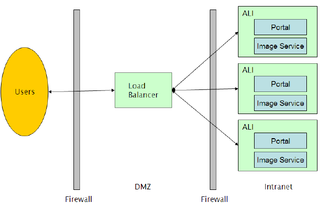
The AquaLogic Interaction Portal can be used with any load balancing system that supports sticky IPs, including Cisco LocalDirector, F5 Big-IP, and Windows NLB, as well as the Apache Web server. BEA does not advocate any specific load balancer.
Session states are maintained by the portal Web servers themselves. If a portal server is taken out of the server farm, user sessions on that server are lost and users will need to log back into the portal.
It is possible for the portal to become unresponsive while the portal Web server is still operational. In this case, the load balancer will assume that the portal is still alive. The load balancer should perform content verification to ensure that the portal is actually available.
The load balancer should send requests to the host with the most available resources instead of performing round-robin distribution of requests. Users use the portal component in different ways, and some users will tax the portal server more heavily than others.
For maximum fault tolerance, load balancers should be clustered.
Another potential load balancing topology is illustrated in Figure 4-2.
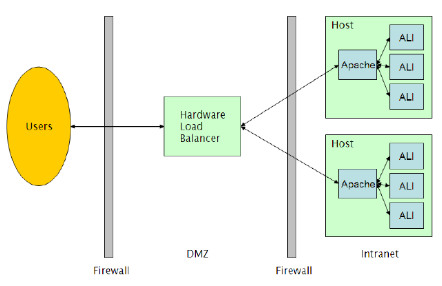
In this example, multiple instances of AquaLogic Interaction are running on a single host, with each portal server listening to a different port. On each host, an instance of Apache balances the load between the instances of AquaLogic Interaction. There are multiple hosts running this configuration, and these hosts are load-balanced by a hardware load balancer in the DMZ. Sticky IPs must be maintained throughout.
On hardware that supports a large number of users, this configuration minimizes the number of user sessions lost in the event of a portal failure.
The Image Service serves static content and does not require sticky IPs. Any number of Image Services can be load balanced.
The document repository service can be load balanced using IP load balancing. This provides partial failover; however, all document repository hosts must share a single, writable file system backing store.
The backing store cannot be load balanced, but failover can be achieved by using a shared local disk with MSCS for failover or a network share implemented with NAS or MSCS.
The Automation Service requires no additional technology for load balancing or failover. Install multiple Automation Services in the AquaLogic Interaction system and designate jobs to run on any set of available servers.
If a server fails mid-job, the job will not complete on another server; however, if the job is scheduled to run periodically, another Automation Service will pick up and run the job.
Search performance can be improved by installing multiple Search instances. Dedicate one instance for indexing jobs and the remaining instances for queries. The indexing instance cannot be load balanced and does not support failover.
There are three levels of load capacity:
The following sections describe how to load balance AquaLogic User Interaction Activity Services.
The following AquaLogic User Interaction products should not be load balanced:
The AquaLogic Interaction portal component provides the Parallel Portal Engine Load Balancer (PPE-LB) to facilitate load balancing and failover services to Activity Services and other portlet Web service providers utilizing HTTP messaging. This eliminates the need for third-party load balancers for middle-tier messaging.
To configure AquaLogic User Interaction Collaboration for clustering, see Clustering AquaLogic Interaction Collaboration.
| Caution: | Not all portlets can be load balanced. If the portlet caches data in memory with the assumption that the underlying database will not be modified, load balancing will cause issues. Consult the portlet documentation or portlet developer to determine if specific portlets can be load balanced. |
The PPE-LB is configured by editing DNS so that one server name (the cluster name) resolves to each IP address in the cluster. Each remote server in the cluster must have a unique IP address and must have the same software installed.
Use nslookup from the portal server to verify that the cluster name resolves to all intended remote server addresses.
| Caution: | Editing the hosts file on a Windows host is not equivalent to configuring DNS. Windows caches and returns only the first IP address instead of returning all IP addresses associated with the cluster. |
| Note: | If the DNS server cannot be configured, contact BEA Customer Support for Windows registry settings that can provide equivalent functionality. |
When using SSL between the AquaLogic Interaction Portal and the remote servers, create a single SSL certifiate by name and add it to each machine in the remote server cluster.
The PPE is implemented with the OpenHTTP standard. OpenHTTP settings are configured in the ALI portal component by editing <PT_HOME>/settings/common/serverconfig.xml.
The following settings are configurable:
Collaboration supports clustering to provide load balancing and fail over. In clustering mode, multiple instances of Collaboration communicate with each other to maintain a single, consistent logical image.
The portal provides load balancing through mapping one domain name to multiple IP addresses. A single domain name that contains the IP addresses of each Collaboration server to be clustered must be provided. Use this name as the portlet remote server name.
You configure Collaboration by editing two files, config.xml and cluster.xml. The files are located in <PT_HOME>/ptcollab/<ver>/settings/config
To enable clustering, perform the following steps on each Collaboration server to be clustered:
By default, Collaboration uses UDP multicasting for communicating between servers. This is the most efficient option and is appropriate for most deployments. In environments where UDP multicasting is not allowed, configure Collaboration to use UDP unicasting.
To configure Collaboration to use UDP unicasting, perform the following steps on each Collaboration server to be clustered:
<coordinator-host>machine.name</coordinator-host>
<coordinator-port>9990</coordinator-port>
| Note: | The port number can be any free port number. |
<profiles profile=’lan-multicast-cluster’><profiles profile=’lan-cluster’>Another optional configuration is to use the wan-cluster profile. The wan-cluster profile uses TCP to communicate directly with specific Collaboration instances.
To enable wan-cluster, perform the following steps on each Collaboration server to be clustered:
<hosts> node. For example, if there are three Collaboration instances, collab01, collab02, and collab03, edit the collab01 cluster.xml to include the other two instances:<hosts>collab02[$port],collab03[$port]</hosts>| Note: | The $port string will be automatically replaced with the <port> setting already configured in cluster.xml. |
<profiles profile=’lan-multicast-cluster’><profiles profile=’wan-cluster’>


|