Specifying Business Service Contracts

The following topics are covered in this chapter:

Overview

The Process Design Assistant is a tool that assists you in creating contracts between applications, then forming them into process flows. This chapter provides instructions for the Business Interface Window of the Process Design Assistant. The Business Interface Window assists you in specifying contracts.

How It Works

The Process Design Assistant is an eLink client/server application. Contracts are specified in the Business Interface Window, then formed into process flows in the Business Process Window. You can also import existing FML definitions (to be used as the basis for contracts) and load interfaces from text files. See Appendix A, "Interface File (*.IFCE) Reference," for more information.

The Process Design Assistant supports the description of any eLink service that uses FML32 buffer types.

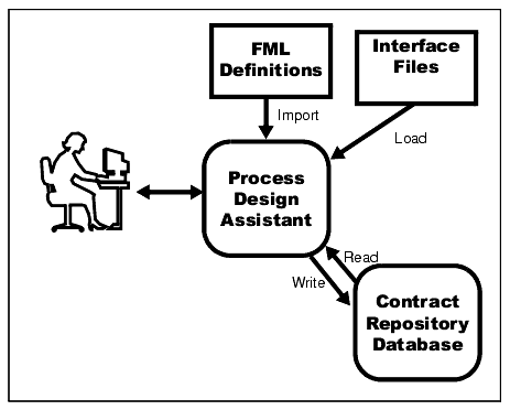
Figure 3-1 shows the workflow using the Contract Repository database. The Process Design Assistant (Business Interface Window) and other key components are described in the next section.

Figure 3-1 Workflow for Specifying Contracts

Key Components

The Process Design Assistant consists of the following components:

Business Interface Window

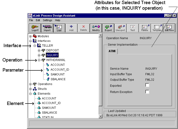
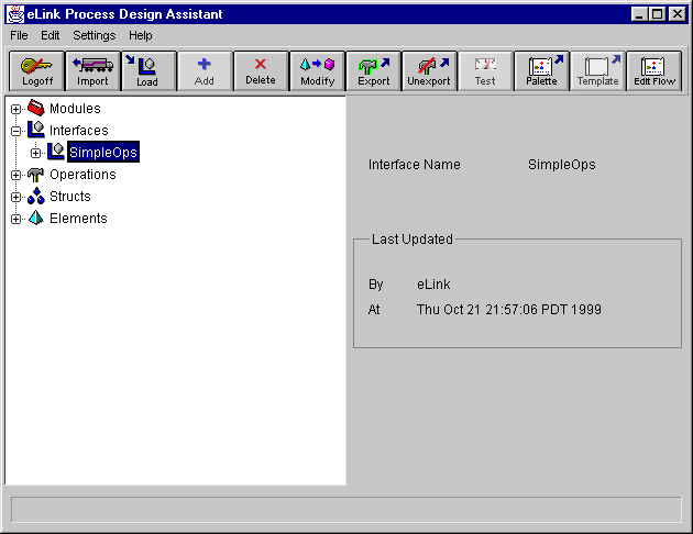
The Business Interface Window shows a tree view of the contracts and their components. When you select an item in the tree, its properties are displayed in the right-hand panel.

Before you can view the tree in the Process Design Assistant, you need to log on. To do this, select File—>Logon from the menu bar or click on the Logon toolbar button.

Accessing Contract Repository Objects

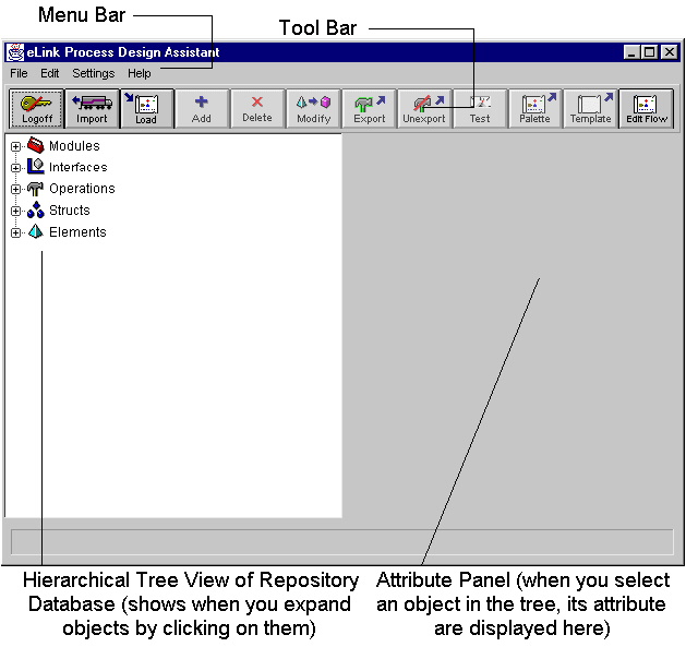
The Process Design Assistant Business Interface Window consists of the menu bar, toolbar and an attribute display. After logon, the root nodes for each Contract Repository object are shown. Figure 3-2 shows the root nodes for each type of object in the Contract Repository tree that display in the left portion of the window.

Figure 3-2 Main Tree Structure

Contract Repository Tree View

As shown in Figure 3-2, there are multiple roots in the tree, one root for each kind of object.

From the tree view, you can create elements, structs, operations, and interfaces.

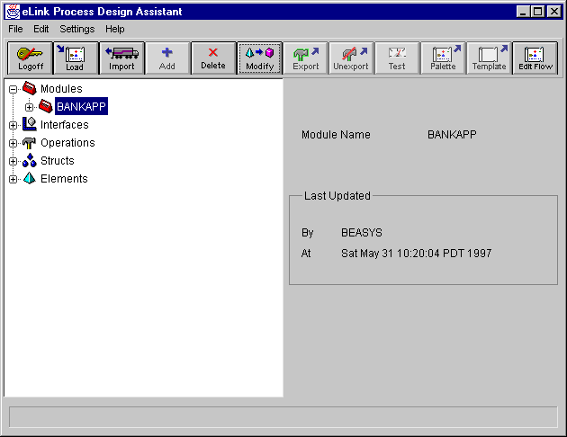
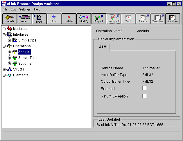
As an example, Figure 3-3 shows the BANKAPP module expanded. Table 3-1 describes each type of object available in the tree in full detail.

Figure 3-3 Module Tree Hierarchy

Table 3-1 Tree Objects

Object Icon Description

Module

A module is a group of one or more interfaces. In eLink, this object type is used only to group and organize interfaces.

Interface

Interfaces are a group of one or more operations. Each interface may be part of one or more modules.

Operation

Operations are implemented as ATMI services. Each operation may be part of one or more interfaces.

When an operation has been exported it shows in a green light.

Parameter

When elements are used in operations, they become parameters or arguments to the operation. Parameters contain additional information (beyond that in the corresponding element), such as passing mode, exception mode, etc.

A parameter is based on a single primary data type (e.g., short, float, char) or a struct.

The parameter attributes available are:

Struct

A struct is a group of previously defined elements. To use a struct as a parameter, define it as an element. Structs cannot be nested.

Element

An element is based on a single primary data type (e.g., short, float, char) or a struct. An element can be used by itself as a parameter to one or more operations, as well as being a part of one or more struct types.

Refreshing the Contract Repository Tree View

During development time, the Contract Repository database may be frequently updated as objects are added, imported, deleted, or modified (by you or other eLink Process Design Assistant users). You must refresh the Process Design Assistant in order to see any changes made after you log on (that is, during a session).

To refresh the Contract Repository, choose File—>Refresh from the menu bar. This updates your view of the Contract Repository database. Note that if the object tree was expanded before you refreshed, it will re-display showing only the initial root nodes. When you re-expand the tree, you will see the updated version.

Toolbar Buttons

The Process Design Assistant Business Interface Window displays a series of icons, or toolbar buttons, under the menu bar used to quickly access frequently used options. Table 3-2 describes the toolbar buttons.

Table 3-2 Toolbar Buttons

Button Label Function

Logon

Logs on to the Process Design Assistant Business Interface Window.

Logoff

Logs off the Process Design Assistant Business Interface Window.

Import FML

Imports FML files.

Load

Loads previously defined operations.

Add

Adds a module, interface, operation, struct, or element.

Delete

Deletes a module, interface, operation, struct, or element.

Modify

Modifies a module, interface, operation, parameter, struct, or element.

Export

Makes the operation available for testing and other purposes.

Unexport

Makes the operation unavailable for testing and other purposes.

Test

Tests the operation.

Palette

Generates a Palette.

Template

Generates a Template.

Edit Flow

Opens the Business Process Window. The Business Process Window is where you can design and edit a business process flow.

Keyboard & Menu Shortcuts

The following table shows the keyboard and menu shortcuts available on the Process Design Assistant.

Action Keyboard Shortcut Menu or Tab Path

Log on to the Process Design Assistant Business Interface Window.

Ctrl L

File—>Logon

Import an FML file into the Contract Repository database.

Ctrl I

File—>Import FML

Loads an interface from a text file called an interface file. For more information on interface files, see Appendix A, "Interface File (*.IFCE) Reference."

File—>Load

Refresh the Process Design Assistant object tree from the Contract Repository database.

Ctrl R

File—>Refresh

Log off the Process Design Assistant Business Interface Window.

Ctrl L

File—>Logoff

Exit the Process Design Assistant Business Interface Window.

None

File—>Exit

Add a module, interface, element, or structure to the selected root tree of kind of object you want to add.

Ctrl Insert

Edit—>Add

Delete the selected object.

Ctrl Delete

Edit—>Delete

Modify the selected object.

Ctrl M

Edit—>Modify

Export the selected object.

Ctrl E

Edit—>Export

Unexport the selected object.

Ctrl E

Edit—>Unexport

Test the selected operation for run-time functionality.

Ctrl T

Edit—>Test

Generates Palette from the selected interface.

Edit—>Generate Palette

Generates Template from the selected operation.

Edit—>Generate Template

Opens the Business Process Window which allows you to edit process flows.

Edit—>Edit Flow

Set default logon values.

Ctrl U

Settings—>Logon

Bring up the online help

F1

Help—>Online Help

Pop-up Menus for Tree Objects. In addition to the menus and toolbar buttons, you can get a pop-up menu of actions for a selected tree object. To do this, select an item in the tree on the Business Interface Window and click the right mouse button to display the actions. Highlight an action on the menu and click the right mouse button again to select it.

Usage

The Process Design Assistant is a tool that assists eLink users in specifying business processes.

This section explains how to work with the Repository Database using the Process Design Assistant.

The following topics are covered:

Logging on and Getting Started

Before starting the Process Design Assistant, make sure that you have installed all necessary software. For details on system requirements, supported platforms, and Process Design Assistant software installation, refer to the BEA eLink Business Process Option Operations & Maintenance Guide included with your CD-ROM.

Starting the Process Design Assistant

To start the Process Design Assistant:

  1. Select the BEA eLink folder icon from your directory tree.

  2. Select the eLink Process Design Assistant icon from the BEA eLink folder. The opening window in Figure 3-4 displays. (If you would like to create a Windows shortcut, see Help for your version of Windows.)

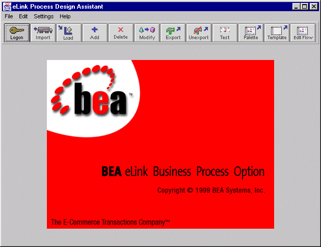
    The BEA eLink Business Process Option opening window (shown in Figure 3-4) appears.

    Figure 3-4 Process Design Assistant at Start Up

Logging On to the Process Design Assistant

Before logging on for the first time, you must set certain logon defaults as this information is not provided by the logon dialog. If you don't set these options, you will be unable to log on to the Process Design Assistant.

Setting Logon Option Defaults

Warning: If the JSL and WSL Port numbers are reversed in error, the server may lock up so check with your System Administrator to make sure that you have the correct port numbers to enter in the Logon Settings Window.

You must set your logon default settings before logging on to the Process Design Assistant.

Note: Setting the logon option defaults need only be done when a new eLink Business Process Option user logs on to the Process Design Assistant for the first time, or should the host access information change.

The first three fields in the Logon settings window must be set up to provide host information for logons. Optionally, the user name may be set as well.

Figure 3-5 Logon Settings Window

Setting the Logon Default Instructions

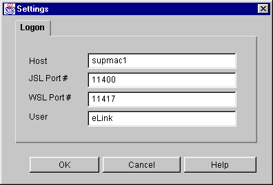
To set the logon default:

  1. Choose Settings —> Logon from the menu bar.

  2. The Settings window in Figure 3-5 displays.

  3. Type the values for Host, JSL Port #, WSL Port #, and User (30-character limit). The Port # fields must be integers. If you do not know this information, ask your System Administrator.

  4. To set the values, click OK. Click Cancel to return to the previous window.

Logging On

Logon Instructions

After starting the Process Design Assistant and setting the logon defaults (required), follow the directions to log on:

  1. Choose File —> Logon from the menu bar

    Or

    Click on the Logon toolbar button.

  2. The Logon window shown in Figure 3-6 displays with text entry fields. Complete these fields to establish a connection with the machine offering the Contract Repository services.

    Figure 3-6 Logon Window
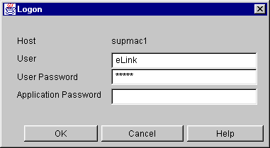
  3. Type the password in the Password field, if required by your server configuration.

  4. Type the application password (8-character limit) in the Application Password field if required by your server configuration.

  5. Click OK.

    Note: The access information for the host displayed in the Logon window must be set up as defaults in the Settings window. See Setting the Logon Default Instructions.

Importing FML Files

The FML file import is a process that imports existing FML files into the Contract Repository. These FML files are maintained by your system administrator.

Note: FML files describing the FML fields that you will be using in eLink (as elements) must be imported before those fields can be used in operations. However, you should import an FML file describing particular FML field definitions only once to avoid overwriting subsequent changes to the operational parameters (elements).

You can import additional new files into the Contract Repository on an ongoing basis as the need for new interfaces arises. If you are unsure as to whether or not a particular FML field definition has been imported, check the properties of the corresponding element by highlighting it in the repository tree. Its properties will appear on the right side of the Business Interface Window. If an element has a non-zero FML field number, its field definition has been imported.

Note: For information on the creation of the FML files, refer to the BEA TUXEDO Programmer's Guide.

When you import FML fields, they are imported as elements. During the import, duplicate entries are updated in the Contract Repository using the new information provided in the import file. The Occurrence default is "1."

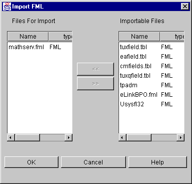
To import FML files, use the Import FML file window (shown in Figure 3-8.) The window has two display areas: Importable Files and Files for Import. The Importable Files display area contains existing FML files that currently reside on your server.

You can select one or more of the files by using the arrow keys to move the files between the display areas. If you move a file to the Files for Import display area, and then decide you do not want to import it, use the arrow keys to move it back to the Importable Files display listing.

Figure 3-7 shows how the import process works. The FML files are imported into the Contract Repository database. If you want to see the objects that you have just imported, you must refresh the tree structure of your GUI by selecting File —> Refresh from the menu bar after the import.

Figure 3-7 FML Import Procedure

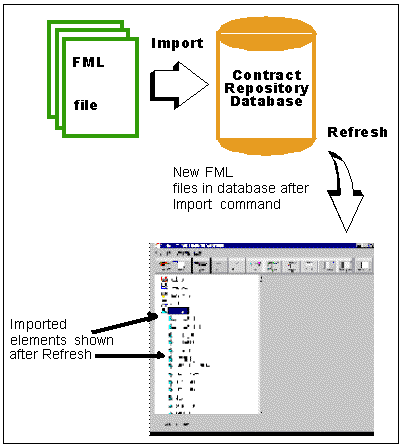
Figure 3-8 FML File Import Window

FML Import Instructions

To use the FML import:

  1. Choose File —> Import FML32 from the menu bar

    Or

    Click on the Import toolbar button.

  2. A window listing the importable FML files displays.

  3. Select the files to import. Use the << or >> buttons to move the files between the display areas.

    Click OK to begin the import process. You can track the status of the import by referring to the messages displayed in the lower left-hand corner of the interface. (Or click Cancel if you decide not to import at this time.)

  4. If the import has not started and you wish to discontinue this process, press Cancel to return to the previous window.

    Note: You cannot cancel an import once it has started. If you inadvertently start the import, wait until it has completed the import cycle. If the import stops due to an error, you are notified by the Alert dialog box. For more information on the Alert window, refer to the Troubleshooting section in this chapter.

  5. When the import is finished the message in the dialog box prompts you to answer, "Do you want to refresh now?" To refresh, click OK.

    If you want to check for any problems encountered during the import, select View Log to view the import activity log before refreshing the GUI.

If you imported a file that contained elements that you do not need, you can delete them. Refer to Deleting Objects From the Repository section in this chapter for information regarding object dependencies. Objects that are dependent on other objects cannot be deleted.

Loading Externally Described Interfaces

As an alternative to interactively defining operations, then grouping them into interfaces, you may wish to load text files describing these operations.

Instructions for Loading Externally Described Interfaces

To load interfaces:

  1. Choose File —> Load Interface from the menu bar.

    Or

    Click on the Load toolbar button.

  2. The Load Interface file selection window displays.

  3. Select the interface file that you want to load into the Process Design Assistant, then click OK.

    A log box will appear indicating the load actions.

  4. When the load completes click to check the Refresh Repository checkbox, then click the OK button.

    The newly loaded interfaces will appear in the Contract Repository tree on the left side of the Business Interface Window.

Creating New Objects

You can create new objects by using the Add option from the Edit menu.

When you populate the Contract Repository, we suggest that you construct your objects from the "bottom up." Create your elements first, then structs, operations, interfaces, and finally, modules. Elements are self-contained, but each of the other objects depend on the object prior to it in the Contract Repository tree (e.g., structs depend on elements).

Follow the instructions in the sections for:

Format Rules for Repository Objects

All object names that you input must conform to the format rules of C language identifiers. Each identifier must start with an alphabetic character or an underscore (e.g., fixed_occurrence). Each identifier can include alphabetic characters, underscores, and numeric characters.

Adding Elements

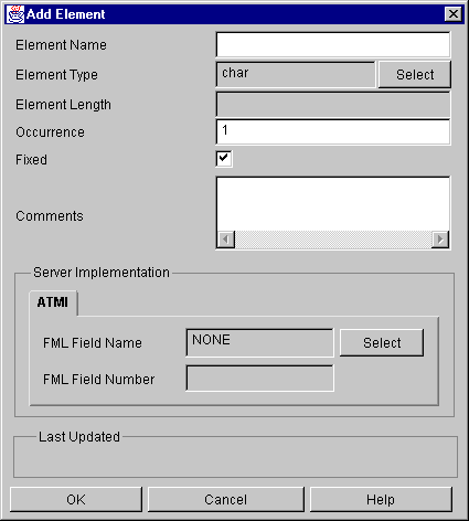
You create new elements by using the Add Element window shown in Figure 3-9.

Figure 3-9 Add Element Window

Table 3-3 Add Element

Field Description

Element Name

Identifies the name of the new element. You must enter the name of the element you wish to create. This field cannot be left blank or contain spaces. The name must not exceed 32 characters.

Element Type

Indicates the element type; either a primary element type (char, string, short, long, float, double, carray) or a struct type. If an element is a member of a struct, you cannot select an element type that is a struct.

To select an element type, click on the Select button next to the Element Type field. (For more information, see Selecting an Element Type.)

Element Length

Enabled when an element type is string or carray. You cannot edit this field for other types.

Occurrence

The number of occurrences of this element. If 0, this indicates an unlimited number of occurrences for the element. If the element is an instance of a struct type, you must indicate "1" for the occurrence and it cannot be edited. The occurrence must not exceed 9 characters. The occurrence number determines the number of data entry fields in the Test Operations dialog box. This is the only effect of this attribute.

Fixed

If the element type is struct type, you must indicate its occurrence as "1," and it must be fixed (if you selected the checkbox).

For all other element types, if the occurrence is "0," it must not be fixed (if you did not select the checkbox). If the occurrence is "1," it must be fixed.

Comments

Allows entry of one line of comment text, without line breaks. You cannot include a colon (:) in the comments.

FML Field Name

Shows the FML field name. To select the FML field name, click on the Select button next to the field. For more information, see Selecting an FML Field Name.

FML Field Number

Shows the FML field number for this FML field.

Last Updated

Displays the date and time of the most recent update and the name of the person who made the update. This area is empty until the element is created.

OK

Saves your addition.

Cancel

Returns to the previous window.

Help

Accesses online help.

Adding Elements Instructions

To add an element:

  1. Select Elements root in the main directory tree.

  2. Choose Edit —> Add from the menu bar

    Or

    Click on the Add toolbar button.

  3. The Add Element window displays.

  4. Complete the text entry fields and click OK to save the new element. Press Cancel to return to the previous window.

Selecting an Element Type

To select an element type from the Adding Elements window:

  1. On the Add Element or Modify Element window, click Select next to the Element Type field.

    This brings up the Select Element Type window as shown in Figure 3-10.

    Figure 3-10 Select Element Type Window

  2. Use the scroll bar to view the available element types.

  3. Select an element type and click OK to save your choice and return to the Add Element or Modify Element window. (Or click Cancel to close the window without saving your changes.)

Selecting an FML Field Name

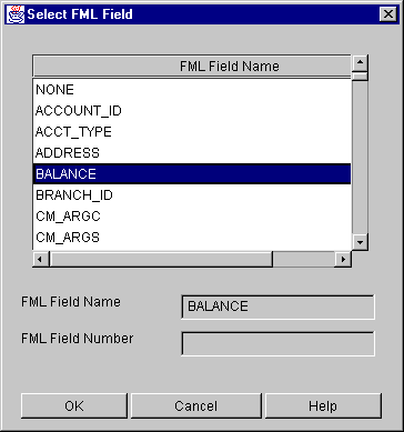
To select an FML field name:

  1. On the Add Element or Modify Element window, click Select next to the FML Field Name field.

    This brings up the Select FML Field window as shown in Figure 3-11.

    Figure 3-11 Select FML Field Window

  2. Review the list of available FML Field Names and select a field name from the list.

  3. Click OK to save your changes. (Or click Cancel to close the window without saving your changes.)

Adding Structs

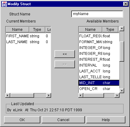
Structs (also referred to as "structures") comprise a group of available element members. A struct cannot be nested within a struct. Each member has a name, type, and length information. Use the << or >> keys to move members between current and available status. When a member name is moved, all of the information accompanying the member is moved. See Format Rules for Repository Objects for information about object naming conventions.

Figure 3-12 Add Struct Window
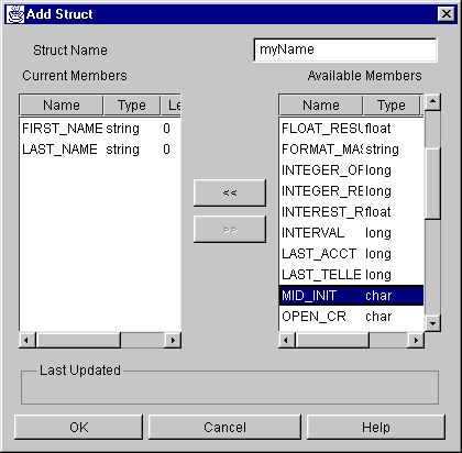
Table 3-4 Add Struct

Field Description

Struct Name

Identifies the name of the struct. You must enter the name of the struct you wish to create that is unique and does not exceed more than 31 characters.

Current Members

Lists the current member names for the struct. The display area is blank for all new structs.

Available Members

Lists available member names for the struct.

Arrow keys (<< or >>)

Moves selected item between Current Members and Available Members.

Last Updated

Displays the date and time of the most recent update and the name of the person who made the update. This area is empty until the struct is created.

OK

Saves your addition.

Cancel

Returns to the previous window.

Help

Accesses online help.

Adding Structs Instructions

To add a struct:

  1. Select Structs in the main directory tree.

  2. Choose Edit —> Add from the menu bar

    Or

    Click on the Add toolbar button.

  3. The Add Struct window in Figure 3-12 displays.

  4. Complete the text entry fields and click OK to save the new struct. Press Cancel to return to the previous window.

Adding Operations

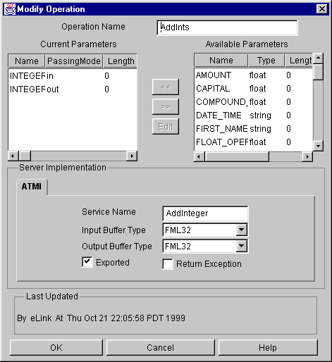
To add operations, the list of available parameters (based on previously defined elements) is displayed on the right scrollable list. Type the operation name in the text entry field, select the parameters, and enter the ATMI server implementation information. See Format Rules for Repository Objects for information about object naming conventions.

The Edit button is used to change a parameter's passing mode and mandatory attributes after it has been moved from the available list. See Modifying Parameters for additional information. The default fields are shown below.

Field Default

Passing Mode

in

Mandatory

Yes

Display Name

Parameter name

Figure 3-13 Add Operation Window

Table 3-5 Add Operation

Field Description

Operation Name

Identifies the name of the operation. You must enter the name of the operation you wish to create. This field cannot be left blank or contain spaces. The name must not exceed 32 characters.

Current Parameters

Lists the current parameter names for the operation.

If the Current Parameters list contains a parameter that is a struct type, it is not allowed to have another parameter that is a member of the struct type parameter. In addition, if the Current Parameters list contains a basic parameter, it is not allowed to have another struct type parameter that contains a member of the basic parameter.

Available Parameters

Lists available parameter names for the operation.

Arrow keys (<< or >>)

Moves selected item between Current Parameters and Available Parameters.

Edit

Enables editing of a selected current parameter. This option is disabled if you have not selected a current parameter.

When you select a "current parameter" and click Edit, you get the Edit Parameter window, which functions exactly the same as the Modify Parameter window.

For information about how to edit the parameter, see Modifying Parameters.

ATMI Service Name

Identifies the ATMI service that implements the operation. It is the name used within the eLink environment to connect to business services either offered by or called by eLink adapters. The ATMI Service Name must not be left blank and must obey the ATMI service naming conventions.

Input Buffer Type and Output Buffer Type

FML32 — a type in which each field carries its own definition.

NONE — placeholder indicating that no input or output is required.

Exported

Exported operations are made available for testing, generating palettes and templates, and web apps for use in run time. Select the checkbox to export the operation. If you do not select the checkbox, the operation remains unexported.

Return Exception

Enabled if exceptions are returned.

Last Updated

Displays the date and time of the most recent update and the name of the person who made the update. This area is empty until the operation is created.

OK

Saves addition.

Cancel

Returns to the previous window.

Help

Accesses online help.

Adding Operations Instructions

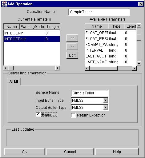
To add an operation:

  1. Select Operation in the main directory tree.

  2. Choose Edit —> Add from the menu bar

    Or

    Click on the Add toolbar button.

  3. The Add Operation window in Figure 3-13 displays.

  4. Complete the text entry fields and click OK to save the new operation. Press Cancel to return to the previous window.

Adding Interfaces

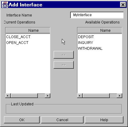
You can create an interface by accessing the Add Interface window. The available operations are displayed on the right and the current operations are displayed on the left. Use the arrow buttons to move operations in or out of the interfaces. See Format Rules for Repository Objects for information about object naming conventions.

Figure 3-14 Add Interface Window

Table 3-6 Add Interface

Field Description

Interface Name

Identifies the name of the interface. You must enter the name of the interface you wish to create. This field cannot be left blank or contain spaces. The name must not exceed 32 characters.

Current Operations

Lists the current operation names for the interface. The display area is blank for all new operations. The Current Operations list can remain empty.

Available Operations

Lists available operation names for the interface.

Arrow keys (<< or >>)

Moves selected item between Current Operations and Available Operations.

Last Updated

Displays the date and time of the most recent update and the name of the person who made the update. This area is empty until the interface is created.

OK

Saves your addition.

Cancel

Returns to the previous window.

Help

Accesses online help.

Adding Interface Instructions

To add an interface:

  1. Select the root of the interface tree.

  2. Choose Edit —>Add from the menu bar

    Or

    Click on the Add toolbar button.

  3. The Add Interface window in Figure 3-14 displays.

  4. Complete the text entry fields and click OK to save the new interface. Press Cancel to return to the previous window.

Adding Modules

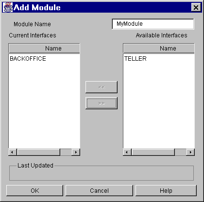
Figure 3-15 shows the Add Module window. To create a module, select the root of the module tree, choose Edit—>Add from the menu bar to display the Add Module dialog box, and type the name in the Module Name text entry field. Select the module's current interfaces by moving items from the Available Interfaces display area to the Current Interfaces display area. See Format Rules for Repository Objects for information about object naming conventions.

Figure 3-15 Add Module Window

Table 3-7 Add Module

Field Description

Module Name

Identifies the name of the module. You must enter the name of the module you wish to create. This field cannot be left blank or contain spaces. The name must not exceed 32 characters.

Current Interfaces

Lists the current interface names for the module. The display area is blank for all new modules. The Current Interfaces list can remain empty.

Available Interfaces

Lists available interface names for the module.

Arrow keys (<< or >>)

Moves selected item between Current Interfaces and Available Interfaces.

Last Updated

Displays the date and time of the most recent update and the name of the person who made the update. This area is empty until you create a module.

OK

Saves your addition.

Cancel

Returns to the previous window.

Help

Accesses online help.

Adding Modules Instructions

To add a module:

  1. Select the root of the Module tree in the main directory tree.

  2. Choose Edit —>Add from the menu bar

    Or

    Click on the Add toolbar button.

  3. The Add Modules window in Figure 3-15 displays.

  4. Complete the text entry fields and click OK to save the new module. Press Cancel to return to the previous window.

Modifying Objects

You can modify objects at any time. You may choose to modify an object to incorporate a name change or any other change to the object. This section describes:

Modifying Elements

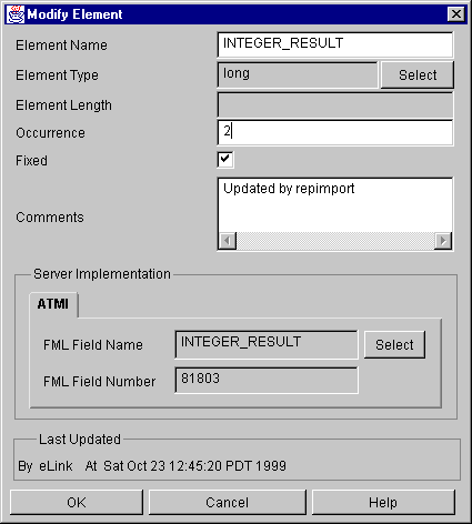
You can modify an element at any time, including when you are creating new modules or after testing an operation. The Modify Element window in Figure 3-17 is used to modify elements. An element may be altered to incorporate occurrences, disable or enable the fixed-field length, add comments, and change server implementation information. See Adding Elements for a description of the element window.

Note: The element length can be altered only if the element type is string or carray.

Figure 3-16 Element Selection Window

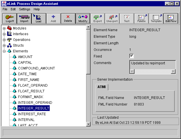
Modifying Elements Instructions

To modify an element:

  1. Select the element to modify.

  2. Choose Edit —> Modify from the menu bar

    Or

    Click on the Modify toolbar button.

  3. The Modify Element window shown in Figure 3-17 displays.

    Figure 3-17 Modify Element Window

  4. Make the changes to the element.

  5. Click OK to activate the changes and close the window.

    (Or click Cancel to close the window without saving your changes.)

Modifying Structs

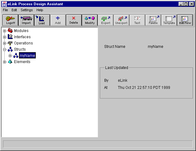
You can modify a struct from the Struct main window shown in Figure 3-18. To modify a struct, the current elements display in the left window and the available elements display in the right window as shown in Figure 3-19. The arrow buttons in the middle can be used to move elements in or out of the struct. See Adding Structs for a description of the struct window.

Figure 3-18 struct Selection Window

Modifying Structs Instructions

To modify a struct:

  1. Select the struct to modify.

  2. Choose Edit —> Modify from the menu bar

    Or

    Click on the Modify toolbar button.

  3. The Modify Struct window shown in Figure 3-19 displays.

    Figure 3-19 Modify Struct Window

  4. Type the new struct name or move the members.

  5. Click OK to activate the changes and close the window.

    (Or click Cancel to close the window without saving your changes.)

Modifying Parameters

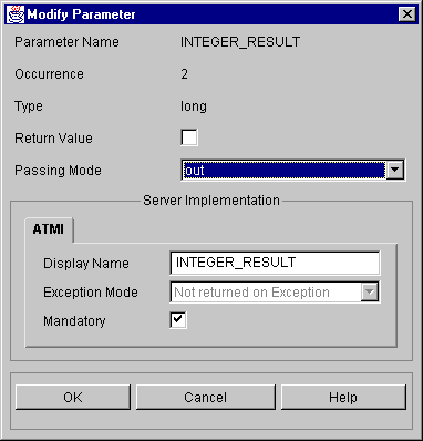
You can modify a parameter from the Business Interface Window (by selecting it in the tree and clicking Modify as shown in Figure 3-20).

Note: You can also modify a parameter as a part of adding or modifying operations. When you select a "current parameter" in the Add Operation or Modify Operation window and click Edit, you get the Edit Parameter window, which functions in the exact same way as the Modify Parameter window. (See Adding Operations or Modifying Parameters.)

For complete instructions see Modifying Parameter Instructions. (The Modify Parameter window is shown in Figure 3-21.)

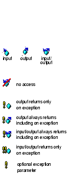
A parameter may be modified to enable or disable the return value, or change the passing mode by selecting IN, IN/OUT, OUT, or NO ACCESS. In addition, the ATMI server information can be modified to reflect a display name change, a change in the exception mode return status, and enable or disable the mandatory status.

Figure 3-20 Parameter Selection Window

Modifying Parameter Instructions

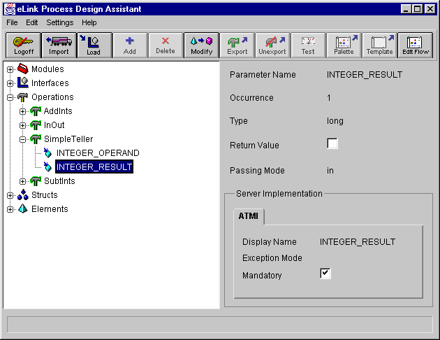
To modify a parameter from the Business Interface Window:

  1. Select the parameter to modify.

  2. Choose Edit —> Modify from the menu bar

    Or

    Click on the Modify toolbar button.

    This brings up the Modify Parameter window shown in Figure 3-21.

    Figure 3-21 Modify Parameter Window

  3. Fill in the fields as described in the following table.

    Table 3-8 Modifying Parameters

    Field Description

    Parameter Name

    Indicates the same name of the element name used to create the parameter. To modify the parameter name, modify the element name first.

    Occurrence

    Indicates the number of occurrences of this element. If 0, the element can have an unlimited number of occurrences. The only way to modify the parameter occurrence is to modify the element occurrence. The occurrence number determines the number of data entry fields in the Test Operations dialog box. This is the only effect of this attribute.

    Type

    Type of element; either a primary element type FML (char, string, short, long, float, double, carray) or VIEW (int, short, long, char, float double, string carray) or a struct type. To modify the parameter type, modify the element type first.

    Return Value

    Select the checkbox if the element is used as a return value. Only one parameter from the Current Parameters list of an operation can have a return value.

    Passing Mode

    Indicate the direction of movement for the data:

    in
    out
    in/out
    noaccess

    You can have only one parameter from the Current Parameters list for an operation that is listed as the return value. The passing mode of this parameter must be "out."

    Display Name

    Type a 32 character parameter name. This name must be unique within one operation.

    Exception Mode

    For out or in/out parameters, this mode indicates how the parameter is returned on exceptions. Enabled only for out and in/out passing modes when return exception is enabled for the operation.

    Mandatory

    Indicates if the parameter is required or optional. An occurrence of "1" is mandatory (if you selected the checkbox). An occurrence of "0" is not mandatory (if you did not select the checkbox).

  4. Make changes to the Return Value, Passing Mode, or Display Name.

  5. Click OK to activate the changes and close the window. When the changes have been made to the module, the update status changes to reflect the most recent modification.

    (Or click Cancel to close the window without saving your changes.)

Modifying Operations

You can modify an operation by selecting an operation from the repository tree as shown in Figure 3-22. See Adding Operations for a description of the operation window.

Note: You can modify the components of an exported operation. You do not have to unexport the operation in order to modify its components. If you modify an exported operation, it does not automatically change to unexported status. A modified exported operation remains exported until you unexport it with the unexport toolbar button or menu option.

Figure 3-22 Operation Selection Window

Modifying Operations Instructions

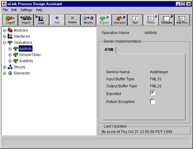
To modify an operation:

  1. Select the operation to modify.

  2. Choose Edit —> Modify from the menu bar

    Or

    Click on the Modify toolbar button.

  3. The Modify Operation window in Figure 3-23 displays.

    Figure 3-23 Modify Operation Windows

  4. Type the new operation name, move the parameters, edit parameters, or modify the Server Implementation details.

  5. Click OK to activate the changes and close the window.

    (Or click Cancel to close the window without saving your changes.)

Modifying Interfaces

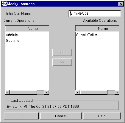
You can make changes to an interface by selecting the interface from the directory tree shown in Figure 3-24. See Adding Operations for a description of the interface window.

Figure 3-24 Interface Selection Window

Modifying Interfaces Instructions

To modify an interface:

  1. Select the interface to modify.

  2. Choose Edit —> Modify from the menu bar

    Or

    Click on the Modify toolbar button.

  3. The Modify Interface window in Figure 3-25 displays.

    Figure 3-25 Modify Interface Window

  4. Use the << or >> keys to move the operations.

  5. Click OK to make the changes. When the changes have been made to the module, the update status changes to reflect the most recent modification.

    (Or click Cancel to close the window without saving your changes.)

Modifying Modules

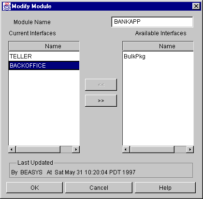
Modify a module by selecting the object from the directory tree shown in Figure 3-26. See Adding Operations for a description of the module window.

Figure 3-26 Modules Selection Window

Modifying Modules Instructions

To modify a module:

  1. Select the module to modify.

  2. Choose Edit —> Modify from the menu bar

    Or

    Click on the Modify toolbar button.

  3. The Modify Module window in Figure 3-27 displays.

    Figure 3-27 Modify Module Window

  4. Use << or >> keys to move the interfaces between the Current Interfaces and Available Interfaces display lists.

  5. Click OK to make the changes. When the changes have been made to the module, the update status changes to reflect the most recent modification.

    (Or click Cancel to close the window without saving your changes.)

Deleting Objects From the Repository

This section details the necessary steps to delete an object. You can delete a module, interface, operation, parameter, struct, or element. After deletion, the object is gone. There is no recycle bin in the Contract Repository, so if you inadvertently delete an object you must create a new one to replace it.

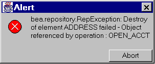
You cannot automatically delete an object that is dependent on (or used by) another object. If you attempt to delete an object that is in use in the Contract Repository, you receive an Alert message. The Alert message shows where the object is being used. When you click OK, the Alert window closes. So, before you close the Alert window, you may want to note where the object is being used. You cannot delete the object until you remove the dependency.

A module is the only object that does not have any dependencies.

Deleting Instructions

To delete an object:

  1. Select the object to be deleted from the Business Interface Window.

  2. Choose Edit —> Delete from the menu bar

    Or

    Click on the Delete toolbar button.

  3. To confirm that you want to delete the object, the dialog box, "Do you really want to delete <name of the object>?" displays.

    Figure 3-28 Delete Module Window

  4. Click OK to delete. Click Cancel to return to the previous window.

  5. If there is a dependency, the Alert window displays. If you still want to delete the object, refer to the Alert window shown in Figure 3-29 for the dependencies.

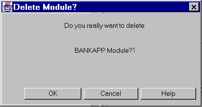
    Figure 3-29 Alert Window with Dependency Information

  6. In this example, the object, ADDRESS element, cannot be deleted because it is referenced by (or is depended upon by) the OPEN_ACCT operation. If you wish to delete the object, you must remove the dependency by modifying the OPEN_ACCT operation. In this case, you would need to remove the ADDRESS element from OPEN_ACCT before proceeding with the delete. If you have to remove a parameter, modify the operation and delete it using the Modify Operation window.

    For additional information, refer to the Modifying Objects section in this chapter.

Exporting or Unexporting an Operation

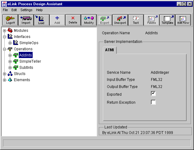
Once you have completed building an operation, you are ready to test it. Before you can test an operation, you must export it. "Export" serves as a flag that makes it available for testing, generating palettes and templates, and web or Windows applications for use in run time.

By default, the operation is always unexported as shown in Figure 3-30.

You have the option to export or unexport all operations within the interface at one time.

You do not have to make all operations available to the client at the same time, even if your interface contains several operations.

Figure 3-30 Window with Unexported Operation

Export Instructions

To export:

  1. Select an interface or operation from the Business Interface Window. If you select an interface, all of the operations in the interface will be exported.

  2. Choose Edit —> Export from the menu bar

    Or

    Click on the Export toolbar button.

  3. The Exported checkbox is checked to indicate that the operation has been exported as shown in Figure 3-31.

    Figure 3-31 Window with Exported Operation

Unexport Instructions

To unexport an operation:

  1. Select an interface or operation from the Business Interface Window. If you select an interface, all operations in the interface will be unexported.

  2. Choose Edit —> Unexport from the menu bar

    Or

    Click on the Unexport toolbar button.

  3. The Exported checkbox is unchecked to indicate that the operation has been unexported as shown in Figure 3-30.

Testing an Operation

You can test an operation and its parameters to ensure that all components are functioning properly before you can use the operation further.

Once an operation is exported you can test it. If the test fails and editing is required to fix the operation, you do not have to unexport the operation prior to editing.

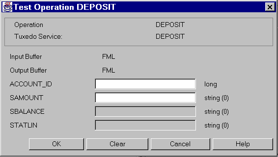
The operation test window allows you to test previously defined operations to verify their function against the service implementation. The window contents are based on the number and type of parameters the operation expects. If an operation has multiple parameters and cannot be viewed on one screen, a scrollbar displays to navigate through the parameters.

Figure 3-32 Test Operation Window

Table 3-9 Test Operation

Field Description

Operation

The name of operation that you selected to be tested.

ATMI Service

The name of the associated ATMI service.

Input Buffer and Output Buffer

Only FML32 buffer types are supported.

FML32 — a type in which each field carries its own definition.

NONE — placeholder indicating that no input or output is required.

Parameter text fields

The parameter information text entry field. The fields that display in the test window are dependent on the operation you are testing. Based on the passing mode, these fields are writable or read-only. Fields are disabled if read-only.

OK

Runs the operation.

Clear

Clears all fields and resets the scrollbar to the top (if a scrollbar is present).

Cancel

Exits the window.

Guidelines for Inputting Data

Test Operation Instructions

To test an operation:

  1. Select the operation to test.

  2. Choose Edit —> Test from the menu bar

    Or

    Click on the Test toolbar button.

  3. Input data in the Operation test window parameter text field.

  4. Click OK. The message, "Test Complete," displays if the test passes. If the test fails, a message displays in the Alert window.

    Follow the instructions below if editing is required to pass the test.

    1. Return to the Business Interface Window and select the operation, parameter, struct or element that requires editing.

    2. Choose Edit—>Modify from the menu bar.

Logging Off and Exiting

Log off the Process Design Assistant before exiting it. The Logoff option is only enabled after logon.

Figure 3-33 Exit Prompt

Logoff/Exit Instructions

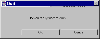
To log off and exit:

  1. To log off the Process Design Assistant, choose File —> Logoff from the menu bar

    Or

    Click on the Logoff toolbar button.

  2. The opening Process Design Assistant window displays.

  3. To exit the Process Design Assistant, choose File—> Exit from the menu bar.

  4. The prompt, "Do you really want to quit?" displays in the dialog box shown in Figure 3-33. Click OK to exit or Cancel to return to the Process Design Assistant opening window.

Troubleshooting

You are "alerted" through an alert window of any error that occurs while running the application. You will receive an alert message if the system is unable to:

The message in Figure 3-34 is an alert about an object dependency.

Figure 3-34 Alert Window

Alert Window Instructions

When the Alert window displays:

  1. Read the message and follow the suggestions for a possible solution.

  2. Click Abort upon completion of reading the message to remove the window.

Process Design Assistant and ATMI Mappings

Table 3-10 Mappings Between Contract Repository and ATMI

Contract Repository ATMI

module

interface

operation

service

structure

Group of FML fields

exception

TPFAIL with return buffer

parameter

FIELD in buffer

parameter (return value)

FIELD in buffer

mandatory occurrence

FIELDs in buffer

maximum occurrence

FIELDs in buffer

element

FIELD definition in FML field table