

|

|
|
|
|
Understanding the SNACRM
This section discusses the following topics:
About the SNACRM
The System Network Architecture Communications Resource Manager (SNACRM) is used with the BEA WebLogic Java Adapter for Mainframe (JAM) to manage communications resources. The SNACRM coordinates the flow of data between Java applications running on a WebLogic Server platform and applications running on a mainframe. The mainframe applications may use the following protocols: Customer Information Control System/Enterprise System Architecture (CICS/ESA), Distributed Program Link (DPL), or Information Management System (IMS). The SNACRM runs as a separate native process providing emulation that allows CICS/ESA, DPL, and IMS protocols to flow into and out of the Java environment.
Version 4.1 of the SNACRM has been enhanced with the following new features:
The SNACRM supports non-transactional Information Management System (IMS) programs using implicit Application Program-to-Program (APPC) support for IMS. Implicit APPC is similar to the CICS/ESA DPL. Any IMS program that sends and receives messages to and from the IMS message queue can be used as either a client or a server without change.
To use the implicit APPC capabilities of IMS, you must modify the APPCM file in the SYS1.PARMLIB Partitioned Data Set (PDS) under OS/390. The configuration parameters in this file associate the Logical Unit (LU) with the IMS scheduler. You must identify the LU representing the application name used by JAM to access the IMS region and the IMS system ID that provides scheduling for inbound requests. Consult with your mainframe support personnel before making changes to the APPCM file.
System Configuration
The SNACRM system may be configured as either a local configuration or a distributed configuration running on Unix, Windows NT, or a mainframe operating system. For a complete list of operating systems, refer to the BEA WebLogic Java Adapter for Mainframe Release Notes. If the SNACRM is not run on a mainframe, it must run on the same platform as the SNA stack. If the gateway is running on a platform other than the one the SNACRM is on, then the SNACRM should already be started and monitoring the address specified in the gateway configuration.
Local Configuration
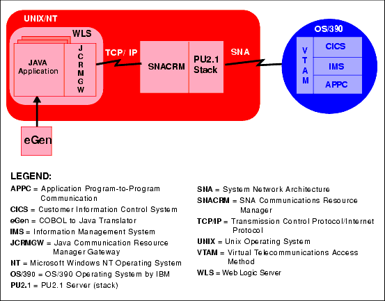
The local configuration, illustrated in Figure 1-1, combines the Java application, JCRMGW, WebLogic Server, and the SNACRM with the stack (PU2.1 server) on the same Unix or Windows NT platform. It employs the IBM proprietary SNA protocol for transactions with the mainframe via the stack.
Figure 1-1 JAM Local Configuration

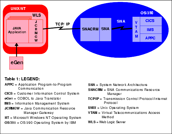
One type of distributed configuration separates the Java applications and JCRMGW from the SNACRM by moving the SNACRM to the IBM OS/390 Mainframe. See Figure 1-2. This configuration eliminates the need for a third-party stack on the Unix or NT machine.
Figure 1-2 JAM Distributed Configuration

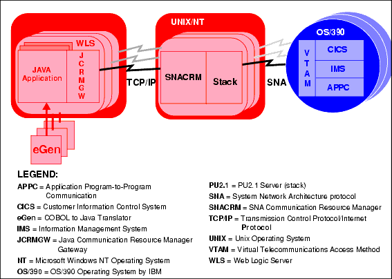
Another type of distributed configuration separates the Java applications and JCRMGW from the SNACRM on different Unix or Windows NT platforms. See Figure 1-3. This configuration employs Transmission Control Protocol/Internet Protocol (TCP/IP) connectivity between the Java applications platform and the SNACRM platforms, as well as the SNA connectivity to the mainframe environment(s). It provides the flexibility to deploy WebLogic Server separately from the SNACRM at installations that require WebLogic Server on a platform other than the one on which the SNA stack is running. Note that this configuration requires a one-to-one relationship between the local JCRMGW and the remote SNACRM.
Figure 1-3 Alternate JAM Distributed Configuration

Remote Host Domain Configuration
A basic understanding of the mainframe configuration requirements provides a context for understanding the SNACRM functions and configuration requirements.
Note: Always consult with your local mainframe system administrator for specific information about your system. Any samples provided illustrate a starting point for configuring your system and do not represent all possibilities. The samples represent one way a mainframe can be configured to work in an Advanced Peer-to-Peer Networking (APPN) Local Area Network (LAN) environment.
You must ensure the CICS/ESA remote domain is prepared to conduct operations with the BEA local domain. This includes:
Establishing the VTAM Configuration
The SNACRM communicates with the gateway. If your JAM system is used in a Virtual Telecommunications Access Method (VTAM) environment, you must ensure the host configuration supports it. Refer to "Sample VTAM Configurations," for some examples based on the requirements for the JAM to be used in a VTAM environment with an Ethernet LAN and an APPN mainframe system.
Configuring the CICS/ESA LU
Before you can connect to the remote stack, the LU (Logical Unit) configuration must be established. This entails creating connection definitions, creating session definitions, and installing resource definitions.
Creating Connections at the Remote Host
If a remote connection definition file is not already in place, you must work with the mainframe support personnel to create one. When placed on the remote host, the definition provides a connection with the local domain. Note the following example of a JAM connection definition file:
DEFINE CONNECTION(BEA)      GROUP(BEACONN)
       DE(JAM EXAMPLE RDO CONNECTION)
       ACCESSMETHOD(VTAM)   PROTOCOL(APPC)
       NETNAME(**VTAM NETWORK NAME OF REMOTE SYSTEM**)
       ATTACHSEC(LOCAL)     AUTOCONNECT(NO)
To install the sample connection definition, put it on the host in a separate group. Use the CEDA INSTALL command.
For example:
CEDA INSTALL GROUP(BEACONN)
Defining the Session at the Remote Host
If a session definition is not already in place, you must work with the mainframe support personnel to create one. When placed on the remote host, the session definition defines the logical links by which the local domain communicates with the remote host. Note the following example of a JAM session definition:
DEFINE SESSION(BEATEST)       GROUP(BEACONN)
       CONNECTION(BEA)
       DE(JAM EXAMPLE RDO SESSION)
       PROTOCOL(APPC)         AUTOCONNECT(YES)
       MODENAME(**MODE**)     MAXIMUM(**SESSNBR**,**WINNER**)
AUTOCONNECT indicates how the activation of the session is negotiated. YES enables the CICS/ESA host to negotiate its own winner sessions when a conversation is allocated.
The MODENAME can be either a CICS/ESA-supplied mode name, such as SMSNA100, or your own defined mode name. If another set of session definitions exist for the BEA connection, this mode name must be unique among all sets defined to the connection. The mode name corresponds to the VTAM LOGMODE name.
The MAXIMUM option defines the total number of sessions in the set and the total number of winner sessions. The total number of winner sessions must include those for the host and the remote stack. The WINNER number plus the remote WINNER number should equal the SESSNBR.
View Connection and Session Status
After you have installed group definitions, you can view the status of connections and sessions using the following CICS/ESA system commands:
CEMT I CONN(BEA)            **view the status of the connection
CEMT I NET(**Netname**)     **View the status of the sessions
CEMT I MODENAME(**MODE**)   **View the status of the mode
Completing Cross-Platform Definitions
Consult with your CICS/ESA remote domain administrator to obtain key parameters in the VTAM definition that must be included in the SNA stack configuration, as well as in other configuration files in the JAM local domain.
VTAM Cross-Platform Definitions
Before installing JAM software, please examine Table 1-1 for a summary of cross-platform definitions. Consult with the VTAM system administrator to obtain the value indicated in the Name column and make the corresponding entries shown in the Needed In column.
.
|
Item |
Name |
Originates In |
Needed In |
|---|---|---|---|
1. |
SNA Network ID and VTAM Host ID |
VTAM configuration |
SunLink SNA Stack Configuration: SNAplus2 or IBM CS/AIX Stack Configuration: Example: |
2. |
Mode Name |
VTAM-MODEENT definition |
CICS Sessions Definition: SunLink SNA Stack Configuration: SNAplus2 Stack Configuration: JCRMGW Configuration: |
3. |
Control Point Name |
VTAM-PU definition |
SunLink SNA Stack Configuration: SNAplus2 Stack Configuration: |
4. |
Local LU Name |
VTAM-LU definition |
CICS CONNECTION definition: SNAplus2 Stack Configuration: JCRMGW Configuration: |
5. |
CICS LU Name |
VTAM-LU definition |
SunLink SNA Stack Configuration: SNAplus2 Stack Configuration: JCRMGW Configuration: |
6. |
Terminal Identifier |
VTAM |
SunLink SNA Stack Configuration: SNAplus2 Stack Configuration: |
7. |
Local Network Device |
UNIX Configuration |
SunLink SNA Stack Configuration: |
8. |
Local MAC Address |
Token ring address of Host |
SunLink SNA Stack Configuration: |
9. |
Remote MAC Address (token ring only) |
Token ring address of local machine |
SunLink SNA Stack Configuration: SNAplus2 Stack Configuration: |
10. |
LAN Speed |
Speed of token ring network |
SunLink SNA Stack Configuration: |
11. |
SDLC parameters (line protocol) |
VTAM-line definition |
SunLink SNA Stack Configuration: |
12. |
Partner Definition (e.g. TUXPART1) |
CICS/ESA |
Mainframe Client Application: |
13. |
Set LU definition so maximum sync-level allowed corresponds to JCRMGW.CFG entry: |
Stacks |
SunLink SNA Stack Configuration: SNAplus2 Stack Configuration: |
14. |
Map all incoming conversations to BEA Connect SNA gateway (make sure TPs have all privileges available, e.g. CNOS, syncpoint if licensed, service conversations, etc.). |
Stacks |
SunLink SNA Stack Configuration: SNAplus2 Stack Configuration: |
15. |
CICS Transaction IDs (e.g. TOUP) |
CICS/ESA |
JCRMGW Configuration: |
Before installing JAM software, please examine Table 1-2 for a summary of OS/390 SNA definitions. Consult with the system administrator to obtain the value indicated in the Name column and make the corresponding entries shown in the Needed In column.
.
|
Item |
Name |
Originates In |
Needed In |
|---|---|---|---|
1. |
Local LU Name |
VTAM-LU definition |
CICS CONNECTION definition: |
2. |
Mode Name |
VTAM-MODEENT definition |
CICS Sessions Definition: |
3. |
CICS LU Name |
VTAM-LU definition |
GWSNAX Configuration: |
4. |
Set LU definition so maximum sync-level allowed corresponds to DMCONFIG file entry |
Stacks |
VTAM Configuration:
|
5. |
CICS Transaction IDs (e.g. TOUP) |
CICS/ESA |
GWSNAX Configuration: |
Microsoft SNA Cross-Platform Definitions
It is important to communicate with the administrator of the CICS/ESA remote domain to obtain key parameters in the VTAM definition that must be included in the Microsoft SNA Server configuration, as well as in other configuration files in the JAM local domain.
Before installing JAM software, please examine the following general procedure for configuring the Microsoft SNA Server. Use the Microsoft SNA Server Manager GUI. Sample values are shown in parenthesis. Consult with the VTAM system administrator to obtain the proper values.
In the Link Service Properties, define DLC 802.2 Link Service Configuration:
In the MVSNT1 Properties, define:
General
Address
System Identification
802.2 DLC
General
Advanced
General
Options
General
Limits
Characteristics
Partners
Compression
Setting SNACRM and Stack Traces
Trace capabilities are provided for the SNACRM process. To initiate stack tracing, you include the -t option for the SNACRM command along with a number to specify the level of tracing. Refer to Trace Options for the SNACRM command in the Command Reference Pages.
The APPC Stack API trace is either enabled or disabled using the -s option of the SNACRM command (refer to General Options for the SNACRM command in the Command Reference Pages). If enabled, it generally shows the parameters and results of all API calls. Depending on the stack being used, other options (such as vendor-specified environment variables) may have to be activated for SNACRM to enable the trace. Consult the vendor publications for instructions on how to set up stack tracing.

|

|

|
|
|
|
Copyright © 2000 BEA Systems, Inc. All rights reserved.
|