

|
This chapter provides the following sections:
Applications can define event cycle specifications (ECSpec) and programming cycle specifications (PCSpec) where the beginning or end of each cycle is triggered by external events. BEA provides an extensible mechanism for connecting sources of external events to the ALE engine.
OPC is a series of standards specifications that define a standard set of objects, interfaces, and methods for use in process control and manufacturing automation applications to facilitate interoperability. (For more information on OPC, see http://www.opcfoundation.org.)
WebLogic RFID Edge Server includes a driver for OPC triggers. An event or programming cycle in the Edge Server can be triggered by polling for a change in an OPC item. The Edge Server communicates with the OPC service using the OPC XML-DA protocol, which is a SOAP interface to an OPC Data Access provider. The OPC XML-DA implementation is provided by a third party.
The general form of the trigger URI is:
opcpoll:itemName=item;http://hostname/location
When an event cycle or programming cycle that uses an OPC trigger is first requested (that is, when the event cycle or programming cycle is invoked using the poll or immediate method or subscribed using subscribe), the Edge Server polls the OPC XML-DA server for the current value of the specified OPC item. Subsequently, each time the value of the OPC item changes, a trigger will be delivered to the event cycle or programming cycle.
WebLogic RFID Edge Server provides a TCP trigger driver that uses simple Telnet input to start or stop ALE event cycles in the Edge Server.
The following example shows how to invoke TCP triggers manually:
:prompt> telnet localhost 7070
:prompt> telnet localhost 7071
localhost:7070.When the start trigger is fired, the event cycle starts receiving tag data. The event cycle stops when either the stop trigger fires or other stop conditions are met.
localhost:7071.The event cycle terminates and an ECSpec report is generated.
In production, an application invokes a TCP trigger by:
localhost = 7070)<LF> or 0x0A hex)The TCP trigger driver listens for the line feed. When supplied, it provides the trigger URI to start or stop the event cycle.
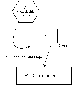
The RFID Edge Server PLC trigger driver converts PLC messages into trigger URIs for starting or stopping ALE event cycles. Figure 5-1 illustrates a typical PLC trigger setup.

For more information on how the RFID Edge Server communicates with and controls RFID devices by interacting with PLCs, see Controlling RFID Devices via PLC.
You configure PLC triggers in the edge.props file using the following steps:
| Note: | All property names shown in this section should be prefixed with com.connecterra.ale.plc, which is abbreviated [CCAP] in the properties below. |
edge.props and open the original for editing.Modbus transport named modbus0.# ModBus transport configuration
[CCAP].plcTransport.modbus0.metaName = ModBus
[CCAP].plcTransport.modbus0.hostname = plcHostName
[CCAP].plcTransport.modbus0.socketTimeout = 10000
[CCAP].plcTransport.modbus0.pollInterval = 10000
Simple message convention named simplemodbus0.[CCAP].plcMessageConvention.simplemodbus0.metaName = Simple
[CCAP].plcMessageConvention.simplemodbus0.plcTransport = modbus0
#Define inboundMessage `photoeye1' which is connected to a PLC pin with
#address 2052. (`d' is a convention referring to discrete input in the
#ModBus protocol.)
[CCAP].inboundMessage.photoeye1.plcMessageConvention = simplemodbus0
[CCAP].inboundMessage.photoeye1.receiveItem = d2052
[CCAP].inboundMessage.photoeye1.matchValues = true
#Define a trigger named `plcmessage' using the PLCTriggerDriver
com.connecterra.ale.triggerDriver.plcmessage.class=com.connecterra.ale.triggertypes.PLCTriggerDriver
edge.props and restart the Edge Server.
WebLogic RFID Edge Server includes a directional trigger driver that gets input from two source points, A and B, and determines if an object is moving from A to B or from B to A.
In the following example, two photoelectric sensors are positioned at a dock door, one at reading point A and one at reading point B. Tagged items move between points A and B in one direction at a time.
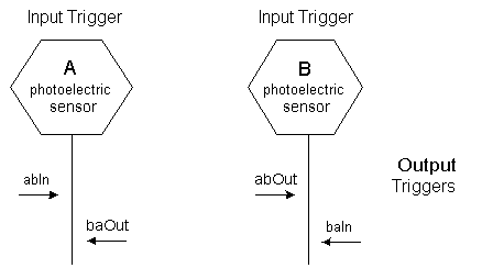
Figure 5-2 shows the input triggers, A and B, and the directional output triggers.

Moving items which first block photoelectric sensor A (generating output trigger abIn), then block sensor B (generating output trigger abOut), signal that AB traversal is finished. Moving items which block photoelectric sensor B first, then sensor A, (generating output triggers baIn then baOut), signal that BA traversal is finished.
| Note: | There is a maximum allowed travel time (T) between point A and point B. The trigger driver resets to the idle state after travel time T elapses, even if an object moves past photoelectric sensor A (moves in) but fails to move past photoelectric sensor B at the exit point (does not move out). |
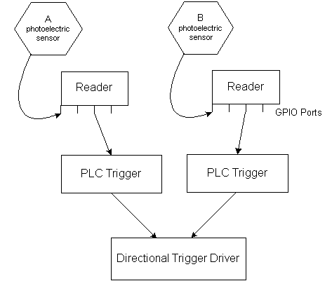
The directional trigger driver listens for input triggers. Input triggers might be PLC triggers, whose sources are PLC inbound messages which receive inputs from photoelectric sensors or other IO inputs, such as GPIO. Other types of triggers can also provide inputs, such as TCP triggers.

The directional trigger driver monitors the status (state change) of the input triggers, for example, when the photoelectric sensors are blocked. When the trigger driver receives the input trigger status, it generates trigger messages for trigger listeners in the event cycle, one listener for event start conditions and one for event stop conditions. When the start trigger is fired, the event cycle starts getting tag data; the event cycle stops when either the stop trigger fires or the cycle duration time expires.
You configure the directional trigger driver in the edge.props file by specifying the trigger driver class name, the timeout (in milliseconds), and two input triggers.
In the edge.props file example in Listing 5-1, the directional trigger name is door1; you can substitute the trigger name with any string.
#Define the directional trigger
#Trigger driver class name
com.connecterra.ale.triggerDriver.door1.class=com.connecterra.ale.triggertypes.DirectionTriggerDriver
#Directional trigger state timeout (if start trigger is fired, but stop
#trigger fails to fire, the directional trigger will reset to idle state
#after timeout period in ms)
com.connecterra.ale.triggerDriver.door1.timeout=10000
#input trigger URI at point `a'
com.connecterra.ale.triggerDriver.door1.aTrigger=plcmessage:photoeye1
#input trigger URI at point `b'
com.connecterra.ale.triggerDriver.door1.bTrigger=plcmessage:photoeye2
The directional trigger driver generates four output trigger URIs; for example, door1:abIn, door1:abOut, door1:baIn, door1:baOut. You use the trigger URI to specify the starting condition (for example, door1:abIn) or stopping condition (for example, door1:abOut) in the event cycle definition.
| Note: | abIn, abOut, baIn, and baOut are defined names and cannot be changed. |
The following examples illustrate two directional trigger configurations.
This example describes using the directional trigger driver with a Symbol XR400 reader (it does not work with the AR400 reader) and Symbol XR400 Reader Light Indication Box. Refer to the reader manufacturer's manual for the wiring details (Symbol Reader Manual, XR Series RFID Reader Integrator Guide, Part Number 72E-71773-03 Rev. A, February 2006).
Photoelectric sensors are connected to the Light Indication Box, then to the reader GPIO input ports (at pins #4 and #5). The GPIO port status is forwarded to the directional trigger driver using the Reader type PLC transport and the simple message convention.
To configure the directional trigger and the reader, perform the following steps:
edge.props file, define the following properties (see Listing 5-2):enableGPIO): true.mygpio (as defined in edge.props, bolded in Listing 5-2)#In edge.props file
#Define the PLC Transport type `Reader' named `mygpio'
com.connecterra.ale.plc.plcTransport.mygpio.metaName = Reader
#Define the message convention `Simple' named `simplegpio'
com.connecterra.ale.plc.plcMessageConvention.simplegpio.metaName = Simple
com.connecterra.ale.plc.plcMessageConvention.simplegpio.plcTransport =mygpio
#Define inboundMessage named `photoeye1'
com.connecterra.ale.plc.inboundMessage.photoeye1.plcMessageConvention = simplegpio
#Photoeye1 connected to the reader's GPIO input port pin #5
com.connecterra.ale.plc.inboundMessage.photoeye1.receiveItem = input5
com.connecterra.ale.plc.inboundMessage.photoeye1.matchValues = true
#Define inboundMessage named `photoeye2'
com.connecterra.ale.plc.inboundMessage.photoeye2.plcMessageConvention = simplegpio
#Photoeye2 connected to reader's GPIO input port pin #4
com.connecterra.ale.plc.inboundMessage.photoeye2.receiveItem = input4
com.connecterra.ale.plc.inboundMessage.photoeye2.matchValues = true
#Define the input trigger named `plcmessage' using the PLCTriggerDriver
com.connecterra.ale.triggerDriver.plcmessage.class=com.connecterra.ale.triggertypes.PLCTriggerDriver
#Define the directional trigger
#Driver class name
com.connecterra.ale.triggerDriver.door1.class=com.connecterra.ale.triggertypes.DirectionTriggerDriver
#Directional trigger state timeout (if start trigger is fired, but stop
#trigger fails to fire, the trigger will reset to idle state after timeout
#period in ms)
com.connecterra.ale.triggerDriver.door1.timeout=10000
#input trigger URI at point `a'
com.connecterra.ale.triggerDriver.door1.aTrigger=plcmessage:photoeye1
#input trigger URI at point `b'
com.connecterra.ale.triggerDriver.door1.bTrigger=plcmessage:photoeye2
The following example defines a directional trigger named door2 and uses two PLC IO inputs as input triggers. The PLC inputs are forwarded to the directional trigger driver using the ModBus type PLC transport and the simple message convention. The RFID Edge Server communicates with the PLC using the Modbus protocol. See Controlling RFID Devices via PLC.
The four output trigger URIs are door2:abIn, door2:abOut, door2:baIn, door2:baOut.
#In edge.props file
#Define the ModBus transport named `modbus0'
com.connecterra.ale.plc.plcTransport.modbus0.metaName = ModBus
com.connecterra.ale.plc.plcTransport.modbus0.hostname = localhost
com.connecterra.ale.plc.plcTransport.modbus0.socketTimeout = 10000
com.connecterra.ale.plc.plcTransport.modbus0.pollInterval= 1000
#Define the message convention `Simple'
com.connecterra.ale.plc.plcMessageConvention.simplemodbus0.metaName = Simple
com.connecterra.ale.plc.plcMessageConvention.simplemodbus0.plcTransport = modbus0
#Define inboundMessages `msg1' and `msg2', which are connected to PLC input
# IO 5 and 6 (`d' is a convention referring to discrete input in ModBus
#protocol)
com.connecterra.ale.plc.inboundMessage.msg1.plcMessageConvention = simplemodbus0
com.connecterra.ale.plc.inboundMessage.msg1.receiveItem = d5
com.connecterra.ale.plc.inboundMessage.msg1.matchValues = true
com.connecterra.ale.plc.inboundMessage.msg2.plcMessageConvention = simplemodbus0
com.connecterra.ale.plc.inboundMessage.msg2.receiveItem = d6
com.connecterra.ale.plc.inboundMessage.msg2.matchValues = true
#Define the input trigger named `plcmessage' using the PLCTriggerDriver
com.connecterra.ale.triggerDriver.plcmessage.class=com.connecterra.ale.triggertypes.PLCTriggerDriver
#Define the directional trigger `door2' - timeout = 10000ms
com.connecterra.ale.triggerDriver.door2.class=com.connecterra.ale.triggertypes.DirectionTriggerDriver
com.connecterra.ale.triggerDriver.door2.timeout=10000
#input trigger at point `a'
com.connecterra.ale.triggerDriver.door2.aTrigger=plcmessage:msg1
#input trigger at point `b'
com.connecterra.ale.triggerDriver.door2.bTrigger=plcmessage:msg2


|