Product Description
|
|
Get Adobe Reader |
Software Architecture Overview
The following sections provide an overview of the WebLogic Network Gatekeeper moduler software architecture:
- Overview
- Processes
- Service distribution
- Scalability
- Software configuration example
- Resource sharing contexts
Overview
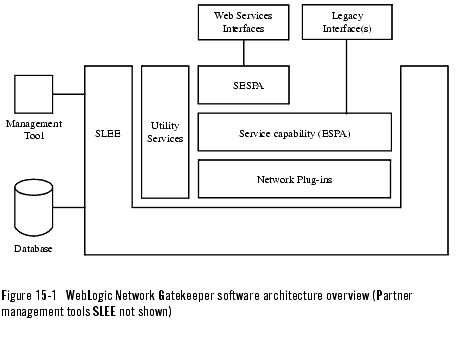
WebLogic Network Gatekeeper has a modular software architecture where most functions run as services in a CORBA based Service Logic Execution Environment (SLEE). The main WebLogic Network Gatekeeper software modules are:
- SLEE
- SLEE services including:
- Utility services (for a list of utility services, see SLEE utility services)
- Service capability modules
- SESPA (stateless adapters for web service access)
- Service capability manager
- Plug-in manager
- Partner management tools
- SLEE database
- ORB
- WebLogic Network Gatekeeper management tool (not run within the SLEE)
- SLEE agent (not run within the SLEE)
The basic software architecture is shown in Figure 15-1, WebLogic Network Gatekeeper software architecture overview (Partner management tools SLEE not shown), on page 15-3. Note that the partner management tool service is run in a separate SLEE. For descriptions of the individual software modules, see Software Module Descriptions.
Processes
The following are the most important WebLogic Network Gatekeeper related processes:
- SLEE processes (one for each SLEE)
- SLEE agent processes (SLEE process supervision, one for each SLEE)
- Database processes
- Trace processes
When a SLEE process is started, the installed SLEE services are automatically started.
Service distribution
All SLEE service types can be distributed to execute in any number of SLEEs in the system. When installing a new SLEE service instance, it is automatically registered in all other SLEEs in the system. Service capability modules are registered in the service capability manager, and the network plug-ins are registered in the plug-in manager. All SLEEs have the utility services installed by default.
Capacity requirements decide the number of instances of each SLEE service to be installed in the system. For high availability reasons, at least two instances of each service shall be installed
Scalability
The capacity of the WebLogic Network Gatekeeper system is changed by changing the number of SLEEs running in the system. When adding a SLEE to an WebLogic Network Gatekeeper, a new server also has to be added.
Software configuration example
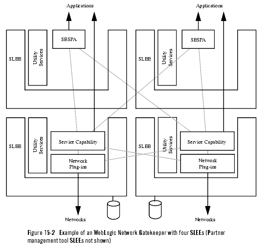
The following example describes an WebLogic Network Gatekeeper configuration with four SLEEs, one on each server. Two SLEEs have SESPA and Service capability modules (ESPA), and utility services installed. These SLEEs handle the communication with the applications. The two other SLEEs have network plug-ins and utility services installed. These SLEEs handle the network communication.
The example is shown in Figure 15-2.
Scaling the system
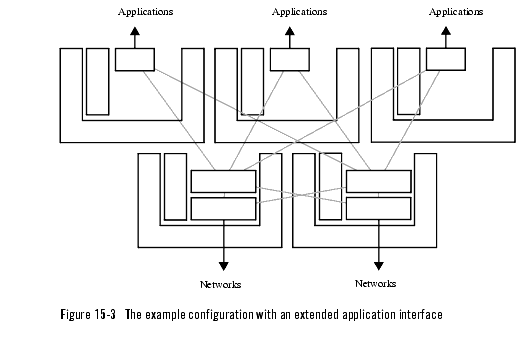
If, for example a service capability module becomes overloaded, it is recommended to install a new server and SLEE with the same set of services as the other two SLEEs handling the application communication. This approach, with dedicated SLEEs, simplifies OAM of the system compared to having different sets of SLEE services installed on every server.
Resource sharing contexts
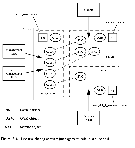
The purpose of the concept with resource sharing contexts is to separate different types of traffic execution and to separate the traffic related execution from OAM related execution. In addition, resource sharing contexts can be used to separate the system's subnets from each other.
Each resource sharing context has its own ORB and name service. For the resource sharing contexts it is possible to specify:
Figure 15-4, Resource sharing contexts (management, default and user def 1), on page 15-7 show a SLEE with three resource sharing context contexts. The management and default resource sharing contexts are default resource sharing context. Depending on the type of applications, system configuration and so on, more resource sharing contexts can be defined.


