

|
The following sections provide an overview of WebLogic Network Gatekeeper's software architecture:
There are two functional maps to keep in mind in understanding the basic software architecture of WebLogic Network Gatekeeper: the traffic path map and the SLEE map.
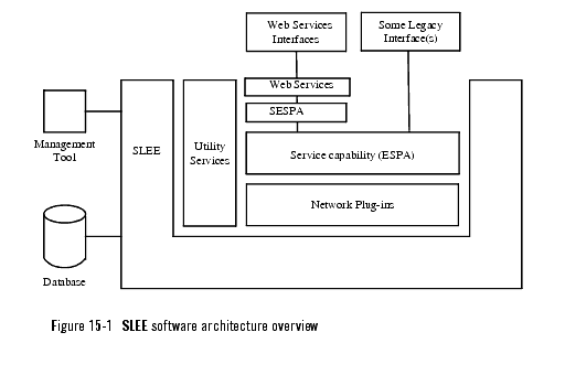
The traffic path map follows the flow of traffic as it moves through the Network Gatekeeper. It consists of northbound interfaces, service capability modules, and network plug-ins. The first two of these units are subdivided. Most northbound interfaces run in the Web Services layer, which includes an embedded Tomcat instance for handling SOAP messaging. Some legacy interfaces, however, connect directly to the ESPA layer. The service capability modules are divided into two parts: SESPA and ESPA. SESPA is an adaptation layer that reconfigures stateless Web Services requests into the stateful requests that ESPA requires. Individual service capabilities often thus exist in two stages: Access, for example, has a SESPA part and an ESPA part. For more information on SESPA, see SESPA modules
All the functionality of the Web Services, SESPA, ESPA, and network plug-in layers run as services inside CORBA based Service Logic Execution Environments (SLEEs). SLEEs offer a flexible and highly modular software environment that provides support for scalability and ease of operation. Seen from this perspective, the main WebLogic Network Gatekeeper software modules are:
The basic SLEE architecture is shown in Figure 15-1.

For more detailed descriptions of the individual software modules, see SLEE Software Module Descriptions.
| Note: | The Partner Relationship Management Interfaces service should execute in a separate SLEE, and is therefore not shown in the diagram. |
The following are the most important SLEE related processes:
When a SLEE process is started, the installed SLEE services are automatically started.
All SLEE service types can be distributed to any number of SLEEs in the system. SLEE service instances installed in one SLEE are automatically registered in all other SLEEs in the system. ESPA modules are registered in the service capability manager, and network plug-ins are registered in the plug-in manager. All SLEEs have the utility services installed by default.
Capacity requirements determine the number of instances of each SLEE service to be installed in the system. For high availability reasons, at least two instances of each service should be installed
The capacity of WebLogic Network Gatekeeper system is changed by changing the number of SLEEs running in the system. As every SLEE requires its own server, adding a SLEE requires adding a server.
The following graphic (Figure 15-2) shows a Network Gatekeeper configuration with four SLEEs, one on each of four servers. Two SLEEs have SESPA modules and utility services installed. The two other SLEEs have ESPA modules and network plug-ins and utility services installed.

To cope with the system becoming more heavily loaded, it is usually best to install new servers and SLEEs with sets of services that parallel the existing distribution. If the service capabilities modules in the lower two SLEES (Figure 15-2) above, for example, became overloaded, the recommended way of handling it (Figure 15-3) would be to add a third server/SLEE with exactly the same set of services. This dedicated SLEE approach simplifies OAM of the system as a whole.

Resource sharing contexts provide an additional method of separating differing kinds of data flow within WebLogic Network Gatekeeper. Different types of traffic execution can be partitioned off into different contexts, and OAM related execution can be kept separate from all traffic execution. Resource sharing contexts can also be used to separate the system's subnets from each other.
Each resource sharing context has its own ORB and name service. For each resource sharing context it is possible to specify:
Figure 15-4 below shows a SLEE with three resource sharing contexts. The Management and Default resource sharing contexts exist by default. Depending on the type of applications supported, system configuration, and so on, more resource sharing contexts - such as User Def 1 below - can be added.


|