Configuring and Managing WebLogic SIP Server
|
|
Overview of the WebLogic SIP Server Architecture
The following sections provide an overview of the WebLogic SIP Server 2.1 architecture:
- Goals of the WebLogic SIP Server Architecture
- Load Balancer
- Engine Tier
- Data tier
- Example Hardware Configuration
- Alternate Configurations
Goals of the WebLogic SIP Server Architecture
WebLogic SIP Server 2.1 is designed to provide a highly scalable, highly available, performant server for deploying SIP applications. The WebLogic SIP Server 2.1 architecture is simple to manage and easily adaptable to make use of available hardware. The basic architecture consists of several major components:
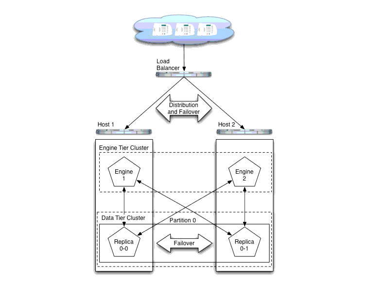
Figure 1-1shows the components of a basic WebLogic SIP Server installation. The sections that follow describe each component of the architecture in more detail.
Figure 1-1 WebLogic SIP Server 2.1 Architecture
Load Balancer
Although it is not provided as part of the WebLogic SIP Server product, a load balancer (or multiple load balancers) is an essential component of any production WebLogic SIP Server installation. The primary goal of a load balancer is to provide a single public address that distributes incoming SIP requests to multiple servers in the WebLogic SIP Server engine tier. Distribution of requests ensures that WebLogic SIP Server engines are fully utilized.
Most load balancers have configurable policies to ensure that client requests are distributed according to the capacity and availability of individual machines, or according to any other load policies required by your installation. Some load balancers also provide special features for managing SIP network traffic, such as support for routing policies based on source IP address, port number, or other fields available in SIP message headers. Many load balancer products also provide additional fault tolerance features for telephony networks.
In a WebLogic SIP Server installation, the load balancer is also essential for performing maintenance activities such as upgrading individual servers (WebLogic SIP Server software or hardware) or upgrading applications without disrupting existing SIP clients. The Administrator modifies load balancer policies to move client traffic off of one or more servers, and then performs the required upgrades on the unused server instances. Afterwards, the Administrator modifies the load balancer policies to allow client traffic to resume on the upgraded servers.
BEA provides detailed information for setting up load balancers to monitor the health and availability of individual server instances in the WebLogic SIP Server engine tier for basic load distribution. See http://dev2dev.bea.com/. See also Configuring Load Balancer Addresses to configure a load balancer used with WebLogic SIP Server and Upgrading Software and Applications in a Production Environment to use a load balancer to perform system and application upgrades.
Engine Tier
The engine tier is a cluster of WebLogic SIP Server instances that hosts the SIP Servlets that provide features to SIP clients. Server instances in the engine tier host only SIP Servlets—SIP session information is not persisted in the engine tier, but is obtained by querying the data tier.
The primary goal of the engine tier is to provide maximum throughput and low response time to SIP clients. As the number of calls, or the average duration of calls to your system increases, you can easily add additional server instances to the engine tier to manage the additional load.
Note that although the engine tier consists of multiple WebLogic SIP Server instances, you manage the engine tier as a single, logical entity; SIP Servlets are deployed uniformly to all server instances (by targeting the cluster itself) and the load balancer need not maintain an affinity between SIP clients and servers in the engine tier.
Note: WebLogic SIP Server start scripts use default values for many JVM parameters that affect performance. For example, JVM garbage collection and heap size parameters may be omitted, or may use values that are acceptable only for evaluation or development purposes. In a production system, you must rigorously profile your applications with different heap size and garbage collection settings in order to realize adequate performance. See Tuning JVM Garbage Collection for Production Deployments for suggestions about maximizing JVM performance in a production domain.
Data tier
The data tier is a cluster of WebLogic SIP Server instances that provides a high-performance, highly-available, in-memory database for storing and retrieving the session state data for SIP Servlets. The goals of the data tier are as follows:
- To provide reliable, performant storage for session data required by SIP applications in the WebLogic SIP Server engine tier.
- To enable administrators to easily scale hardware and software resources as necessary to accommodate the session state for all concurrent calls.
Within the data tier, session data is managed in one or more "partitions" where each partition manages a fixed portion of the concurrent call state. For example, in a system that uses two partitions, the first partition manages one half of the concurrent call state (for example, sessions A through M) while the second partition manages another half of the concurrent call states (sessions N through Z). With three partitions, each partition manages a third of the call state, and so on. Additional partitions can be added as necessary to manage a large number of concurrent calls.
Within each partition, multiple servers can be added to provide redundancy and failover should other servers in the partition fail. When multiple servers participate in the same partition, the servers are referred to as "replicas" because each server maintains a duplicate copy of the partition's call state. For example, if a two-partition system has two servers in the first partition, each server manages a replica of call states A through M. If one or more servers in a partition fails or is disconnected from the network, any available replica can automatically provide call state data to the engine tier. In WebLogic SIP Server 2.1, the data tier can have a maximum of three replicas, providing two levels of redundancy.
See Configuring Data Tier Partitions and Replicas for more information about configuring the data tier for high availability. See Determining Performance Goals for information about planning the hardware resources required in the data tier.
Example Hardware Configuration
WebLogic SIP Server's flexible architecture enables you to configure engine and data tiers in a variety of ways to support high throughput and/or provide high availability. See Capacity Planning for WebLogic SIP Server Deployments for detailed information about scaling the engine and data tiers to suit the needs of your organization.
Alternate Configurations
Not all WebLogic SIP Server requirements require the performance and reliability provided by multiple servers in the engine and data tiers. On a development machine, for example, it is generally more convenient to deploy and test applications on a single server, rather than a cluster of servers.
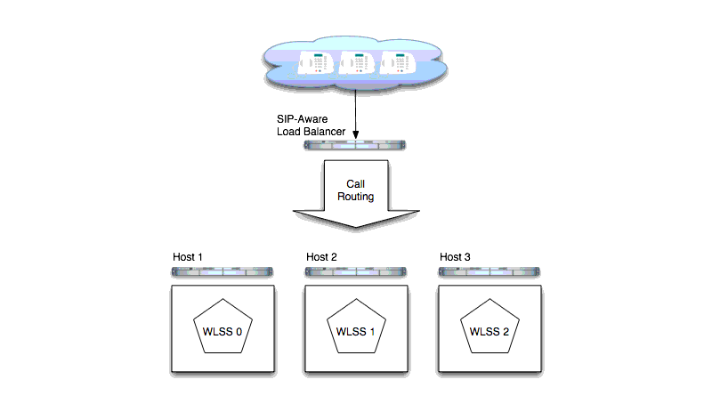
WebLogic SIP Server enables you to combine engine and data tier services on a single server instance when replicating call states is unnecessary. In a combined-tier configuration, the same WebLogic SIP Server instance provides SIP Servlet container functionality and also manages the call state for applications hosted on the server. Although the combined-tier configuration is most commonly used for development and testing purposes, it may also be used in a production environment if replication is not required for call state data. Figure 1-2 shows an example deployment of multiple combined-tier servers in a production environment.
Figure 1-2 Single-Server Configurations with SIP-Aware Load Balancer
Because each server in a combined-tier server deployment manages only the call state for the applications it hosts, the load balancer must be fully "SIP aware." This means that the load balancer actively routes multiple requests for the same call to the same WebLogic SIP Server instance. If requests in the same call are not pinned to the same server, the call state cannot be retrieved. Also keep in mind that if a WebLogic SIP Server instance fails in the configuration shown in Figure 1-2, all calls handled by that server are lost.
