

|
The following sections describe common network architectures used in production deployments, and explain how WebLogic SIP Server is configured to run in those architectures:
Most production installations of WebLogic SIP Server are contain one or more of the following characteristics:
A combination of these network elements can make it difficult to understand how elements interact with one another, and how a particular combination of elements or configuration options affects the contents of a SIP message or transport protocol datagram.
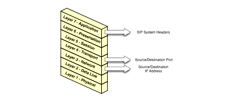
The sections that follow attempt to describe common WebLogic SIP Server network architectures and explain how servers are configured in each architecture. The sections also explain how information in SIP messages and transport datagrams is affected by each configuration. Figure 2-1 shows the typical Open Systems Interconnect (OSI) model layers that can be affected by different network configurations.

Layer 3 (Network) and Layer 4 (Transport) contain the source or destination IP address and port numbers for both outgoing and incoming transport datagrams. Layer 7 (Application) may also be affected because the SIP protocol specifies that certain SIP headers include addressing information for contacting the sender of a SIP message.
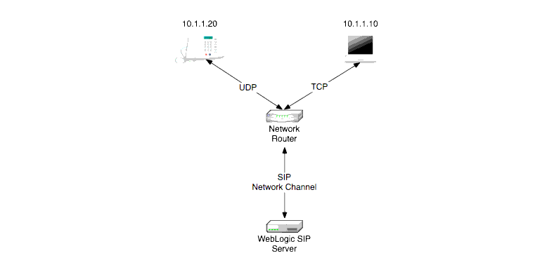
In a simple network configuration for a server having a single NIC, one or more network channels may be created to support SIP messages over UDP and TCP, or SIPS over TLS. It is helpful to understand how this simple configuration affects information in the OSI model, so that you can understand how more complex configurations involving multihomed hardware and load balancers affect the same information.

Figure 2-2 shows a single engine tier server instance with a single NIC. The server is configured with one network channel supporting SIP over UDP and TCP. (SIP channels always support both UDP and TCP transports; you cannot support only one of the two.) Figure 2-2 also shows two clients communicating with the server, one over UDP and one over TCP.
For the TCP transport, the outgoing datagram (delivered from WebLogic SIP Server to the UA) contains the following information:
Incoming TCP datagrams (delivered from the UA to WebLogic SIP Server) contain the following information:
For outgoing UDP datagrams, the OSI layer information contains the same information as with TCP transport. For incoming UDP datagrams, the OSI layer information is the same as TCP except in the case of incoming datagram Layer 4 information. For incoming UDP datagrams, Layer 4 contains either:
By default WebLogic SIP Server allocates ports from the ephemeral port number range of the underlying operating system for outgoing UDP datagrams. WebLogic SIP Server allows external connections to use an ephemeral point as the destination port number, in addition to the port number configured in the network channel. In other words, WebLogic SIP Server automatically listens on all ephemeral ports that the server allocates. You can optionally disable WebLogic SIP Server's use of ephemeral port numbers by specifying the following option when starting the server:
You can determine WebLogic SIP Server's use of a particular ephemeral port by examining the server log file:
<Nov 30, 2005 12:00:00 AM PDT> <Notice> <WebLogicServer> <BEA-000202> <Thread "SIP Message Processor (Transport UDP)" listening on port 35993.>
WebLogic SIP Server network channels provide a SourcePorts attribute that you can use to configure one or more static ports that a server uses for originating UDP packets.
| WARNING: | BEA does not recommend using the SourcePorts custom property in most configurations because it degrades performance. Configure the property only in cases where you must specify the exact ports that WebLogic SIP Server uses to originate UDP packets. |
To configure the SourcePorts property, use a JMX client such as WLST or directly modify a network channel configuration in config.xml to include the custom property. SourcePorts defines an array of port numbers or port number ranges. Do not include spaces in the SourcePorts definition - use only port numbers, hyphens ("-") to designate ranges of ports, and commas (",") to separate ranges or individual ports. See Listing 2-1 for an example configuration.
<network-access-point>
<name>sip</name>
<protocol>sip</protocol>
<listen-port>5060</listen-port>
<public-port>5060</public-port>
<http-enabled-for-this-protocol>false</http-enabled-for-this-protocol>
<tunneling-enabled>false</tunneling-enabled>
<outbound-enabled>true</outbound-enabled>
<enabled>true</enabled>
<two-way-ssl-enabled>false</two-way-ssl-enabled>
<client-certificate-enforced>false</client-certificate-enforced>
<custom-properties>SourcePorts=5060</custom-properties></network-access-point>
Engine tier servers in a production deployment frequently utilize multihomed server hardware, having two or more NICs. Multihomed hardware is typically used for one of the following purposes:
The configuration requirements and OSI layer information differ depending on the use of multihomed hardware in your system. When multiple NICs are used to provide redundant connections within a subnet, servers are generally configured to listen on all available addresses (IP_ANY) as described in Multihomed Servers Listening On All Addresses (IP_ANY).
When using multiple NICs to support different subnets, you must configure multiple network on the server for each different NIC as described in Multihomed Servers Listening on Multiple Subnets.
The simplest multihome configuration enables a WebLogic SIP Server instance to listen on all available NICs (physical NICs as well as logical NICs), sometimes described as IP_ANY. To accomplish this, you simply configure a single network channel and specify a channel listen address of 0.0.0.0.
Note that you must configure the 0.0.0.0 address directly on the server's network channel. If you specify no IP address in the channel, the channel inherits the listen address configured for the server instance itself. See Configuring Engine Servers to Listen on Any IP Interface (0.0.0.0 or ::).
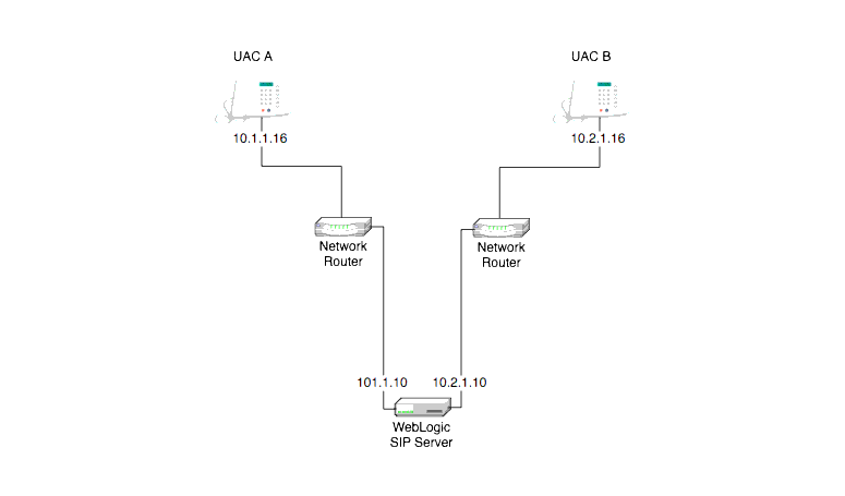
Multiple NICs can also be used in engine tier servers to listen on multiple subnets. The most common configuration uses WebLogic SIP Server to proxy SIP traffic from one subnet to another where no direct access between subnets is permitted. Figure 2-3 shows this configuration.

To configure the WebLogic SIP Server instance in Figure 2-3 you must define a separate network channel for each NIC used on the server machine. Listing 2-2 shows the config.xml entries that define channels for the sample configuration.
<NetworkAccessPoint ListenAddress="10.1.1.10" ListenPort="5060" Name="sipchannelA" Protocol="sip"/>
<NetworkAccessPoint ListenAddress="10.2.1.10" ListenPort="5060" Name="sipchannelB" Protocol="sip"/>
When WebLogic SIP Server is configured to listen on multiple subsets, a feature called the route resolver is responsible for the following activities:
For example, in the configuration shown in Figure 2-3, WebLogic SIP Server must add the correct subnet address to SIP system headers and transport datagrams in order for each UA to continue processing SIP transactions. If the wrong subnet is used, replies cannot be delivered because neither UA can directly access the other UA's subnet.
The route resolver works by determining which NIC the operating system will use to send a datagram to a given destination, and then examining the network channel that is associated with that NIC. It them uses the address configured in the selected network channel to populate SIP headers and Layer 3 address information.
For example, in the configuration shown in Figure 2-3, an INVITE message sent from WebLogic SIP Server to UAC B would have a destination address of 10.2.1.16. The operating system would transmit this message using NIC B, which is configured for the corresponding subnet. The route resolver associates NIC B with the configured sipchannelB and embeds the channel's IP address (10.2.1.10) in the VIA header of the SIP message. UAC B then uses the VIA header to direct subsequent messages to the server using the correct IP address. A similar process is used for UAC A, to ensure that messages are delivered only on the correct subnet.
IP aliasing assigns multiple logical IP addresses to a single NIC, and is configured in the underlying server operating system. If you configure IP aliasing and all logical IP addresses are within the same subnet, you can simply configure WebLogic SIP Server to listen on all addresses as described in Multihomed Servers Listening On All Addresses (IP_ANY).
If you configure IP aliasing to create multiple logical IP addresses on different subnets, you must configure a separate network channel for each logical IP address. In this configuration, WebLogic SIP Server treats all logical addresses as separate physical interfaces (NICs) and uses the route resolver to populate OSI Layer 4 and Layer 7 information based on the configured channel.
In addition to providing failover capabilities and distributing the client load across multiple servers, a load balancer is also an important tool for configuring the network information transmitted between clients and servers. The sections that follow describe common load balancer configurations used with WebLogic SIP Server.
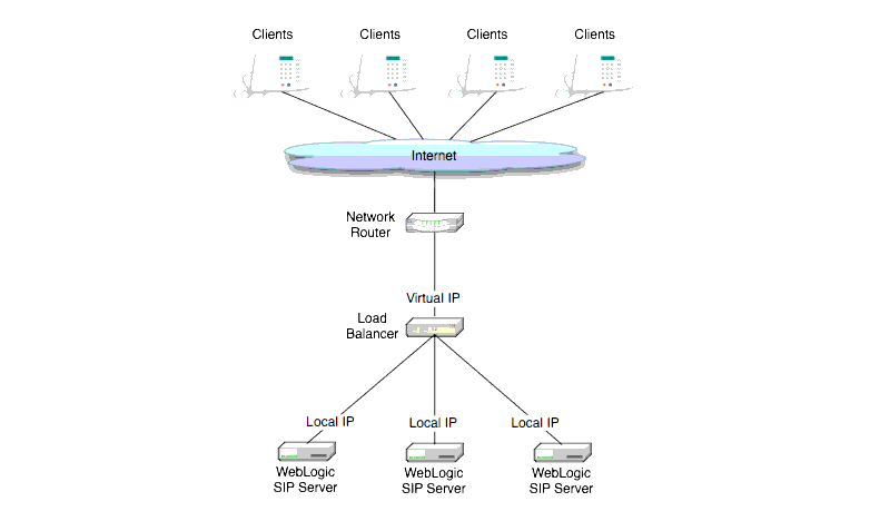
The most common load balancer configuration utilizes a single load balancer that gates access to a cluster of engine tier servers, as shown in Figure 2-4.

To configure WebLogic SIP Server for use with a single load balancer as in Figure 2-4, configure one or more network channels for each server, and configure the public address of each channel with the Virtual IP address of the load balancer. In this configuration, WebLogic SIP Server embeds the load balancer IP address in SIP message system headers to ensure that clients can reach the cluster for subsequent replies. Managing WebLogic SIP Server Network Resources presents detailed steps for configuring network channels with load balancer addresses.
| Note: | Although some load balancing switches can automatically re-route all SIP messages in a given call to the same engine tier server, this functionality is not required with WebLogic SIP Server installations. See Alternate Configurations in Configuring WebLogic SIP Server for more information. |
Multiple load balancers (or a multihomed load balancer) can be configured to provide several virtual IP addresses for a single WebLogic SIP Server cluster. To configure WebLogic SIP Server for use with a multihomed load balancer, you create a dedicated network channel for each load balancer or local server NIC, and set the channel's public address to the virtual IP address of the appropriate load balancer. In this configuration, the route resolver associates a configured channel with the NIC used for originating SIP messages. The public address of the selected channel is then used for populating SIP system messages. See Understanding the Route Resolver.
In the most common case, a load balancer is configured using destination NAT to provide a public IP address that clients use for communicating with one or more internal (private) WebLogic SIP Server addresses. Load balancers may also be configured using source NAT, which modifies the Layer 3 address information originating from a private address to match the virtual IP address of the load balancer itself.
With the default route resolver behavior, a WebLogic SIP Server engine originates UDP packets having a source IP address that matches the address of a local NIC (the private address). This can be problematic for applications that try to respond directly to the Layer 3 address embedded in the transport packet, because the local server address may not be publicly accessible. If your applications exhibit this problem, BEA recommends that you configure the load balancer to perform source NAT to change the transport Layer 3 address to a publicly-accessible virtual IP address.
| WARNING: | Using the WebLogic SIP Server IP masquerading functionality can lead to network instability, because it requires duplicate IP addresses on multiple servers. Production deployments must use a load balancer configured for source NAT, rather than IP masquerading, to ensure reliable network performance. |
If you choose not to enable source NAT on your load balancer, WebLogic SIP Server provides limited IP masquerading functionality. To use this functionality, configure a logical address on each engine tier server using the public IP address of the load balancer for the cluster. (Duplicate the same logical IP address on each engine tier server machine). When a local server interface matches the IP address of a configured load balancer (defined in the public address of a network channel), WebLogic SIP Server uses that interface to originate SIP UDP messages, and the Layer 3 address contains a public address.
You can disable WebLogic SIP Server's IP masquerading functionality by using the startup option:


|