


|
There are several core implementation patterns for WLI applications, as explained in the following sections:
JPDs are of several types and are designed with the following intrinsic characteristics:
| Note: | Composite processes have more complex exception management because of the multiple calls. |
Several patterns of JPDs have resulted from combinations of these characteristics. The following sections describe these patterns in brief:
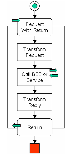
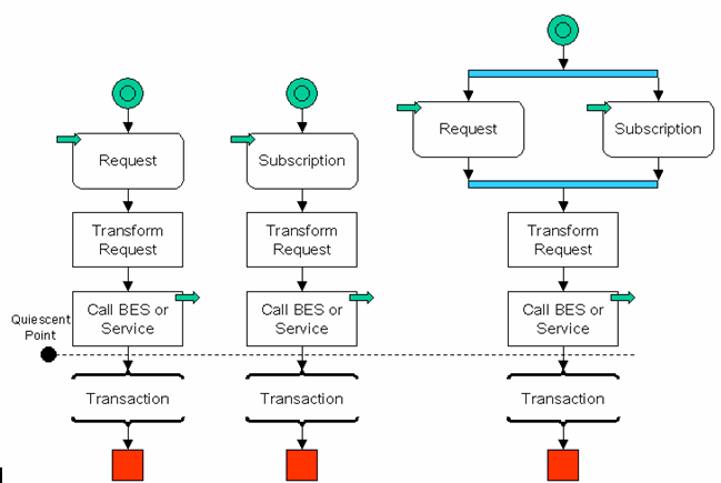
Use this pattern illustrated in Figure 6-1 to implement some of the fastest processes. The standard usage is for simple access to a backend system or to implement helper processes.
Use this pattern illustrated in Figure 6-2 to implement some of the fastest processes. The standard usage is for simple access to a backend system, when de-coupling with the process client is required.
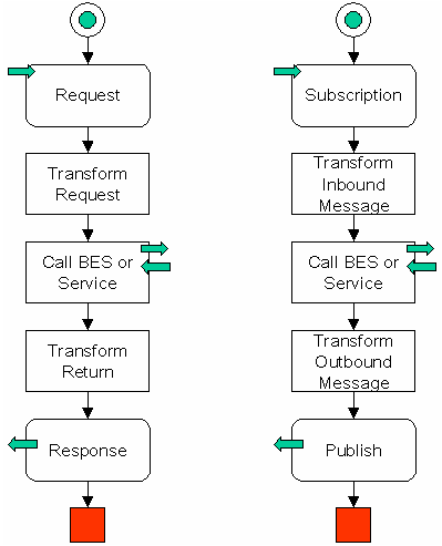
Use this pattern illustrated in Figure 6-3 to implement some of the fastest processes. The standard usage is to access backend systems in event-driven situations.
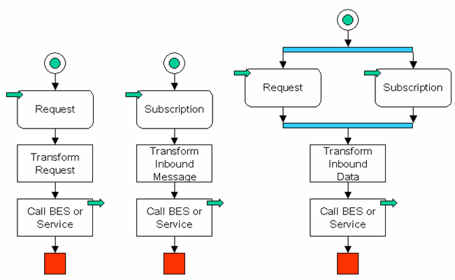
This pattern is not as fast as its stateless equivalent. Use this pattern illustrated in Figure 6-4 to access backend systems that provide an asynchronous interface.
This pattern is very rare because most of the one-way services are stateless and so there is no need to wait for an answer. Use this pattern illustrated in Figure 6-5 to quickly access a backend system in event-driven situation where a call that is waiting is required.
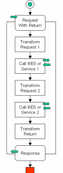
Use this pattern illustrated in Figure 6-6 to implement integration logic that requires good performance and coupling with the client.
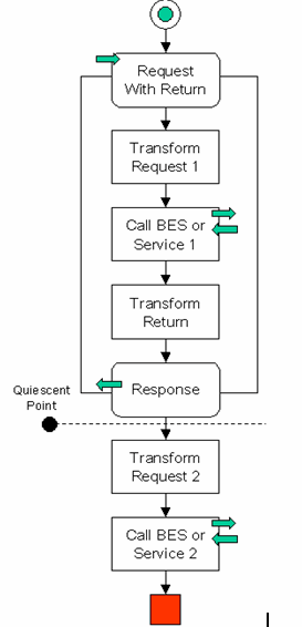
This pattern represents an unusual case, where the logic is implemented after the client has received a response. Use this pattern illustrated in Figure 6-7 to enable a stateful process that runs for a period of time, and is started by a synchronous request or response. Once the synchronous reply is sent, the process moves to a traditional asynchronous model.
This pattern illustrated in Figure 6-8 is a standard method to implement integration logic that requires good performance while maintaining de-coupling from its client. It can also be used to access a backend system when de-coupling from the caller is required. It is not always possible to implement this pattern as it requires all the resources used to be stateless.
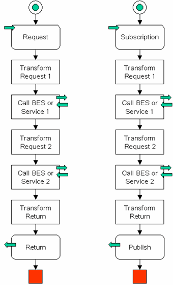
Use this pattern illustrated in Figure 6-9 to implement integration logic that requires good performance in event-driven situations.
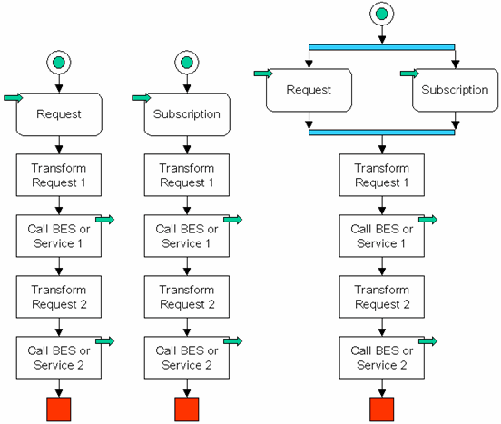
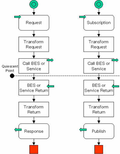
Use this pattern illustrated in Figure 6-10 when the stateless version of the same pattern is not possible, as at least one of the resources contains an asynchronous interface. It is also used as a standard pattern for long-running processes.
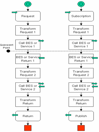
This pattern is not common as most of the one-way services are usually stateless and there is no need to wait for an answer. Use this pattern illustrated in Figure 6-11 to implement integration logic in event-driven scenarios, and where a call that is waiting is also required.
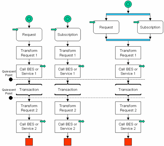
This section re-groups useful patterns, which can be used in combination with one of the core patterns.
You can create a business process containing a client request node with a sync or async callback name attribute property, to enable synchronous clients to interact with business processes that have asynchronous interactions with resources. The client request node property holds the name of the callback method that the associated client response node uses. The client request and client response nodes delineate the activities (including asynchronous activities) that occur while the client is blocking the process. After setting this property, generate the sync-to-async WSDL. The synchronous WSDL generation process replaces the SOAP address of the service with a modified SOAP address. The modified address causes the synchronous servlet to process the client request and subsequent return action. A sample of the generated service entry is as follows:
<service name="syncAsync"><port name="syncAsyncSoap" binding="s0: syncAsyncSoap"><soap: address location="http://localhost:7001/SyncAsyncWeb/processes/syncAsync.jpd"/></port> <service name="syncAsync">
<port name="syncAsyncSoap" binding="s0: syncAsyncSoap">
<soap:address
location="http://localhost:7001/sync2AsyncIM/SyncAsyncWeb/processes/syncAsync.sync2JPD"/>
The de-synchronizer pattern allows you to asynchronously call a synchronous process. This is recommended if:
Implement the process in Figure 6-12 to provide an asynchronous interface to a synchronous process.
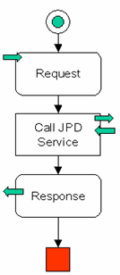
This is a simple proxy process. The signature of the request and the response should remain the same as that of the original service. The de-synchronizer passes its input values to the sub-process and sends the return value to the caller of the sub-process.
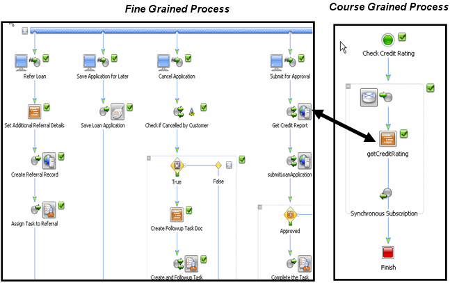
Figure 6-13 illustrates an example of how you can use a combination of course-grained and fine grained processes. A course-grained process assigns specific work to a number of fine-grained processes.
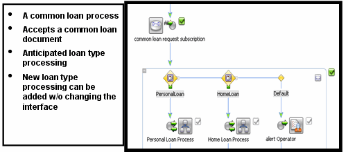
This pattern illustrated in Figure 6-14 shows how you can create a loosely coupled process using a common messaging interface through message brokers, based upon a Publish and Subscribe architecture.
You can use the following controls to define a dynamic, property driven process:
Figure 6-15 illustrates an example of an agile and dynamic process with a Register and Table look-up.
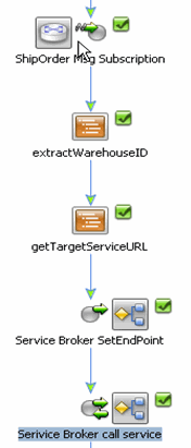
The features of this process are as follows:


|