


|

|
|
|
|
Creating a Workflow
This section of the tutorial shows you how to create the Order Processing workflow. After a high-level overview of the workflow, we do the following:
Overview of the Order Processing Workflow Design
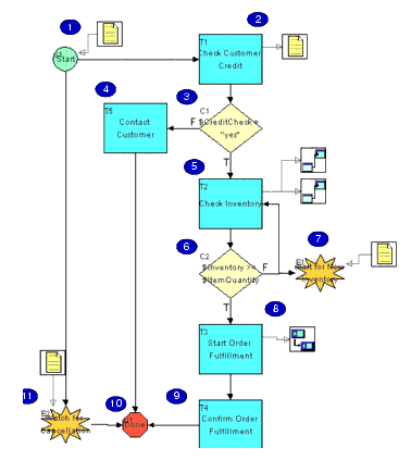
The Order Processing workflow handles the processes from receiving the order to checking customer credit and checking inventory. It then passes control to the Order Fulfillment workflow, which handles shipping and invoicing. When the Order Fulfillment process is complete, control is returned to the Order Processing workflow, which confirms the order completion.
The following figure provides a high-level depiction of the workflow in Interface View. The numbered steps in the figure are described in the table that follows the figure, which maps the real-world processes to the workflow model.
Figure 4-1 Order Processing Workflow: Interface View
Table 4-1 Order Processing Workflow Summary
Creating a Template
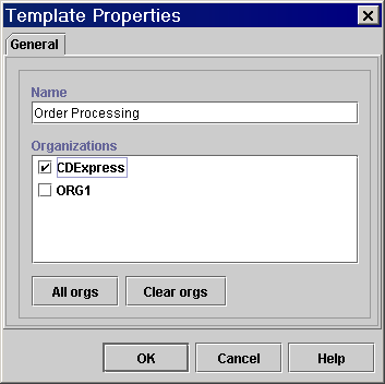
When you create a workflow template, you specify the organizations with which you would like to associate it.
Note: If you associate a template with multiple organizations, any changes you make to the template are automatically reflected when viewing the template from different organizations.
To create the Order Processing template:
Figure 4-2 Template Properties Dialog Box
Creating a Template Definition
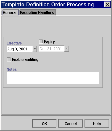
When you create a template definition, you specify effective and expiry dates. By default, the effective date is the current date and there is no expiry date.
To create the template definition for the new workflow template:
Figure 4-3 Template Definition Order Processing Dialog Box
The workflow design window opens, with a simple default workflow containing a start node, a task node, and a done node, and two actions within the task node: Assign Task to User WorkflowAttribute("Initiator") and Mark Task as Done. These are the minimum workflow objects that are required to define an executable workflow.
Figure 4-4 Workflow Design Window
Drawing the Flow
You use the toolbar icons in the workflow design window to draw your flow. In this section we draw the Order Processing workflow by placing node shapes in the workflow design area, and then connecting and renaming them.
Placing Shapes
Our workflow design requires the following shapes:
To add a shape, do the following:
Note: Shapes are initially assigned a number when you place them. However, the final order of the shapes within the flow does not matter.
Renaming Nodes
Before we connect the nodes, let us rename them, to make it easier to identify them.
Note: Decision nodes must be named with expressions, usually containing variables. Because you must first create the variables to be used in conditional expressions, you will name the decision nodes in Defining Workflow Nodes.
To rename task and event nodes:
Table 4-2 Order Processing Workflow: Task and Event Nodes
|
Node |
Name |
|---|---|
|
T1 |
Check Customer Credit |
|
T2 |
Confirm Order Fulfillment |
|
T3 |
Check Inventory |
|
T4 |
Start Order Fulfillment |
|
T5 |
Contact Customer |
|
E1 |
Wait for New Inventory |
|
E2 |
Watch for Cancellation |
Note: Do not worry if your names do not correspond exactly to the node numbers in the table. The final order of the shapes within the flow does not matter.
Arranging Shapes and Connecting Nodes
We now move the shapes around and connect the nodes so that the final flow appears as in the following figure.
Figure 4-5 Order Processing Workflow: Final Design
To move a shape, drag and drop it anywhere within the workflow design area. To make a connection, you can use one of two approaches: from the toolbar or from a Properties dialog box for the node. To make a connection from the toolbar: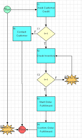
To make a connection from a node's Properties dialog box:
To delete a connection, you can use one of two approaches: from within the drawing area or from the Properties dialog box for a node.
To delete a connection from within the drawing area:
To delete a connection from a node's Properties dialog box:
Adding a Workflow Label
In Understanding Workflow Expressions: Viewing the Set Workflow Variable and Assign Task to User Actions, you saw that in the Order Processing Trigger workflow, the variable OrderID was set to be incremented by 1. Now we will create a label which displays that information in the run-time applications, so that each instance of the workflow will have a unique label.
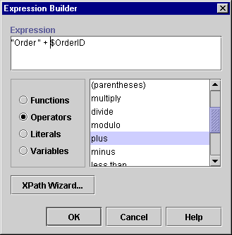
To create a workflow label, you specify a workflow expression. To display the label Order number, we use the following expression.
Listing 4-1 Workflow Label
"Order " + $OrderID
To add our label, we must also create the variable OrderID that corresponds to the variable that already exists in the Order Processing Trigger workflow. Since we can create a variable from within the Expression Builder, the following procedure combines creating a variable with defining an expression.
Creating an Expression with the Expression Builder
To create the OrderID variable and define the workflow label:
Note: This field is not available when you first create the template definition, but only after you have opened it.
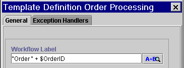
Figure 4-6 Order Processing Template Definition Dialog Box: Workflow Label Field
 button next to the Workflow Label field. The Expression Builder appears.
Figure 4-7 Creating a Variable from the Expression Builder
Figure 4-8 Variable Properties Dialog Box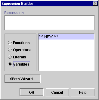
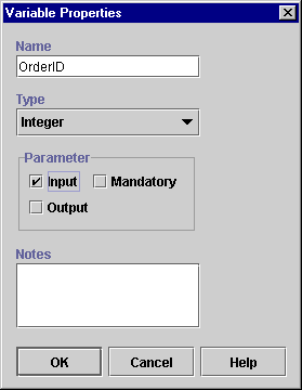
The new variable now appears under the Variables folder in the folder tree.
Figure 4-9 Using the Expression Builder
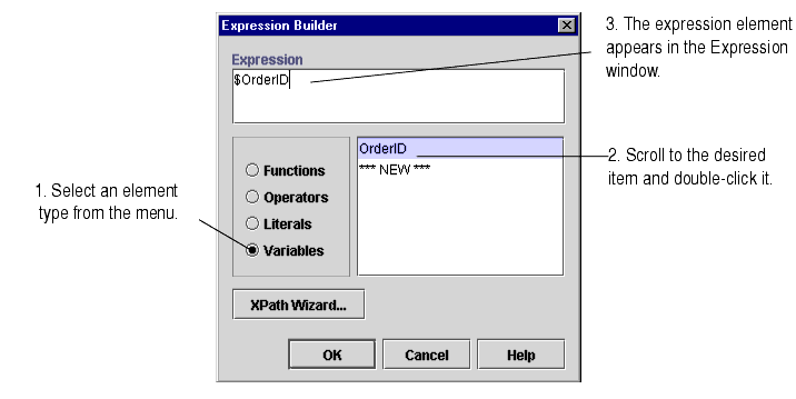
When done, your Expression window should look like the following window.
Activating the Workflow
To make the workflow available to be run, you must activate it.
To activate the Order Processing workflow:
Note: This check box is not available when you first create the template definition, but only after you have opened it.
Figure 4-10 Order Processing Template Definition Dialog Box: Active Check Box
Saving the Workflow
A workflow cannot be run if it has not been saved at least once.
To save the Order Processing workflow, with the template definition open, right-click its folder in the folder tree, and from the pop-up menu, select Save.
In the next section, you will add and define all the variables and actions required by the workflow. Remember to save your workflow periodically as you proceed through the remainder of the tutorial.

|

|

|
|
|
|
Copyright © 2001 BEA Systems, Inc. All rights reserved.
|