Production Operations User Guide
|
|
Configuring a Portal Cluster
This chapter describes the steps necessary to set up a cluster across which your portal application is deployed. The topics discussed in this chapter include:
- Setting up a Production Database
- Reading the wlw-manifest.xml File
- Choosing a Cluster Architecture
- Configuring a Domain
- Understanding Portal Resources
- Zero-Downtime Architectures
Setting up a Production Database
To deploy a portal application into production, it is necessary to set up an Enterprise-quality database instance. PointBase is supported only for the design, development, and verification of applications. It is not supported for production server deployment.
Details on configuring your production database can be found in the Database Administration Guide.
Once you have configured your Enterprise database instance, it is possible to install the required database DDL and DML from the command line as described in the Database Administration Guide. A simpler option, described in this chapter, is to create the DDL and DML from the domain Configuration Wizard when configuring your production environment.
Reading the wlw-manifest.xml File
When configuring your production servers or cluster with the domain Configuration Wizard, you need to deploy JMS queues that are required by WebLogic Workshop-generated components that are deployed at run time. To find the JMS queue names you need, open the wlw-manifest.xml file in the portal application's /META-INF directory.
In the file, find the JMS queue JNDI names that are the defined values in elements named <con:async-request-queue> and <con:async-request-error-queue>. Record the JNDI names of the JMS queues found in those definitions for use when configuring your production system.
You may also need to configure other settings in wlw-manifest.xml. For more information, see How Do I: Deploy a WebLogic Workshop Application to a Production Server?.
Choosing a Cluster Architecture
By clustering a portal application, you can attain high availability and scalability for that application. Use this section to help you choose which cluster configuration you want to use.
Single Cluster
When setting up an environment to support a production instance of a portal application, the most common configuration is to use the WebLogic Recommended Basic Architecture.
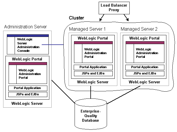
Figure 4-1 shows a WebLogic Portal-specific version of the recommended basic architecture.
Figure 4-1 WebLogic Portal Single Cluster Architecture
Note: WebLogic Portal does not support a split-configuration architecture where EJBs and JSPs are split onto different servers in a cluster. The basic architecture provides significant performance advantages over a split configuration for Portal.
Even if you are running a single server instance in your initial production deployment, this architecture allows you to easily configure new server instances if and when needed.
Multi Cluster
A multi-clustered architecture can be used to support a zero-downtime environment when your portal application needs to be accessible continually. While a portal application can run indefinitely in a single cluster environment, deploying new components to that cluster or server will result in some period of time when the portal is inaccessible. This is due to the fact that while a new EAR application is being deployed to a WebLogic Server, HTTP requests cannot be handled. Redeployment of a portal application also results in the loss of existing sessions.
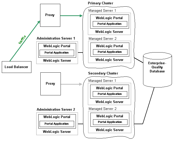
A multi-cluster environment involves setting up two clusters, typically a primary cluster and secondary cluster. During normal operations, all traffic is directed to the primary cluster. When some new components (such as portlets) need to be deployed, the secondary cluster is used to handle requests while the primary is updated. The process for managing and updating a multi-clustered environment is more complex than with a single cluster and is addressed in Zero-Downtime Architectures. If this environment is of interest, you may want to review that section now.
Figure 4-2 Weblogic Portal Multi-Cluster Architecture
Configuring a Domain
You should determine the network layout of your domain before building your domain with the Configuration Wizard. Determine the number of managed servers you will have in your cluster—the machines they will run on, their listen ports, and their DNS addresses. Decide if you will use WebLogic Node Manager to start the servers. For information on Node Manager, see Configuring and Managing WebLogic Server.
WebLogic Portal must be installed on the cluster's administration server machine and on all managed server machines.
Using the Configuration Wizard
Create your new production environment with the domain Configuration Wizard. See Creating WebLogic Configurations Using the Configuration Wizard.
Creating a Production Cluster Environment with the Configuration Wizard
This section guides you through the creation of a production cluster environment for WebLogic Portal.
- Start the Configuration Wizard. In Windows, choose Start > Programs > BEA WebLogic Platform 8.1 > Configuration Wizard.
- In the Create or Extend a Configuration window, select Create a new WebLogic configuration and click Next.
- In the Managed Servers, Clusters, and Machines Options window, select Yes to customize the configuration settings, and click Next.
Note: Do not leave the default "All Local Addresses" setting.
- In the Configure Clusters window, add your cluster(s). Choose a multicast address that is not currently in use. Choose the Cluster addresses for the managed servers in this cluster. These take the form of a comma-separated list of the DNS alias names of the managed servers.
See "Cluster Address" in Using WebLogic Server Clusters for more information.
- In the Assign to Clusters window, choose all the managed servers you want to associate with each cluster by moving the server names from the left pane to the right pane. Click Next.
- In the Configure Machines window, you can create logical representations of the systems that host your server instances. Host information is used for locality routing, especially during session replication. If you are running more than one managed server per machine, it is important that you configure host information so that WebLogic Server does not replicate a session on the same machine.
Also, if you are using Node Manager to manage starting and stopping your servers, you should specify that information here.
- If you choose to Configure Machines, in the Assign Servers to Machines window, target the servers to the appropriate machines.
- In the Configure JDBC Connection Pools window, there will be a cgPool tab. Change the cgPool Vendor to use your production database type, and then specify the information needed to connect to that database instance such as the host and port information.
Make the same changes on the cgJMSPool-nonXA and portalPool tabs.
For cgJMSPool-nonXA, in the Driver field, be sure to select the non-XA driver.
- In the Configure JDBC Data Sources window, you should see a list of JDBC Data Sources configured. Click Next.
- In the Test JDBC Connection Pool and Setup JDBC Database window, select cgPool in the Available JDBC Connection Pools pane, and click Test Connection.
If you have not already created the database objects for the portal application in your database instance, select your database version in the DB Version field, and click Load Database. Warning: Exercise caution when loading the database, as the scripts will delete any portal database objects from the database instance if they already exist. You will see a large number of SQL statements being executed. It is normal for the scripts to have a number of statements with errors on execution, because the script drops objects that may not have been created before.
- In the Configure JMS Connection Factories window, you should see the cgQueue. Its Default delivery mode should be set to Persistent. Click Next.
- In the Configure JMS JDBC Store window, validate that you have JMS stores for the administration server and for each of the managed servers, typically named
cgJMSStore_auto_1,cgJMSStore_auto_2, and so on. - In the Connection Pool field, select the same connection pool used for all stores (such as cgJMSPool-nonXA).
- In the Configure JMS Servers window, validate that you have servers (including the administration server) that correspond to the JMS stores created, typically named cgJMSServer_auto_1, cgJMSServer_auto_2, and so on. To create a JMS server:
- In the Assign JMS Servers to WebLogic Servers window, assign the JMS Servers to the administration server and to each of the managed servers. Click Next.
- In the Configure JMS Distributed Queues window, you need to add new queues that are required by WebLogic Workshop. The JNDI names for these queues can be found in your application's
/META-INF/wlw-manifest.xmlfile, as described in Reading the wlw-manifest.xml File. These names will be similar to
WEB_APP.queue.AsyncDispacherandWEB_APP.queue.AsyncDispacher_error. For each queue, add a new JMS Distributed Queue with the Add button. Set the Name entry and JNDI name entry to the name listed inwlw-manifest.xml. Set the Load balancing policy and Forward delay as appropriate for your application.A pair of queue entries exists for each web application (portal web project) in your portal application. When you are finished, you should have a distributed queue for each queue. In other words, if your Enterprise application has three web applications, you should have added six distributed queues—two for each web application.
You do not need to create queues for the WebLogic Administration Portal web application.
Note: If you are using multiple clusters, create an additional set of queues for each cluster. For example, if you have a web application called basicWebApp, and you are using a second cluster, create a unique basicWebApp queue for that cluster named something like
basicWebApp.queue.AsyncDispatcher.2. When you do this, the Configuration Wizard does not let you enter the same JNDI name for multiple queues. In this example, enter a JNDI name that ends with a ".2". Later in the setup procedures you will make all JNDI names the same in the WebLogic Administration Console for each web application.- In the Assign JMS Distributed Destinations to Servers or Clusters window, target your newly defined queues to your cluster. In the right pane, select the cluster, in the left pane, select the queue(s), and click the right arrow icon. Click Next.
- In the JMS Distributed Queue Members window, click Next. You will create distributed JMS queue members in Setting up JMS Servers.
- In the Target Applications to Servers or Clusters window, target all applications to the administration server as well as to the cluster. Click Next.
- In the Configure Administrative Username and Password window, enter a username and password for starting the administration server. You do not need to configure additional users, groups, and global roles, so make sure No is selected at the bottom of the window. Click Next.
- If you are installing on Windows, in the Configure Windows Options window, select the options you want for adding a shortcut to the Windows menu and installing the administration server as Windows service. The wizard always creates a single default shortcut on the windows menu regardless of what you select for the Create Start Menu option. The option lets you create an additional shortcut with different settings.
If you chose to create a Windows menu shortcut for your domain, click Next in the Build Start Menu Entries window.
For information on starting WebLogic Server, see Creating Startup Scripts.
- In the Configure Server Start Mode and Java SDK window, select Production Mode and select the SDK (JDK) you want to use. Click Next.
Configuring the Administration Server
At this point your administration server domain has been configured using the domain Configuration Wizard. Before you start the administration server to do additional configuration work, you may want to perform one or both of the following setup tasks:
- increase the default memory size allocated to the administration server
- allow server startup without requiring authentication by creating a
boot.propertiesfile
Increasing the Default Memory Size
To increase the default memory size allocated to the administration server, you need to modify your startWebLogic script in the domain's root directory and change the memory arguments. For example:
set MEM_ARGS=-Xms256m %memmax% to set MEM_ARGS=-Xms512m -Xmx512m
MEM_ARGS="-Xms256m ${memmax}" to MEM_ARGS="-Xms512m -Xmx512m"
The exact amount of memory you should allocate to the server will vary based on a number of factors such as the size of your portal application, but in general 512 Mb of memory is recommended as a default.
Allowing Server Startup Without Requiring Authentication
To allow server startup without requiring authentication, create a boot.properties file in your domain root directory that contains the username and password you want to log in with. For example:
username=weblogic
password=weblogic
After the server starts for the first time using this file, the username and password are encrypted in the file.
Setting up JMS Servers
In this procedure you finish configuration of the JMS servers.
- Start the administration server and log in to the WebLogic Server Administration Console, found at
http://server:port/console. - Expand Services > JMS > Distributed Destinations. Perform the following sub-steps for each queue you defined earlier for the WebLogic Workshop components.
- If you are using multiple clusters, change the JNDI names you assigned to the cluster queues in Creating a Production Cluster Environment with the Configuration Wizard step 28. Select each cluster queue (for example, select
basicWebApp.queue.AsyncDispatcher.2), click the General tab, and remove the ".2" suffix (or whatever unique identifier you used in the Configuration Wizard) so that all JNDI names are the same for each web application. For example, all JNDI names for the basicWebApp should bebasicWebApp.queue.AsyncDispatcher. After each change, click Apply. - Create JMS queues and error queues for each web application. Use any name, but for convention you can make the Name the same as the JNDI Name.
View your application's
META-INF/wlw-manifest.xmlfile to see the queues you must create. See Reading the wlw-manifest.xml File.For example, if you have two web applications, basicWebApp and bigWebApp, create the following queues for the administration server JMS server:
basicWebApp.queue.AsyncDispatcher
basicWebApp.queue.AsyncDispatcher_error
bigWebApp.queue.AsyncDispatcher
bigWebApp.queue.AsyncDispatcher_error
You must also create a single queue named
jws.queueif it does not already exist.
Creating Managed Server Directories
Now that you have configured your domain, including defining your managed servers, you need to create a server root directory for each managed server. There are many options for this, depending on whether or not the managed server will reside on the same machine as the administration server and whether or not you will use the Node Manager.
- Most of the files in the domain-level directory are not necessary for managed servers, so a domain (files directly in the domain directory) is not required on each managed server, especially if you are using the Node Manager to start and stop managed servers. For example,
config.xmlin a managed server domain is not used. Instead, theconfig.xmlfile in the administration server is used. The only requirement for managed servers is to have thewsrpKeystore.jksfile one directory above the server directory (in the equivalent of a domain-level directory). - If the managed server will run on a different machine than the administration server and you will not use Node Manager, the easiest option is to use the Configuration Wizard to create a full filesystem domain for the managed server, as described in the following procedure.
WebLogic Portal must be installed on all managed servers.
- In the Configure Administrative Username and Password window, enter a username and password for the server, and click Next.
This information is not typically be used, because you bind this server to the administration server using the administration server's credentials.
- In the Configure Server Start Mode and Java JDK, select Production Mode and the SDK (JDK) you will use with the domain. Click Next.
- In the Create WebLogic Configuration window, choose the directory you want to install to, and in the Configuration Name field, enter a domain name to use. For best practices, choose a domain name like
managedServer1,managedServer2, and so on. - If you want to allow server startup without requiring authentication on each managed server, create a
boot.propertiesfile in each managed server's domain directory (or one level above the server directory) that contains a username and password. For example:
username=weblogic
password=weblogic
Once you have created a filesystem domain directory for a managed server, you can reuse the same domain for your other managed server on the same machine by specifying different servername parameters to your startManagedWebLogic script, or create new managed domains using the domain Configuration Wizard.
Note: If you decide not to use a full domain for your managed servers (that is, not include all files in the domain-level directory), be sure you keep or put a copy of wsrpKeystore.jks in the directory directly above the server directory (in the equivalent of the domain-level directory).
Increasing the Default Memory Size
To increase the default memory size allocated to a managed server (if you are not using Node Manager), you need to modify your startManagedWebLogic script in the managed server root directory and change the memory arguments. For example:
set MEM_ARGS=-Xms256m %memmax% to set MEM_ARGS=-Xms512m -Xmx512m
MEM_ARGS="-Xms256m ${memmax}" to MEM_ARGS="-Xms512m -Xmx512m"
The exact amount of memory you should allocate to the server will vary based on a number of factors such as the size of your portal application, but in general 512 megabytes of memory is recommended as a default.
Understanding Portal Resources
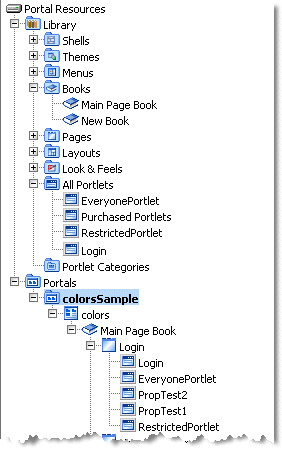
The Portal Library contains books, pages, layouts, portlets, desktops, and other types of portal-specific resources. Using the WebLogic Administration Portal, these resources can be created, modified, entitled, and arranged to shape the portal desktops that end users access.
Figure 4-3 shows an image of the Portal Resources tree in the WebLogic Administration Portal. The tree contains two main nodes: Library and Portals. The Library node contains the global set of portlets and other resources, while the Portals node contains instances of those resources, such as the colorsSample desktop and its pages, books, and portlets.
Figure 4-3 PortAl Resources Library
Each of these resources is defined partially in the portal database so they can be easily modified at run time. The majority of resources that exist are created by an administrator, either from scratch or by creating a new desktop from an existing .portal template file that was created in WebLogic Workshop.
However, portlets themselves are created by developers and exist initially as XML files. In production, any existing .portlet files in a portal application are automatically read into the database so they are available to the WebLogic Administration Portal.
The following section addresses the life cycle and storage mechanisms around portlets, because their deployment process is an important part of portal administration and management.
Understanding the Portlet Deployment Life Cycle
During development time, .portlet files are stored as XML in any existing portal web application in the Portal EAR. As a developer creates new .portlet files, a file poller thread monitors changes and loads the development database with the .portlet information.
In a production environment, .portlet files are loaded when the portal web application that contains them is redeployed on the administration server. This redeployment timing ensures that the content of the portlet, such as a JSP or Page Flow, is available at the same time as the .portlet file is available in the Portal Library. The administration server is the chosen master responsible for updating the database so that there are no issues around every server in the production cluster trying to write the new portlet information into the database at the same time. When deploying new portlets to a production environment, target the portal application for redeployment on the administration server.
Understanding the Database Structure for Storing Portlets
When a portlet is loaded into the database, the portlet XML is parsed and a number of tables are populated with information about the portlet, including PF_PORTLET_DEFINITION, PF_MARKUP_DEFINITION, PF_PORTLET_INSTANCE, PF_PORTLET_PREFERENCE, L10N_RESOURCE, and L10N_INTERSECTION.
PF_PORTLET_DEFINITION is the master record for the portlet and contains rows for properties that are defined for the portlet, such as the definition label, the forkable setting, edit URI, help URI, and so on. The definition label and web application name are the unique identifying records for the portlet. Portlet definitions refer to the rest of the actual XML for the portlet that is stored in PF_MARKUP_DEF.
PF_MARKUP_DEF contains stored tokenized XML for the .portlet file. This means that the .portlet XML is parsed into the database and properties are replaced with tokens. For example, the following code fragment shows a tokenized portlet:
<netuix:portlet $(definitionLabel) $(title) $(renderCacheable) $(cacheExpires)>
These tokens are replaced by values from the master definition table in PF_PORTLET_DEFINITION, or by a customized instance of the portlet stored in PF_PORTLET_INSTANCE.
The following four types of portlet instances are recorded in the database for storing portlet properties:
- Primary - Properties defined in development and stored in the .portlet file.
- Library - Properties defined in the Portal Library, which may be changed using the WebLogic Administration Portal.
- Admin - A customized instance of the portlet in a desktop. This allows you to customize a portlet in a particular way for a desktop without affecting other instances of the portlet in other desktops.
- User - User-customized instances of the portlet defined in the Visitor Tools.
PF_PORTET_INSTANCE contains properties for the portlet for attributes such as DEFAULT_MINIMIZED, TITLE_BAR_ORIENTATION, and PORTLET_LABEL.
If a portlet has portlet preferences defined, those are stored in the PF_PORTLET_PREFERENCE table.
Finally, portlet titles can be internationalized. Those names are stored in the L10N_ RESOURCE table which is linked using L10N_INTERSECTION to PF_PORTLET_DEFINITION.
Removing Portlets from Production
If a portlet is removed from a newly deployed portal application, and it has already been defined in the production database, it is marked as IS_PORTLET_FILE_DELETED in the PF_PORTLET_DEFINITION table. It displays as grayed out in the WebLogic Administration Portal, and user requests for the portlet if it is still contained in a desktop instance return a message that says the portlet is unavailable.
Zero-Downtime Architectures
One limitation of redeploying a portal application to a WebLogic Server cluster is that during redeployment, users cannot access the site. For Enterprise environments where it is not possible to schedule down time to update a portal application with new portlets and other components, a multi-cluster configuration lets you keep your portal application up and running during redeployment.
The basis for a multi-clustered environment is the notion that you have a secondary cluster to which user requests are routed while you update the portal application in your primary cluster.
For normal operations, all traffic is sent to the primary cluster, as shown in Figure 4-4. Traffic is not sent to the secondary cluster under normal conditions because the two clusters cannot use the same session cache. If traffic was being sent to both clusters and one cluster failed, a user in the middle of a session on the failed cluster would be routed to the other cluster, and the user's session cache would be lost.
Figure 4-4 During Normal Operations, Traffic Is Sent to the Primary Cluster
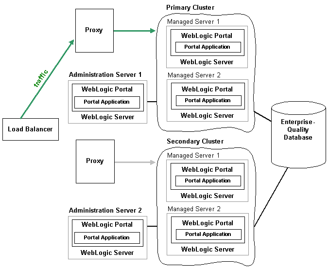
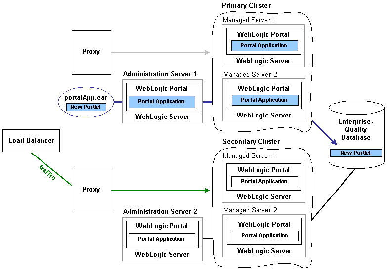
All traffic is routed to the secondary cluster, then the primary cluster is updated with a new Portal EAR, as shown in Figure 4-5. This EAR has a new portlet, which is loaded into the database. Routing requests to the secondary cluster is a gradual process. Existing requess to the primary cluster must first end over a period of time until no more requests exist. At that point, you can update the primary cluster with the new portal application.
Figure 4-5 Traffic Is Routed to the Secondary Cluster; The Primary Cluster Is Updated
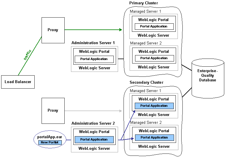
All traffic is routed back to the primary cluster, and the secondary cluster is updated with the new EAR, as shown in Figure 4-6. Because the database was updated when the primary cluster was updated, the database is not updated when the secondary cluster is updated.
Figure 4-6 Traffic Is Routed Back to the Primary Cluster; The Secondary Cluster Is Updated
Even though the secondary cluster does not receive traffic under normal conditions, you must still update it with the current portal application. When you next update the portal application, the secondary cluster temporarily receives requests, and the current application must be available.
In summary, to upgrade a multi-clustered portal environment, you switch traffic away from your primary cluster to a secondary one that is pointed at the same portal database instance. You can then update the primary cluster and switch users back from the secondary. This switch can happen instantaneously, so the site experiences no down time. However, in this situation, any existing user sessions will be lost during the switches.
A more advanced scenario is a gradual switchover, where you switch new sessions to the secondary cluster, and after the primary cluster has no existing user sessions you upgrade it. Gradual switchovers can be managed using a variety of specialized hardware and software load balancers. For both scenarios, there are several general concepts that should be understood before deploying applications, including the portal cache and the impact of using a single database instance.
Single Database Instance
When you configure multiple clusters for your portal application, they will share the same database instance. This database instance stores configuration data for the portal. This can become an issue, because when you upgrade the primary cluster it is common to make changes to portal configuration information in the database. These changes are then picked up by the secondary cluster where users are working.
For example, redeploying a portal application with a new portlet to the primary cluster will add that portlet configuration information to the database. This new portlet will in turn be picked up on the secondary cluster. However, the new content (JSP pages or Page Flows) that is referenced by the portlet is not deployed on the secondary cluster.
Portlets are invoked only when they are part of a desktop, so having them available to the secondary cluster has no immediate effect on the portal that users see. However, adding a new portlet to a desktop with the WebLogic Administration Portal will immediately affect the desktop that users see on the secondary cluster. In this case, that portlet would show up, but the contents of the portlet will not be found.
To handle this situation, you have several options. First, you can delay adding the portlet to any desktop instances until all users are back on the primary cluster. Another option is to entitle the portlet in the library so that it will not be viewable by any users on the secondary cluster. Then add the portlet to the desktop, and once all users have been moved back to the primary cluster, remove or modify that entitlement.
Tip: It is possible to update an existing portlet's content URI to a new location that is not yet deployed. For this reason, exercise caution when updating the content URI of a portlet. The best practice is to update the content URIs as part of a multi-phase update.
When running two portal clusters simultaneoiusly against the same database, you must also consider the portal cache, as described in the next section.
Portal Cache
WebLogic Portal provides facilities for a sophisticated cluster-aware cache. This cache is used by a number of different portal frameworks to cache everything from markup definitions to portlet preferences. Additionally, developers can define their own caches using the portal cache framework. The portal cache is configured in the WebLogic Administration Console under Configuration Settings > Service Administration > Cache Manager. For any cache entry, the cache can be enabled or disabled, a time to live can be set, the cache maximum size can be set, the entire cache can be flushed, or you can invalidate a specific key.
When a portal framework asset that is cached is updated, it will typically write something to the database and automatically invalidate the cache across all machines in the cluster. This process keeps the cache in sync for users on any managed server.
When operating a multi-clustered environment for application redeployment, special care needs to be taken with regard to the cache. The cache invalidation mechanism does not span both clusters, so it is possible to make changes on one cluster that is written to the database but not picked up immediately on the other cluster. Because this situation could lead to system instability, it is recommended that during this user migration window the caches be disabled on both clusters. This is important when you have a gradual switchover between clusters versus a hard switch that drops existing user sessions.
