


|

|
|
| |
How Clusters Work
Overview
The following sections describe how multiple WebLogic Server instances operate with one another to provide services in a clustered configuration. The sections also explain how clients connect to a cluster to make use of clustered services. Understanding these topics is important for planning and configuring a WebLogic Server cluster that meets the needs of your web application.
Server Communication in a Cluster
WebLogic Server instances in a cluster communicate with one another using two basic network technologies:
The ways in which WebLogic Server uses IP Multicast and Socket communication has a direct implication on the way you plan and configure your cluster.
One-to-many communication using IP multicast
IP multicast is a simple broadcast technology that enables multiple applications to "subscribe" to a given IP address and port number and listen for messages. A multicast address is an IP address in the range from 224.0.0.0 to 239.255.255.255.
IP multicast provides a simple method to broadcast messages to applications, but it does not guarantee that messages are actually received. If an application's local multicast buffer is full, new multicast messages cannot be written to the buffer and the application is not notified as to when messages are "dropped." Because of this limitation, WebLogic Servers account for the possibility that they may occasionally miss messages that were broadcast over IP multicast.
WebLogic Server uses IP multicast for all one-to-many communications among server instances in a cluster. This includes:
Implications for cluster planning and configuration
Because multicast controls critical functions related to detecting failures and maintaining the cluster-wide JNDI tree, it is important that neither the cluster configuration nor the basic network topology interfere with multicast communication. Always consider the following rules when configuring or planning a WebLogic Server cluster.
Each cluster requires an exclusive multicast address
A WebLogic Server cluster requires exclusive access to a particular IP multicast address and port number. It is crucial that no other application broadcast or subscribe to the cluster's multicast address. "Sharing" a multicast address with other applications can cause varied problems:
Multicast limits the cluster to a single subnet
Simple IP multicast communication requires that all subscribers to the multicast address reside on the same subnet. For this reason, you cannot distribute members of a WebLogic Server cluster across WAN. WebLogic Server does not support WAN-level multicast tunnelling technologies.
Firewalls can break multicast communication
Although it may be possible to tunnel multicast traffic through a firewall, this practise is not recommended for WebLogic Server clusters. Each WebLogic Server cluster should be treated as a logical unit that provide one or more distinct services to clients of a web application. Such a logical unit should not be split between different security zones. Furthermore, any technologies that can potentially delay or interrupt IP traffic can prove disruptive to a WebLogic Server cluster, generating false failures due to missed heartbeats.
Although it is possible to tune WebLogic Server to account for delayed heartbeats and socket time-outs, doing so reduces the timeliness in which the cluster detects actual failures.
If multicast storms occur
If server instances in a cluster do not process incoming messages on a timely basis, increased network traffic, including NAK messages and heartbeat re-transmissions, can result. The repeated transmission of multicast packets on a network is referred to as a multicast storm, and can stress the network and attached stations, potentially causing end-stations to hang or fail. Increasing the size of the multicast buffers can improve the rate at which announcements are transmitted and received, and prevent multicast storms.
If multicast storms occur because server instances in a cluster are not processing incoming messages on a timely basis, you can increase the size of multicast buffers.
TCP/IP kernel parameters can be configured with the UNIX ndd utility. The udp_max_buf parameter controls the size of send and receive buffers (in bytes) for a UDP socket. The appropriate value for udp_max_buf varies from deployment to deployment. If you are experiencing multicast storms, increase the value of udp_max_buf by 32K, and evaluate the effect of this change.
Do not change udp_max_buf unless necessary. Before changing udp_max_buf, read the Sun warning in the “UDP Parameters with Additional Cautions” section in the “TCP/IP Tunable Parameters” chapter in Solaris Tunable Parameters Reference Manual at http://docs.sun.com.
Peer-to-peer communication using IP sockets
While one-to-many communication among clustered servers takes place using multicast, peer-to-peer communication between WebLogic Server instances uses IP sockets. IP sockets provide a simple, high-performance mechanism for transferring messages and data between two applications. WebLogic Server instances in a cluster may use IP sockets for:
Note: The use of IP sockets in WebLogic Server actually extends beyond the cluster scenario - all RMI communication takes place using sockets, for example, when a remote Java client application accesses a remote object.
Proper socket configuration is crucial to the performance of a WebLogic Server cluster. Two factors determine the efficiency of socket communications in WebLogic Server:
Pure-Java versus native sockets implementations
Although the pure-Java implementation of sockets provides a reliable and portable method of peer-to-peer communication, it does not provide the best performance for heavy-duty socket usage in a WebLogic Server cluster. With pure-Java sockets, socket reader threads must actively poll all opened sockets to determine if they contain data to read. In other words, socket reader threads are always "busy" polling sockets, even if the sockets have no data to read.
This problem is magnified when a server has more open sockets than it has socket reader threads. In this case, each reader thread must poll more than one open socket, waiting for a timeout condition to determine that the socket is inactive. After a timeout, the thread moves to another waiting socket, as shown below.
When the number of opened sockets outnumbers the available socket reader threads, active sockets may go unserviced until an available reader thread polls them.
For best socket performance, always use a native socket implementation, rather than a pure-Java implementation, on the WebLogic Server host. Native socket implementations automatically poll the active sockets and notify WebLogic Server when a socket contains data to read. With native sockets, the socket reader threads do not need to poll inactive sockets - they service only active sockets, and they are immediately notified (via an interrupt) when a given socket becomes active.
To use native sockets with WebLogic Server, set weblogic.system.nativeIO.enable to "true" in the cluster-wide weblogic.properties file. By default, WebLogic Server does not use native sockets. See Performance Packs for more information.
Note: Applets cannot make use of native socket implementations, and therefore have limited efficiency in socket communication. See Using applets with WebLogic for more information.
Configuring reader threads for Java socket implementations
If you do use the pure-Java socket implementation, you can still improve the performance of socket communication by configuring the proper number of socket reader threads. For best performance, the number of socket reader threads in WebLogic Server should equal the potential maximum number of opened sockets. This avoids "sharing" a reader thread with more than one socket, and ensures that socket data is read immediately.
Determining potential socket usage
Each WebLogic Server instance can potentially open a socket for every other server instance in the cluster. However, the actual maximum number of sockets used at a given time is determined by the configuration of your cluster. In practice, clustered systems generally do not open a socket for every other server instance, due to the way in which clustered services are deployed.
For example, if your cluster uses in-memory HTTP session state replication, and you deploy only clustered objects to all WebLogic Server instances, each server potentially opens a maximum of only two sockets, as shown below.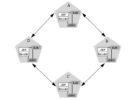
The two sockets in the above example are used to replicate HTTP session states between primary and secondary servers. Sockets are not required for accessing clustered objects, due to the co-location optimizations that WebLogic Server uses. In this configuration, the default socket reader thread configuration is sufficient.
If you pin non-clustered RMI objects to particular servers, the potential maximum number sockets increases, because server instances may need to open sockets to access the pinned object. The figure below shows the affect of deploying a non-clustered RMI object to server A: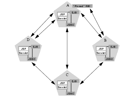
In the above example, each server can potentially open a maximum of three sockets at a given time, to accommodate HTTP session state replication and to access the pinned RMI object on server A.
Additional sockets may be required for servlet clusters in a multi-tier cluster configurations, as described in Recommended Multi-tier Cluster Architecture.
Setting the number of reader threads
By default WebLogic Server creates 3 socket reader threads upon booting. If you determine that your cluster system may utilize more than 3 sockets during peak periods, increase the number of socket reader threads using the weblogic.system.percentSocketReaders property, as described in Performance-related properties. This property is applicable only for Java socket implementations, and you must set it in the cluster-wide weblogic.properties file.
Client communication via sockets
Client applications' use of sockets also affects the way in which you plan a WebLogic Server cluster. When an HTTP or Java client directly connects to a WebLogic Server cluster through a firewall that uses address translation or IP masquerading, it uses only a single socket and the client becomes associated with a single server instance in the cluster.
The basic client connection procedure to a cluster through a firewall is as follows:
This client connection behavior has several ramifications for cluster planning and configuration:
If a client connects directly to a cluster without a firewall, then the client may utilize additional sockets for accessing multiple servers. In this case, you may also want to optimize the socket reader threads that each client uses.
Cluster-wide JNDI naming service
Clients of an individual WebLogic Server access objects and services by using a JNDI-compliant naming service. The JNDI naming service contains a list of the public services that the server offers, organized in a "tree" structure. A WebLogic Server offers a new service by binding into the JNDI tree a name that represents the service. Clients obtain the service by connecting to the server and looking up the bound name of the service.
Server instances in a cluster utilize a cluster-wide JNDI tree. A cluster-wide JNDI tree is similar to a single server JNDI tree, insofar as the tree contains a list of available services. In addition to storing the names of local services, however, the cluster-wide JNDI tree stores replica-aware stubs, which point to services available on multiple servers in the cluster.
Each WebLogic Server instance in a cluster creates and maintains a local copy of the logical cluster-wide JNDI tree. By understanding how the cluster-wide naming tree is maintained, you can better diagnose naming conflicts that may occur in a clustered environment.
Creating the cluster-wide JNDI tree
Each WebLogic Server in a cluster builds and maintains its own local copy of the cluster-wide JNDI tree, which lists the services offered by all members of the cluster. Creating a cluster-wide JNDI tree begins with the local JNDI tree bindings of each server instance. As a server boots (or as new services are dynamically deployed to a running server), the server first binds the names of those services to the local JNDI tree. This local binding process introduces the first level of conflict checking. The service is bound into the JNDI tree only if no other service of the same name exists.
Once the server successfully binds a service into the local JNDI tree, additional steps are taken for clustered objects that use replica-aware stubs. After binding a replica-aware stub into the local JNDI tree, the server broadcasts the availability of the service to other members of the cluster via IP multicast. Other members of the cluster monitor the multicast address to detect when cluster-wide services become available. 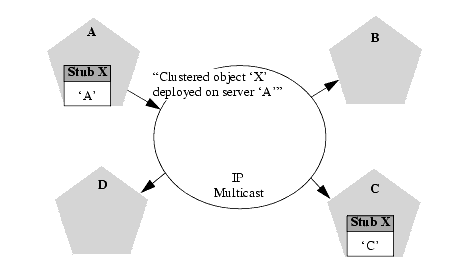
The example above shows a snapshot of the JNDI binding process. Servers A and C have successfully bound the clustered object X into their local JNDI trees. Server A uses multicast to advertise that it has successfully bound the clustered object into it's JNDI tree. (Server C will also broadcast this object's availability, but for this example assume that the message has not yet been sent.)
Other servers in the cluster listening to the multicast address would observe that Server A has successfully bound a cluster-aware service into its JNDI tree. At this point, other servers in the cluster would, in turn, update their local copy of the JNDI tree to indicate that the cluster-aware service is available on Server A.
Updating the local JNDI bindings for replica-aware stubs occurs in one of two ways:
In this manner, each server in the cluster creates its own copy of a cluster-wide JNDI tree. The same process would be used when Server C announces that object X has been bound into its local JNDI tree.
Handling JNDI naming conflicts
Simple JNDI naming conflicts occur when a server attempts to bind a non-clustered service that uses the same name as a non-clustered service already bound in the JNDI tree. Cluster-level JNDI conflicts occur when a server attempts to bind a replica-aware stub that uses the name of a non-clustered object bound in the JNDI tree.
WebLogic Server detects simple naming conflicts (of non-clustered services) when those services are bound to the local JNDI tree. Cluster-level JNDI conflicts may occur when new services are advertised over multicast. For example, if you deploy a pinned RMI object on one server in the cluster, you cannot deploy a replica-aware version of the same object on another server instance.
To avoid cluster-level JNDI conflicts, you should generally deploy all replica-aware objects to all WebLogic Server instances in a cluster (homogeneous deployment). Having unbalanced deployments across WebLogic Server instances increases the chance of JNDI naming conflicts during startup or redeployment. It can also lead to unbalanced processing loads in the cluster.
If you must pin specific RMI objects or EJBs to individual servers, make sure you do not attempt to bind replica-aware stubs using the same object names.
Updating the JNDI tree
If cluster-aware services are removed (undeployed from a server), updates to the JNDI tree are handled similar to the way in which new services are added. The WebLogic Server on which the service was undeployed broadcasts a message indicating that it no longer hosts the service. Again, other servers in the cluster that observe the multicast message update their local copies of the JNDI tree to indicate that the service is no longer available on the server that undeployed the object.
Client interaction with the cluster-wide JNDI tree
Clients that connect to a WebLogic Server cluster and look up a clustered service obtain a replica-aware stub for the service. This stub contains the list of available server instances that host the object. The stub also contains the load balancing logic for distributing the load among its host servers. ( How Object Clustering Works provides more details about replica-aware stubs for EJBs and RMI classes.)
Once the client has obtained a replica-aware stub, the server instances in the cluster may continue adding and removing host servers for the clustered objects, as described in Updating the JNDI tree. This means that a client's replica-aware stub is taken from a "snapshot" of the cluster-wide JNDI tree at a given point in time. The list of servers in the client stub is not refreshed unless:
If your web applications have long-lived clients that require up-to-date versions of replica-aware stubs, you may want to decrease the replicaListRefreshInterval to ensure that client stubs are refreshed more often. (For example, you may want to use a shorter interval if you frequently redeploy clustered objects.) By default, replicaListRefreshInterval is set to 180 seconds. To change it, specify the clusterable and replicaListRefreshInterval options to rmic when you compile an RMI object's stub. See Using WebLogic RMI for more information.
Note: You cannot change the replicaListRefreshInterval for EJBs. EJBs always use the default interval of 180 seconds.
Server Failure Detection
WebLogic Server instances in a cluster detect failures of their peer server instances by monitoring:
Failure detection using IP sockets
WebLogic Servers monitor the use of IP sockets between peer server instances as an immediate method of detecting failures. If a server connects to one of its peers in a cluster and begins transmitting data over a socket, an unexpected closure of that socket causes the peer server to be marked as "failed."
The WebLogic Server "heartbeat"
If clustered server instances do not have opened sockets for peer-to-peer communication, failed servers may also be detected via the WebLogic Server "heartbeat." All server instances in a cluster use multicast to broadcast regular server "heartbeat" messages to other members of the cluster. Each server heartbeat contains data that uniquely identifies the server that sends the message. Servers broadcast their heartbeat messages at regular intervals of 10 seconds. In turn, each server in a cluster monitors the multicast address to ensure that all peer servers' heartbeat messages are being sent.
If a server monitoring the multicast address misses 3 heartbeats from a peer server (i.e. if it does not receive a heartbeat from the server for 30 seconds or longer), the monitoring server marks the peer server as "failed." It then updates its local JNDI tree, if necessary, to indicate that clustered services are no longer provided by the failed server.
In this way, servers can detect failures even if they have no sockets open for peer-to-peer communication.
How Servlet Clustering Works
WebLogic Server supports load balancing and failover services for servlets and JSPs using a replica-aware proxy. The proxy maintains a list of WebLogic Server instances that host a clustered servlet, and forwards HTTP requests to those instances using a simple round-robin strategy. The proxy also provides the logic required locate the replica of a client's HTTP session state if a WebLogic Server instance should fail.
Replica-aware proxies may be installed as plug-ins to third-party web servers, as described below. For WebLogic Server, you can use the HttpClusterServlet to proxy servlet and JSP requests to a WebLogic Server cluster.
Requirements for servlet clustering
To utilize load balancing and failover services for clustered servlets and JSPs, you must configure your WebLogic Server cluster using either the Recommended 2-Tier Cluster Architecture or the Recommended Multi-tier Cluster Architecture described in Planning WebLogic Server Clusters.
Using either of these configurations, you will need to setup one or more web servers that proxy client HTTP requests to a WebLogic Server cluster that hosts the servlets. If you use a third-party web server such as Apache, Netscape Enterprise Server, or Microsoft Internet Information Server, you will need to configure the server to use the WebLogic proxy plug-in, as described in:
If you use WebLogic Servers to provide the HTTP front-end, you must use the HttpClusterServlet to proxy requests to the servlet cluster, as described in Setting Up the WebLogic Server as an HTTP Server.
The proxy plug-ins or HttpClusterServlet must proxy requests for clustered servlets or JSPs to the WebLogic Server cluster, and the servlets and JSPs must use in-memory HTTP session state replication. See Administering WebLogic Clusters for additional configuration information.
Session Requirements
When developing servlets or JSPs that you will deploy in a clustered environment, keep in mind the following requirements.
Session Data Must Be Serializable
In order to support in-memory replication for HTTP session states, all servlet and JSP session data must be serializable. If the servlet or JSP uses a combination of serializable and non-serializable objects, WebLogic Server does not replicate the session state.
Use setAttribute to Change Session State
In an HTTP servlet that implements javax.servlet.http.HttpSession, use HttpSession.setAttribute (which replaces the deprecated putValue) to change attributes in a session object. If you set attributes in a session object with setAttribute, the object and its attributes are replicated in a cluster using in-memory replication. If you use other set methods to change objects within a session, WebLogic Server does not replicate those changes. Every time a change is made to an object that is in the session, setAttribute() should be called to update that object across the cluster. Likewise, use removeAttribute (which, in turn, replaces the deprecated removeValue) to remove an attribute from a session object.
Consider Serialization Overhead for Session Objects
Serializing session data introduces some overhead for replicating the session state. The overhead increases as the size of serialized objects grows. If you plan to create very large objects in the session, first test the performance of your servlets to ensure that performance is acceptable.
Applications Using Frames Must Coordinate Session Access
If you are designing a web application that utilizes multiple frames, keep in mind that there is no synchronization of requests made by frames in a given frameset. For example, it is possible for multiple frames in a frameset to create multiple sessions on behalf of the client application, even though the client should logically create only a single session.
In a clustered environment, poor coordination of frame requests can cause unexpected application behavior. For example, multiple frame requests can "reset" the application's association with a clustered instance, because the proxy plug-in treats each request independently. It is also possible for an application to corrupt session data by modifying the same session attribute via multiple frames in a frameset.
To avoid unexpected application behavior, always use careful planning when accessing session data with frames. You can apply one of the following general rules to avoid common problems:
The following figure depicts a client accessing a servlet hosted in a 2-tier cluster architecture. This example uses a single WebLogic Server to serve static http requests only; all servlet requests are forwarded to the WebLogic Server via the HttpClusterServlet.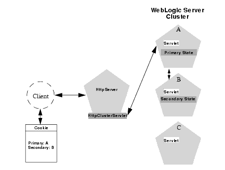
Note: The discussion that follows also applies if you use a 3rd-party web server and proxy-plug, rather than WebLogic Server and the HttpClusterServlet.
When the HTTP client requests the servlet, the HttpClusterServlet proxies the request to the WebLogic Server cluster. The HttpClusterServlet maintains the list of all servers in the cluster, as well as the load balancing logic to use when accessing the cluster. In the above example, the HttpClusterServlet routes the client request to the servlet hosted on WebLogic Server A. WebLogic Server A becomes the primary server hosting the client's servlet session.
To provide failover services for the servlet, the primary server replicates the client's servlet session state to a secondary WebLogic Server in the cluster. This ensures that a replica of the session state exists even if the primary server fails (for example, due to a network failure). In the example above, Server B is selected as the secondary.
The servlet page is returned to the client through the HttpClusterServlet, and the client browser is instructed to write a cookie that lists the primary and secondary locations of the servlet session state. If the client browser does not support cookies, WebLogic Server can use URL re-writing instead; see Using URL re-writing to track session replicas.
Failover procedure
Should the primary server fail, the HttpClusterServlet reads the client's cookie information to determine the location of a secondary WebLogic Server that hosts a replica of the session state. The HttpClusterServlet automatically redirects the servlet requests to the secondary server, and failover is transparent to the client.
After the failure, WebLogic Server B becomes the primary server hosting the servlet session state, and a new secondary is created (server C in the example above). The client browser's cookie is updated to reflect the new primary and secondary servers, to account for the possibility of subsequent failovers.
In a 2-server cluster, the client would transparently failover to the server hosting the secondary session state. However, replication of the client's session state would not continue unless another WebLogic Server became available and joined the cluster. For example, if the original primary server was restarted or reconnected to the network, it would be used to host the secondary session state.
Using URL re-writing to track session replicas
In its default configuration, WebLogic Server uses client-side cookies to keep track of the primary and secondary server that host the client's servlet session state. If client browsers have disabled cookie usage, WebLogic Server can also keep track of primary and secondary servers using URL re-writing. With URL re-writing, both locations of the client session state are embedded into the URLs passed between the client and proxy server. To support this feature, you must ensure that URL re-writing is enabled on the WebLogic Server cluster. See Configuring Session Cookies for more information.
How Object Clustering Works
If an object is clustered, the client has a choice about which instance of the object to call. Each instance of the object is referred to as a replica.
Replica-aware RMI stubs
The key technology that underpins clustered objects in WebLogic Server is the replica-aware stub. When you compile an EJB that supports clustering (as defined in its deployment descriptor) ejbc passes the EJB's interfaces through the rmic compiler to generate replica-aware stubs for the bean. For RMI objects, you generate replica-aware stubs explicitly using command-line options to rmic, as described in WebLogic RMI Compiler.
The replica-aware stub appears to the caller as a normal RMI stub. Instead of representing a single object, however, the stub represents a collection of replicas. The replica-aware stub contains the logic required to locate an EJB or RMI class on any WebLogic Server instance on which the object is deployed. When you deploy a cluster-aware EJB or RMI object, only the stub is bound into the JNDI tree. As described in Cluster-wide JNDI naming service, clustered WebLogic Server instances have the capability to update local copies of the stub so that the stub lists all servers on which the object is available.
The stub also contains the load balancing algorithm (or the call routing class) used to load balance method calls to the object. On each call, the stub employs its load algorithm to choose which replica to call. This provides load-balancing across the cluster in a way that is transparent to the caller. If a failure occurs during the call, the stub intercepts the exception and retries the call on another replica. This provides fail-over that is also transparent to the caller.
Replica-aware EJB stubs
EJBs differ from plain RMI objects in that each EJB can potentially generate two different replica-aware stubs: one for the EJBHome interface and one for the EJBObject interface. This means that EJBs can potentially realize the benefits of load balancing and failover on two levels:
In WebLogic Server 4.5 and 5.1, not all types of EJBs can benefit from load balancing and failover at for method calls. The following sections provide an overview of the capabilities of different EJBs. See EJBs in WebLogic Server Clusters for a detailed explanation of the clustering behavior for different EJB types.
EJB Home stubs
All bean homes are clusterable. When a bean is deployed on a server, its home is bound into the cluster-wide naming service. Because homes are clusterable, each server can bind an instance of the home under the same name. When a client looks up this home, it gets a replica-aware stub that has a reference to the home on each server that deployed the bean. When create() or find() is called, the replica-aware stub routes the call to one of the replicas. The home replica that receives the finds or creates an instance of the bean on its server.
Stateless EJBs
When a home creates a stateless bean, it returns a replica-aware EJBObject stub that can route to any server on which the bean is deployed. Because a stateless bean holds no state on behalf of the client, the stub is free to route any call to any server that hosts the bean. Also, because the bean is clustered, the stub can automatically fail over in the event of a failure. The stub does not automatically treat the bean as idempotent, so it will not recover automatically from all failures. If the bean has been written with idempotent methods, this can be noted in the deployment descriptor and automatic fail-over will be enabled in all cases.
Stateful EJBs
When a home creates a stateful bean, it returns a stub that is pinned to the server hosting the home. Because this bean holds state on behalf of the client, all calls must be routed to the single EJB instance. So in the case of a stateful bean, load-balancing and fail-over only occur during calls to the home. Once the stateful bean has been created, all calls for it must go to the same server. If a failure occurs, the client code must catch the remote exception and retry by creating a new instance using the clustered home.
Entity EJBs
There are two flavors of entity beans to consider: read-write entities and read-only entities.
When a home finds or creates a read-write entity bean, it obtains an instance on the local server and returns a stub pinned to that server. As with a stateful bean, load-balancing and fail-over only occur at the home level. Because it is possible for multiple instances of entity to exist in the cluster, each instance must read from the database before each transaction and write on commit.
When a home finds or creates a read-only entity bean, it returns a replica-aware stub. This stub load-balances on every call and will automatically fail-over in the event of any recoverable call failure. Read-only beans are also cached on every server to avoid database reads.
For more information about using EJBs in a cluster, please read The WebLogic Server EJB Container.
RMI Object stubs
WebLogic RMI provides special extensions for building clustered remote objects. These are the extensions used to build the replica-aware stubs described in the EJB section. For more information about using RMI in WebLogic Server Clusters please read Using WebLogic RMI.
Optimizing for co-located services
Although a replica-aware stub contains the load-balancing logic for a clustered object, WebLogic Server does not always perform load balancing for an object's method calls. In most cases, it is more efficient to use a replica that is co-located with the stub itself, rather than using an replica that resides on a remote server. The figure below details this situation.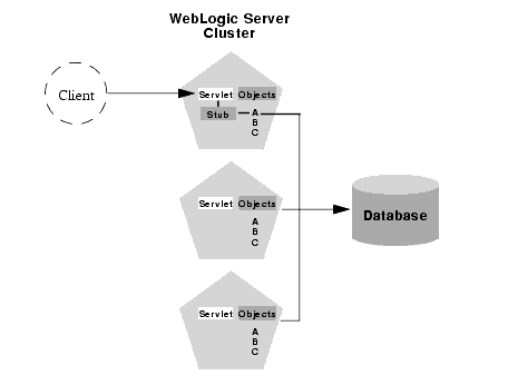
In the above example, a client connects to a servlet hosted by the first WebLogic Server instance in the cluster. In response to client activity, the servlet obtains a replica-aware stub for Object A. Because a replica of Object A is also available on this server, the object is said to be co-located with the client's stub.
WebLogic Server always uses the local, co-located copy of Object A, rather than distributing the client's calls to other replicas of Object A in the cluster. It is more efficient to use the local copy, because doing so avoids the network overhead of establishing peer connections to other servers in the cluster.
This optimization is often overlooked when planning WebLogic Server clusters. The co-location optimization is also frequently confusing for administrators or developers who expect or require load balancing on each method call. In single-cluster web applications, this optimization overrides any load-balancing logic inherent in the replica-aware stub.
If you require load balancing on each method call to a clustered object, see Planning WebLogic Server Clusters for information about how to plan your WebLogic Server accordingly.
Transactional co-location
As an extension to the basic co-location strategy, WebLogic Server also attempts to co-locate clustered objects that are enlisted as part of the same transaction. When a client creates a UserTransaction object WebLogic Server attempts to use object replicas that are co-located with the transaction. This optimization is depicted in the figure below.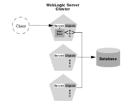
In this example, a client attaches to the second WebLogic Server instance in the cluster and obtains a UserTransaction object. After beginning a new transaction, the client looks up Objects A and B to do the work of the transaction. In this situation WebLogic Server always attempts to use replicas of A and B that are on the same server as the UserTransaction object, regardless of the load balancing strategies for A and B.
This transactional co-location strategy is even more important than the basic optimization described in Optimizing for co-located services. If remote replicas of A and B were used added network overhead would be incurred for the duration of the transaction, because the peer connections for A and B would be locked until the transaction committed. Furthermore, WebLogic Server would need to employ a multi-tiered JDBC connection to commit the transaction, incurring even further network overhead.
By co-locating clustered objects in a transactional context, WebLogic Server reduces the network load both for accessing the individual objects. The server also can make use of a single-tiered JDBC connection, rather than a multi-tiered connection, to do the work of the transaction.

|
|
|
Copyright © 2000 BEA Systems, Inc. All rights reserved.
|