A Understanding the SAP System Role in Remote Processing
The Oracle Application Adapter for SAP R/3 exchanges messages with SAP using three different message type scenarios and two communication roles. Each role has configuration options that must be enabled on the SAP server and on the adapter to enable communications and send messages. This appendix explains the role types, message types, and their related terms. In an SAP Productive system environment, only the proper administrator for a particular configuration role has the authority to change or create the communications entries. This appendix provides a checklist for administrators for the required tasks and describes the entire process of configuring inbound and outbound message processing. This information can be used to configure non-productive systems or for reference purposes.
This appendix contains the following topics:
Functionality of the Adapter
Implementation of the Oracle Application Adapter for SAP R/3 uses the SAP Java Connector (JCo), a Java interface that communicates via Java Native Interface (JNI) to a native c communications layer. The RFC (Remote Function Call) API, implements the CPIC (Common Programming Interface - Communications) and TCP/IP protocols to communicate with a corresponding component on the SAP system. Each message is serialized to or from XML to RFC format, then marshaled into the current SAP message type for transmission to SAP. The SAP server unmarshalls the message into the current runtime object and executes the object. The response message is marshaled into RFC and returned to the adapter for unmarshalling and serialization to XML. This process is seamless and very rapid. Errors can arise from improper credentials, document encoding or actual application errors (for example, a wrong value for a given field).
Roles
The RFC protocol is a dynamic protocol depending on the mode of the request. When a request is inbound to a RFC connected node, the function of that node is a server to fill the request. When a request is outbound from a node, the function of that node is a client, waiting for a server to respond to the request. Outbound events, which need no response, are also processed by servers.
Client
The system instantiating a connection to another system is a client, and the client role processes request/response messages in a synchronous manner. A client system does not execute, but enables message processing. Messages begin and end on the client. The adapter functions as a client when it sends messages from Oracle to SAP.
Types of client connections include:
-
Application Server, which connects to a single SAP application server.
-
Message Server, which connects to an SAP logon load balancer message server for connection to a group of SAP application servers for distributed load processing.
Both connection types use a special type of connection called a Connection Pool, which is discussed later in this appendix.
Types of client message types include:
-
BAPI messages, which are object-style messages with parameters as XML attributes.
-
RFC messages, which are RFC-style messages with parameters as XML elements.
-
Intermediate Documents (IDocs), which use the ALE message system to send positional delimited flat text or XML element parameters.
Server
The system receiving a connection request from another system is a server. A server executes message processing and returns results to a client. A server can reject a message request if it does not implement the processing for a given message with an exception for NOT_IMPLEMENTED. A server can process two types of messages:
-
Inbound messages, which contain the message request and the parameters for the request.
-
Synchronous messages, which take the inbound message request and either perform additional work, pass it to another system, or process it for additional processing before returning it to SAP.
The SAP application server waits for a synchronous message process to finish before continuing.
Types of server connections include:
-
Processing Mode (Request), a simple receipt of message type and parameters.
-
Response, which executes a synchronous process.
Types of server message types include:
-
RFC messages, which are RPC-style messages with parameters as elements.
-
Intermediate Documents (IDocs), which use the ALE message system to send positional delimited flat text or XML element parameters.
SAP Inbound Message Processing
Sending request / response (client) messages to an SAP system for Remote Function Call (RFC) or Business Application Interface (BAPI) objects requires a valid set of logon credentials. For more information on how to configure adapter targets, including the list of required parameters, see "Identifying SAP R/3 Logon Parameters". For the valid values for the adapter target, see your SAP system administrator.
Obtain the following values before initial logon:
-
Valid SAP connection parameters.
-
SAP Communications user (a SAP GUI DIALOG user is not recommended for security reasons).
-
The correct SAP authorizations for the tasks the adapter is expected to perform.
The proper SAP authorizations must be obtained before connecting to the server. It is a recommended SAP security practice to not allow RFC and DIAG access to the same user ID.
The basic authorization object used to secure RFC access is:
S_RFC: Secures the Function Group (located in authorization object class AAAB).
-
Authorization Object+S_RFC:
-
Authorization Field:RFC_TYPE
-
Authorization Value: "FUGR' is the only valid value.
-
Authorization Field: RFC_NAME
-
Authorization Value: The name of an activated function group. For example: ("ABCD") or '*'.
-
Authorization Field: ACTVT
-
Authorization Value: 16 (Execute) is the only valid value.
-
Individual function modules may have additional security inside their executable code. It is the requirement of the function developer or application creator to inform the users of the function or application of the authorization requirements to use the function or application. Consult the administrator to determine if there are additional authorizations required.
Individual tables may be secured from access by using the following authorization object:
S_TABU_DIS: Secures tables (located in authorization object class BC_A)
-
Authorization Object+S_TABU_DIS:
-
Authorization Field: DICBERCLS: Or ("Authorization Group").
-
Authorization Value: For example, Table: MARA is in group “MA”.
-
Authorization Field: ACTVT
-
Authorization Value: 03 (Display)
For a complete explanation on using this authorization object, see the SAP system documentation.
-
Once the correct credentials are specified for the adapter target and the correct authorizations are assembled on the SAP application system, the adapter is ready to be initialized.
Request / Response (Client) Messages
Business Object Repository
Use Application Explorer to expand the appropriate application tree branch, such as Financial Accounting, and then navigate to and expand a Business Object, such as Company Code. Click the object to view the methods of that object. BAPIs have release and versioning. All BAPIs used at runtime must be in "release" status or a runtime exception is generated. Select a method to generate the XML schema. Create an XML instance document from the XML schema and populate it with data. Create an Oracle process with an appropriate input and output (file/html/etc) transmission method. Submit the document to the adapter for processing to receive a result.
Remote Function Call
Use Application Explorer to expand the appropriate application tree branch such as Financial Accounting and then navigate to and expand a Function Group, such as 0002 - Company Code. Each function exposes a different method of processing. All BAPIs are present as RFC objects because their implementation is via RFC. They can be called in this manner allowing for event processing, for example, when BAPI processing does not. Not all RFCs are present as BAPIs. Select a function and generate the XML schema. Create an XML instance document from the XML schema and populate it with data. Create an Oracle process with an appropriate input and output (file/html/etc) transmission method. Submit the document to the adapter for processing to receive a result.
ALE IDOC Message
SAP ERP ALE* Inbound Message processing, where IDocs are sent and stored in the SAP R/3 system, requires some configuration on the SAP server to be used. In this role, messages are sent to SAP as transactional data and stored on the SAP server. The document data is processed in a second step inside SAP, during a triggered workflow.
Configuring SAP R/3 Inbound Processing
Sending an IDoc to SAP ERP requires the following information about the message parties:
-
Sender of the message
-
Receiver of the message
-
Type of message that is being sent
The Sender and Receiver must be defined in the ALE system, and for each party, what kind of message each party is accepting and how it is being processed.
The Sending and Receiving system information are defined in units called Logical Systems, because the connection information does not involve physical connection information. A Logical System acts as a container for all the information about a particular Sender or Receiver.
Once a Logical System is defined, information about the different messages it sends and receives is stored in a Distribution Model. This model must be defined before any processing can occur, and it must be defined precisely to avoid Sender or Receiver errors. In the Distribution Model, the IDoc Message Application may also enable filters, which allow only specific parts of the IDoc to be sent, or distributed. There is a one-to-one correspondence between Logical System, Distribution Model, and Message Type. Complex filter rules can be configured by filter groups, filter objects, rules, and dependencies. For a complete explanation on configuring distribution models with filters, see the SAP system documentation.
Processing an IDoc by the SAP system is defined in Partner Profiles. For each partner and message, it is possible to define process codes to (possibly) process messages differently.
For sending messages to SAP, an ALE administrator must assign (after logon credentials):
-
Logical System name.
-
Message Types and IDoc Basic Types to be transmitted to the SAP application server.
Inside the SAP ERP system, the ALE Administrator must:
-
Create the Logical System.
-
Create the Distribution Model.
-
Assign the Sender for the model.
-
Assign the Receiver for the model.
-
Assign the Message Types.
-
-
Create a Partner Profile for the Logical System.
-
For each message type, assign a process code for SAP to process the message.
-
-
Logical System "ORACLIENT" is created (via SAP transaction SALE).
-
Distribution Model "ZORACLNT" is created (via SAP transaction BD64).
-
Message Type "MATMAS" is added for sending partner "ORACLIENT" and receiving partner "T90ALECNT" (ALE component of central host).
-
Partner Profile "ORACLIENT" is created (via SAP transaction WE20) and Inbound Message "MATMAS" is assigned with Process code "MATM".
Note:
The steps for configuring SAP ERP for inbound messages are described here as a reference. For more comprehensive information, see the SAP ERP documentation.You must perform the following steps to configure SAP R/3 for inbound IDoc processing:
-
Configure a Logical System.
-
Configure a Distribution Model.
-
Define an inbound Partner Profile.
Configuring a Logical System
A Logical System is the container object for configuration information about the Sender or Receiver party of a message. It is a Logical System because no connection information is stored, only information about the message that the end point is able to process and the method used to process the message(s).
-
/n - Ends the current transaction and opens a new one immediately.
-
/o - Keeps the current transaction context and opens a new transaction in a new window.
A Logical System definition is created by creating an entry in the SAP Implementation Guide for Customizing (IMG).
ALE is the SAP ERP Application Link Enablement system, so use the /nSALE transaction to navigate to the IMG for ALE.
-
Navigate to the SALE transaction, as shown in Figure A-1.
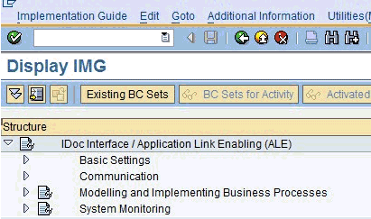
The Display IMG window displays the ALE configuration tree, as shown in Figure A-2.
-
Perform the following steps:
-
Expand the Basic Settings node.
-
Expand Logical Systems.
-
Click Define Logical System.
-
Since SAP R/3 users may see a slightly different screen, expand the extra node, Sending and Receiving Systems.
The "Caution: The table is cross-client" message is displayed, as shown in Figure A-3.
This message appears to inform you that changes to customizing data in Logical Systems applies to all users of the SAP ERP server. This is in contrast to most application data, which is specifically bound to a logon client. Do not make any changes to Logical System entries. Only add the new information. Use an SAP logon ID with the correct privileges to do so.
-
-
Click the green check mark to continue.
The Change View "Logical Systems" window is displayed, as shown in Figure A-4.
Figure A-4 Change View "Logical Systems" Window
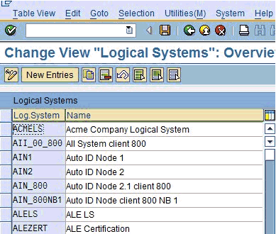
Description of "Figure A-4 Change View "Logical Systems" Window"
-
Click the New Entries button.
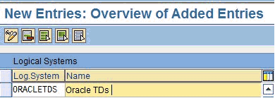
The New Entries: Overview of Added Entries window is displayed, as shown in Figure A-5.
Figure A-5 New Entries: Overview of Added Entries Window
Description of "Figure A-5 New Entries: Overview of Added Entries Window"
-
Enter the Logical System (for example, ORACLETDS) in the Log.System column and provide a description in the Name column.
Note:
The fields are highlighted in yellow to remind you that they are required fields. -
Click the Save icon on the top menu bar, as shown in Figure A-6.
The Prompt for Workbench request dialog is displayed.
Note:
Depending on system usage, the last workbench request number appears in the dialog. Do not use it and proceed to the next step. -
Click the New Request icon to create a new request, as shown in Figure A-7.
-
Enter the description for your entry in the request system. The remaining fields are filled in automatically and do not need to be changed.
The Prompt for Workbench Request dialog is displayed again, with the new request number filled in with the last request number created in the Workbench; do not use it. Click the check mark to create a new request number, as shown in Figure A-8.
Figure A-8 Prompt for Workbench Request Dialog

Description of "Figure A-8 Prompt for Workbench Request Dialog"
The Logical System Entries window refreshes with the new Logical System information. The new Logical System is highlighted in blue to indicate the successful completion of this step, as shown in Figure A-9.
Configuring a Distribution Model for a Logical System
A Distribution Model contains a Sender Logical System and a Receiver Logical System the type of Messages sent and received. If a given Sender or Receiver does not have a valid Distribution Model, then the message is processed and routed to an error location. For advanced topics in Distribution Model, including SAP BAPI Objects and filtering, see the SAP documentation.
To define a distribution model:
-
Run the bd64 transaction, as shown in Figure A-10.
The Display Distribution Model window is displayed in the default Display mode, which shows the current model view entries, as shown in Figure A-11.
-
Expand the tree to view the entries for each model view.
To add items, the transaction must be switched into "change mode".
-
Click Distribution model and select Switch processing mode, as shown in Figure A-12.
Figure A-12 Switch Processing Mode Option

Description of "Figure A-12 Switch Processing Mode Option"
The screen refreshes and the model view window is switched to Change Distribution Model, as shown in Figure A-13.
-
From the available menu buttons, select Create Model View.
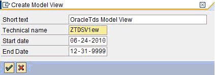
The Create Model View dialog is displayed, as shown in Figure A-14.
-
Enter a Model View name in the Short text field and a name in the Technical name field, which also serves as a description.
A good convention is to use names starting with the letter Z, since SAP does not overwrite these names in case of system updates. This is only the name of the Model View.
-
Click the green check mark icon to enter the information.
The screen refreshes and returns to the main Change Distribution Model window. The Distribution Model configured is now added to the list, as shown in Figure A-15.
Figure A-15 Change Distribution Model Window

Description of "Figure A-15 Change Distribution Model Window"
The Model View is in temporary transaction storage (and the entry appears in lighter color) until you click the Save icon. If the system connection is lost or times out, then the entry is lost. As a best practice, save your changes after each dialog during the Distribution Model configuration process to avoid losing changes.
-
Place the cursor on the entry previously defined.
The entry is now highlighted, as shown in Figure A-16.
-
In the middle menu bar, click the Add Message Type button.
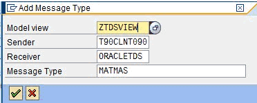
The Add Message Type dialog is displayed.
-
Perform the following steps:
-
In the Sender field, enter the name of the sending Logical System for the Oracle system (for example, ORACLETDS). For more information, see "Configuring a Logical System".
-
In the Receiver field, enter the name of the Client ALE Logical System for the SAP system (ALE receiver), or select from the drop-down (for example, T90CLNT090).
-
In the Message type field, enter the message type you want to use (for example, MATMAS).
You can click the drop-down icon to the right of each field to browse available values from a list.
-
Click the green check mark icon to enter the information.
The main Change Distribution Model window refreshes.
-
-
Click Save.
-
Navigate the ALE Hierarchy tree to the Distribution Model recently created. The Sender and Receiver are depicted in a graphical relationship with Sender, Receiver, and Message, as shown in Figure A-17.
Figure A-17 Sender, Receiver, and Message Components

Description of "Figure A-17 Sender, Receiver, and Message Components"
For subsequent message types for the same systems, expand the Model View to the receiver name and place the cursor on the name. Then click the Add Message Type button. All the fields are populated automatically. You can then add the message type.
Defining a Partner Profile
A Partner Profile defines for each logical system, the messages processed, and how the message is processed. This allows for flexible configuration of processing details for partners. Each message type may have only one entry in a Partner Profile. To define a Partner Profile:
-
Run the we20 transaction, as shown in Figure A-18.
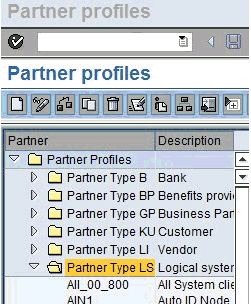
The Partner profiles window is displayed, as shown in Figure A-19.
-
Select Partner Type LS and click the white icon on the middle menu bar. You can also select Create from the top menu.
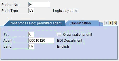
The right side of the screen changes to a blank Partner Profile form, as shown in Figure A-20.
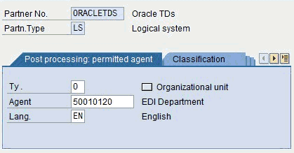
-
Enter the name of the Logical System (for example, ORACLETDS) in the partner number field and click the Save icon.
The screen changes with the new profile, as shown in Figure A-21.
-
Scroll down until the embedded text "Inbound parmtrs" entry is displayed.
-
Click the green plus sign icon.
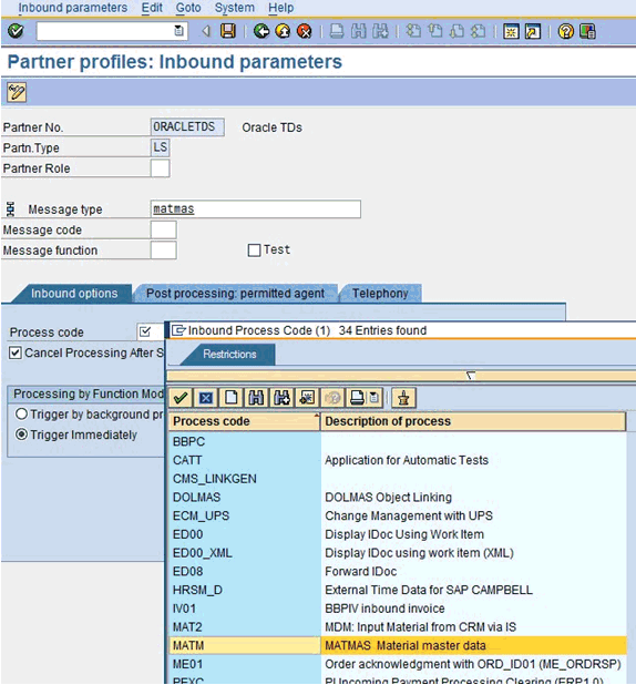
The Partner profiles: Inbound parameters dialog is displayed, as shown in Figure A-22.
Figure A-22 Partner Profiles: Inbound Parameters Dialog
Description of "Figure A-22 Partner Profiles: Inbound Parameters Dialog"
-
Enter MATMAS as the Message Type.
-
Use the Process code drop down to find and select MATM for MATMAS.
-
Select Immediate or Background as the Process Mode.
Note:
Consult your SAP administrator for the proper settings. -
Click the Save icon on the menu bar to save the Inbound Partner Profile entry for MATMAS.
-
Click the Back button on the menu bar to return to the previous window, as shown in Figure A-23.
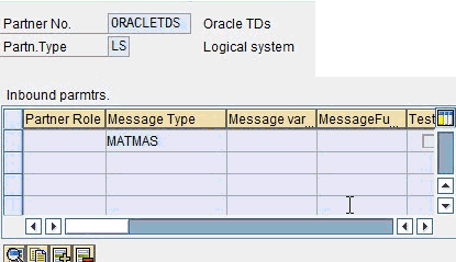
MATMAS is displayed in the entry list, as shown in Figure A-24.
This completes the inbound configuration for Logical System/Partner Profile: OracleTDS/MATMAS. To add additional inbound IDoc Message Type entries, repeat the steps beginning with "Configuring a Distribution Model for a Logical System". To add another Logical System and Message Type, repeat the steps from "Configuring a Logical System".
You can now begin sending IDocs after configuring the appropriate Oracle process.
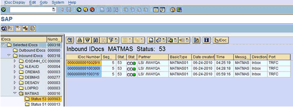
From the SAP IDoc monitor console, you can monitor the IDoc transactions in SAP transaction WE02. The processing state and status of IDocs are available, as well as the Sender, Receiver, and the data, as shown in Figure A-25.
SAP Outbound Message Processing
The Oracle Application Adapter for SAP R/3 can process two types of outbound from SAP application server messages, Remote Function Call messages or Transactional RFC messages with transaction ID. All communications processing via the SAP JCO is synchronous (request /response), but message processing can either be asynchronous (delivery only) or synchronous (an orchestrated process performs work and returns information to waiting SAP application server). RFC messages can be sent from SAP ABAP programs or the SAP workflow system or even the SAP function test transaction.
Outbound processing often is implemented as Events. On the SAP application server, there are many stages of defined events. Event processing is held together by linkages. Not all linkages are enabled by default on a Productive SAP server. For an Event to be active, and capable of sending messages, there must be an object capable of sending changes in the status of the object, a link to list of valid events, and event handlers. An event handler implements the processing of the message.
Active SAP Events are status changes on defined components with implemented event handlers. There are many types of events in the SAP application server, the most well known event handler is ALE Message Control, implemented by SAP around objects like the Material Master and Customer Master. Changes in these objects can generate outbound event IDocs.
Event creation is usually implemented by SAP, but many objects can be enabled for event handling, but this often requires advanced configuration or programming. Consult the SAP documentation for information on the type of SAP events and how they are configured.
For RFC outbound messages, only a SAP RFC Destination and Program ID are needed to receive the Remote Function Call.
For IDoc processing, a Logical System, Distribution Model, Partner Profile and Port must be created to receive message control events via tRFC.
SAP Outbound Terminology
-
JCO/RFC Client, which is the system making the RFC request, and optionally waiting for a response.
-
JCO/ RFC Server, which is the system receiving the RFC request, handling the request, and optionally receiving a response.
SAP Gateway
The SAP Gateway is a process that runs on an SAP application server or a dedicated gateway server. The gateway process manages all connections to SAP. No server connections to SAP are accepted unless they are configured previously as registered programs in the SAP application and present the required program identifier.
A server connection presents itself to the Gateway and exposes a Program Identifier. If the Program Identifier is found in the list of registered Program IDs, then the Gateway server offers a connection to the server, which "accepts" a connection. This ProgramID is then linked with an RFC Destination within SAP, which enables SAP Function Modules and ALE documents (IDocs or BAPI IDocs) to be routed to the destination. The RFC Destination functions as a key to identify the SAP Program ID. The Program ID is also exposed by the application server making the connection to SAP and is the direct link to the IP address of the connecting server. Messages are routed to the application server via the RFC Destination. A good security practice is to separate Oracle Application Adapter for SAP R/3 users with access to the adapter instance implementing the Program id and the users with SAP transaction authority to change or view the Program ID inside SAP, all requests are routed through the RFC Destination.
Note:
An RFC server program is registered with the SAP gateway and waits for incoming RFC call requests. An RFC server program registers itself under a Program ID at a SAP Gateway and not for a specific SAP system. In SAPGUI, the destination must be defined with transaction SM59, using connection type T and Register Mode. Moreover, this entry must contain information on the SAP gateway at which the RFC server program is registered.Program IDs and Load Balancing
If the Gateway Server has a connection to a particular server instance and another server instance presents itself to the gateway, then the gateway offers the connection and then begins functioning in Load Balancing mode. Using a proprietary algorithm, the Gateway sends different messages to each server depending on demand and total processing time. This may cause unpredictable results when messages are validated by schema and application.
When configuring multiple events in the Oracle using a single SAP program ID, SAP load balances the event data. For example, if multiple remote function calls or BAPIs use the same program ID (for example, ORACLETDS) and multiple SAP listeners are configured with this progamID, then SAP sends one request to one listener and the next to another listener, and so on. There is a load-balancing algorithm present in the SAP Gateway Server. This mechanism is proprietary to SAP application development and might work by comparing total throughput of the connection, the number of times in wait state, and so on. One connection might receive nine messages and a second connection might receive one message. If five of the nine messages are rejected for schema validation and the one message on the other connection is rejected for schema validation, then you might suspect that you are missing SAP event handling messages.
Load balancing in server (inbound to adapter from SAP) situations is handled by connecting multiple instances of the adapter to the SAP system. The SAP system then load balances the connections. You cannot tune this performance.
-
Create a RFC Destination (via SM59).
-
Enter a Destination Name.
-
Enter a Registered Program ID.
-
In the MDMP & Unicode tab, ensure that the Unicode option is selected.
-
Start Oracle BPEL/Mediator.
-
Enter the same registered Program ID value from step b for the BPEL or Mediator channel.
-
Start the channel.
-
Test the connection using the Test button in SAP.
-
-
Simulate a SAP RFC message (via SE37).
ABAP Workbench authorization is required.
-
Enter the RFC Destination name from step 1a in the Destination field.
-
Enter a valid SAP RFC Function name in the Function field.
-
Enter data in the parameters for the function.
-
Click the Execute (clock) button.
Data arrives at the BPEL channel.
-
Before IDocs can be received from SAP, a channel for the Oracle Application Adapter for SAP R/3 must be configured using Application Explorer. In addition, configuration on the SAP application server is also required.
-
Create a RFC Destination (via SM59) or use the same destination defined in the previous section (SAP RFC Outbound Outline).
-
Enter a Destination Name.
-
Enter a Registered Program ID.
-
In the MDMP & Unicode tab, ensure that the Unicode option is selected.
-
Start Oracle BPEL/Mediator.
-
Enter the same Registered Program ID value from step b for the BPEL or Mediator channel.
-
Start the channel.
-
Test the connection using the Test button in SAP.
-
-
Create or use a Logical System as described in "Configuring a Logical System".
-
Define or use a Distribution Model as described in "Configuring a Distribution Model for a Logical System".
-
Create an SAP Transactional RFC Port via transaction WE21.
-
Create an SAP Outbound Partner Profile via transaction WE20.
Registering a RFC Destination and Program ID in SAP GUI
To enable your SAP R/3 system to issue the following calls or interfaces to the SAP R/3 event adapter, you must register your program ID under an RFC destination.
-
Remote Function Calls (RFC)
-
Business Application Programming Interfaces (BAPI) - Bapis have no external events, use the RFC form
-
Intermediate Documents (IDocs)
The RFC Destination is a symbolic name (for example, ORACLETDS) that is used to direct events to a target system, masking the Program ID. The Program ID is configured in SAP GUI and the event adapter.
To register a Program ID:
-
Launch the SAP GUI and log in to the SAP R/3 system.
-
Select Tools, Administration, Network, and then RFC destination.
-
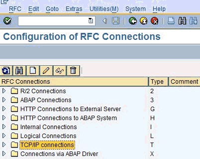
Run the SM59 transaction.
The Configuration of RFC Connections window is displayed, as shown in Figure A-26.
Figure A-26 Configuration of RFC Connections Window
Description of "Figure A-26 Configuration of RFC Connections Window"
-
Select TCP/IP connections and click Create (white paper icon).
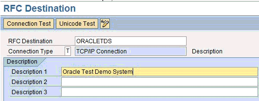
The RFC Destination window is displayed, as shown in Figure A-27.
-
Provide the following information:
-
In the RFC destination field, enter a name, for example, ORACLETDS.
This field value is case-sensitive. Match the same case in the sending programs.
-
In the Connection type field, enter T for destination type TCP/IP.
-
In the Description field, enter a brief description.
-
-
Click the Save icon (Disk) from the tool bar or select Connection, Save from the top menu bar.
The window refreshes and the Technical Settings tab is highlighted in the second panel.
-
Immediately click the Registered Server Program button.
The screen refreshes again.
-
Enter the case sensitive Program Id, this must match the same name in the adapter channel
-
Click the Save icon (Disk) from the tool bar or select Connection, Save from the top menu bar.
-
Select the MDMP & Unicode tab and click the Unicode button.
-
Click the Save icon (Disk) from the tool bar or select Connection, Save from the top menu bar.
The RFC Destination and Program ID are now defined. Any Remote Function Call (RFC) can now be sent to the server via the Destination parameter of the Call Function API. The data for the function must be marshaled and sent to the adapter as this is a reverse invocation.
To test the configuration:
-
Enter the Program ID in the BPEL process / channel for Oracle Application Adapter for SAP R/3 and start the channel.
-
Enter SAP GUI and navigate to SE37.
ABAP Workbench authorization is required.
-
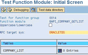
Enter a valid function name and click the Test Run (tool) icon, as shown in Figure A-28.
The Test Function Module: Initial Screen window is displayed, as shown in Figure A-29.
Figure A-29 Test Function Module: Initial Screen Window
Description of "Figure A-29 Test Function Module: Initial Screen Window"
-
Enter the name of the RFC Destination, any data, and then click the Execute (clock) icon.
Since this is reverse invocation, all data must be passed to the function for sending to the adapter. After a success, the execution time is displayed, as shown in Figure A-30. The first run is always the longest, subsequent runs are faster.
Synchronous RFC calls are defined in the same way as asynchronous on the SAP side. On the adapter side, ensure "request_response" is selected as the mode for the call. Orchestrate a process that takes the SAP delivered data, processes it, and returns it to SAP in the function format. Any format errors immediately terminate the request. Example (in pseudo code):
Function: MY_COMPANY_GETLIST DESTINATION 'ORACLETDS'
tables mycompanies field1: name(20) field2: company(20)
The synchronous Get List call passes the empty table mycompanies to BPEL server and SAP waits. BPEL orchestration includes an object that has the following SQL statement:
select name(20), company(20) into mycompanies where country eq us
The SQL statement is executed on an Oracle database and the result set is returned and passed into the mycompanies table by an assignment statement in the orchestration. Remember that the SAP application is waiting during the entire process, and that the SAP server may have a maximum online process time at which the process is automatically terminated by SAP.
The function returns to SAP via synchronous call and the table is returned with data to the calling process.
Time outs can occur if the execution time is longer than the connection pool execution time. Format exceptions can occur for type, length, or decimal places.
Application Link Embedding Configuration for the Event Adapter
The SAP R/3 event adapter receives IDocs (Intermediate Documents) from SAP R/3. To configure an SAP R/3 system to send IDocs to the SAP R/3 event adapter, use the ALE (Application Link Embedding) configuration to:
-
Register your program ID in SAP GUI.
-
Define a Port.
-
Create a Logical System.
-
Create a Partner Profile.
-
Create a Distribution Model for the Partner and Message Type.
-
Test the SAP R/3 event adapter.
Defining a Port
A Port identifies where to send messages. The Port type used by Oracle Application Adapter for SAP R/3 is the Transactional RFC port. By defining an ALE port and linking it to the RFC Destination, this creates the message execution process pathway.
To define a port:
-
In the ALE configuration, select Tools, Business Communications, IDocs Basis, IDoc, and then Port Definition.
You can also run the WE21 transaction.
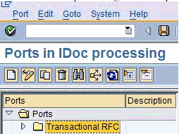
The Ports in IDoc processing window is displayed, as shown in Figure A-31.
Figure A-31 Ports in IDoc Processing Window
Description of "Figure A-31 Ports in IDoc Processing Window"
-
In the left pane under Ports, select Transactional RFC and click Create (white paper icon).
-
Click Generate port name.
The system generates the port name.
-
Enter the version of the IDocs to send through this port (usually 4).
-
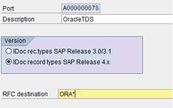
Type or select the name of the RFC Destination created (for example, ORACLETDS) or enter the first letters and an asterisk for the select list, as shown in Figure A-32.
-
Save the session, making note of the generated RFC port.
Configuring a Logical System
Note:
You can skip this section if you are reusing a Logical System that has been previously defined.A Logical System is the container object for configuration information about the Sender or Receiver party of a message. It is a Logical System because no connection information is stored, only information about the message that the end point is able to process and the method used to process the message(s).
-
/n - Ends the current transaction and opens a new one immediately.
-
/o - Keeps the current transaction context and opens a new transaction in a new window.
A Logical System definition is created by creating an entry in the SAP Implementation Guide for Customizing (IMG).
ALE is the SAP ERP Application Link Enablement system, so use the /nSALE transaction to navigate to the IMG for ALE.
-
Navigate to the SALE transaction, as shown in Figure A-33.
The Display IMG window displays the ALE configuration tree, as shown in Figure A-34.
-
Perform the following steps:
-
Expand the Basic Settings node.
-
Expand Logical Systems.
-
Click Define Logical System.
-
Since SAP R/3 users may see a slightly different screen, expand the extra node, Sending and Receiving Systems.
The "Caution: The table is cross-client" message is displayed, as shown in Figure A-35.
This message appears to inform you that changes to customizing data in Logical Systems applies to all users of the SAP ERP server. This is in contrast to most application data, which is specifically bound to a logon client. Do not make any changes to Logical System entries. Only add the new information. Use an SAP logon ID with the correct privileges to do so.
-
-
Click the green check mark to continue.
The Change View "Logical Systems" window is displayed, as shown in Figure A-36.
Figure A-36 Change View "Logical Systems" Window

Description of "Figure A-36 Change View "Logical Systems" Window"
-
Click the New Entries button.
The New Entries: Overview of Added Entries window is displayed, as shown in Figure A-37.
Figure A-37 New Entries: Overview of Added Entries Window

Description of "Figure A-37 New Entries: Overview of Added Entries Window"
-
Enter the Logical System (for example, ORACLETDS) in the Log.System column and provide a description in the Name column.
Note:
The fields are highlighted in yellow to remind you that they are required fields. -
Click the Save icon on the top menu bar, as shown in Figure A-38.
The Prompt for Workbench request dialog is displayed.
Note:
Depending on system usage, the last workbench request number appears in the dialog. Do not use it and proceed to the next step. -
Click the New Request icon to create a new request, as shown in Figure A-39.
-
Enter the description for your entry in the request system. The remaining fields are filled in automatically and do not need to be changed.
The Prompt for Workbench Request dialog is displayed again, with the new request number filled in with the last request number created in the Workbench; do not use it. Click the check mark to create a new request number, as shown in Figure A-40.
Figure A-40 Prompt for Workbench Request Dialog

Description of "Figure A-40 Prompt for Workbench Request Dialog"
The Logical System Entries window refreshes with the new Logical System information. The new Logical System is highlighted in blue to indicate the successful completion of this step, as shown in Figure A-41.
Figure A-41 Logical System Entries Window

Description of "Figure A-41 Logical System Entries Window"
Configuring a Distribution Model for a Logical System
A Distribution Model contains a Sender Logical System and a Receiver Logical System the type of Messages sent and received. If a given Sender or Receiver does not have a valid Distribution Model, then the message is not processed and routed to an error location. For advanced topics in Distribution Model, including SAP BAPI Objects and filtering, see the SAP documentation.
To define a distribution model:
-
Run the bd64 transaction, as shown in Figure A-42.
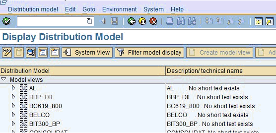
The Display Distribution Model window is displayed in the default Display mode, which shows the current model view entries, as shown in Figure A-43.
Figure A-43 Display Distribution Model Window
Description of "Figure A-43 Display Distribution Model Window"
-
Expand the tree to view the entries for each model view.
To add items, the transaction must be switched into "change mode".
-
Click Distribution model and select Switch processing mode, as shown in Figure A-44.
Figure A-44 Switch Processing Mode Option

Description of "Figure A-44 Switch Processing Mode Option"
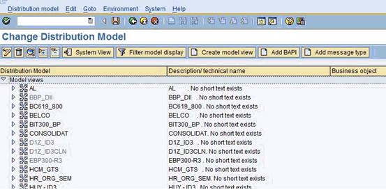
The screen refreshes and the model view window is switched to Change Distribution Model, as shown in Figure A-45.
Figure A-45 Change Distribution Model Window
Description of "Figure A-45 Change Distribution Model Window"
-
From the available menu buttons, select Create Model View.
The Create Model View dialog is displayed, as shown in Figure A-46.
-
Enter a Model View name in the Short text field and a name in the Technical name field, which also serves as a description.
A good convention is to use names starting with the letter Z, since SAP does not overwrite these names in case of system updates. This is only the name of the Model View.
-
Click the green check mark icon to enter the information.
The screen refreshes and returns to the main Change Distribution Model window. The Distribution Model configured is now added to the list, as shown in Figure A-47.
Figure A-47 Change Distribution Model Window

Description of "Figure A-47 Change Distribution Model Window"
The Model View is in temporary transaction storage (and the entry appears in lighter color) until you click the Save icon. If the system connection is lost or times out, then the entry is lost. As a best practice, save your changes after each dialog during the Distribution Model configuration process to avoid losing changes.
-
Place the cursor on the entry previously defined.
The entry is now highlighted, as shown in Figure A-48.
-
In the middle menu bar, click the Add Message Type button.
The Add Message Type dialog is displayed.
-
Enter the ALE Central Instance Sender.
Consult your SAP administrator for this information.
-
Enter the Receiver (for example, ORACLETDS) in the Receiver field.
-
Enter a valid Message Type.
-
Repeat this procedure for each outbound Message Type in this partner scenario, as shown in Figure A-49.
Defining a Partner Profile
Note:
You can skip this section if you are reusing a Partner Profile that has been previously defined.A Partner Profile defines for each logical system, the messages processed, and how the message is processed. This allows for flexible configuration of processing details for partners. Each message type may have only one entry in a Partner Profile. To define a Partner Profile:
-
Run the we20 transaction, as shown in Figure A-50.
The Partner profiles window is displayed, as shown in Figure A-51.
-
Select Partner Type LS and click the white icon on the middle menu bar. You can also select Create from the top menu.
The right side of the screen changes to a blank Partner Profile form, as shown in Figure A-52.
-
Enter the name of the Logical System (for example, ORACLETDS) in the partner number field and click the Save icon.
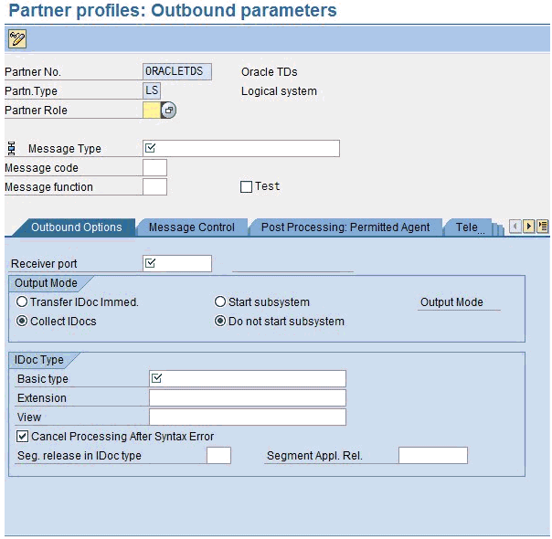
The screen changes with the new profile, as shown in Figure A-53.
Figure A-53 Partner Profiles: Outbound Parameters
Description of "Figure A-53 Partner Profiles: Outbound Parameters"
-
Enter the Message Type in the Message Type field.
-
Enter the Port Number in the Receiver Port field
-
Select the Transfer IDoc immed. button or select Collect IDoc, specify a batch size, and use bd87 to release IDocs for processing.
-
Enter the Basic Type (MATMAS05 for MATMAS, etc.).
-
Click the Save icon.
Testing the SAP R/3 ALE Configuration
In the SAP Server, the BD12 transaction enables the sending of Master Data IDocs to any logical system, for example, to an event adapter.
Testing the SAP R/3 ALE Configuration
To test the SAP R/3 Application Link Embedding (ALE) configuration:
-
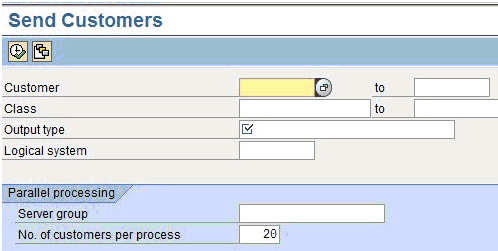
In the Send Customers window, enter the IDoc message type (for example, DEBMAS) in the Output type field, as shown in Figure A-54.
-
In the Logical system field, enter the logical system, for example, ORACLETDS
-
Click Run.
The SAP R/3 event adapter receives the IDoc in XML format. No response is expected from the event adapter.
A confirmation message is displayed, as shown in Figure A-55.
The same number of communication IDocs should also be generated. The IDocs should appear at the adapter server shortly. If no IDocs appear, then check the following:
-
The Collect IDocs option is selected in the Partner Profile (go to bd87 to release).
-
No other server exposing the same Program ID.
-
Before IDocs can be received from SAP, a channel for the Oracle Application Adapter for SAP R/3 must be configured using Application Explorer. In addition, configuration on the SAP application server is also required.
-
Create a RFC Destination (via SM59) or use the same destination defined in the previous section (SAP RFC Outbound Outline).
-
Enter a Destination Name.
-
Enter a Registered Program ID.
-
In the MDMP & Unicode tab, ensure that the Unicode option is selected.
-
Start Oracle BPEL/Mediator.
-
Enter the same Registered Program ID value from step b for the BPEL or Mediator channel.
-
Start the channel.
-
Test the connection using the Test button in SAP.
-
-
Create or use a Logical System as described in "Configuring a Logical System".
-
Define or use a Distribution Model as described in "Configuring a Distribution Model for a Logical System".
-
Create an SAP Transactional RFC Port via transaction WE21.
-
Create an SAP Outbound Partner Profile via transaction WE20.

