|
|
You can use the graphical interface of XQuery Mapper to create data transformations, by mapping elements in source schemas to elements in a target schema. XQuery Mapper generates an XQuery, which is saved as an .xq file.
The procedure to transform data using XQuery Mapper is described in the following sections:
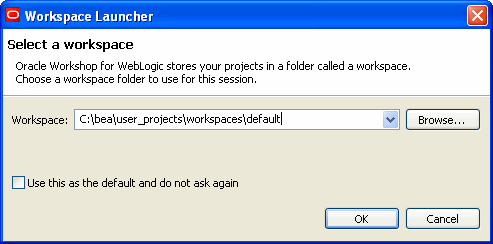
The Workspace Launcher dialog box is displayed.
| Note: | If required, select the Use this as the default and do not ask again check box, and click OK. |
The XQuery transformation perspective launches automatically when you open an XQuery file. If, however, XQuery Mapper is open and no XQuery file is open, you must launch the XQuery transformation perspective manually.
The XQuery Mapper sample project includes sample schema and XML files, which you can use to create XQuery transformations as described in Examples: Data Transformation Using XQuery Mapper.
You can create the sample project by using a wizard from within the XQuery transformation perspective.
To learn more about creating projects and importing the files you need for those projects, see the following topics:
| Note: | You can import project-specific XML schemas, Web Service Definition Language (WSDL) files, and Message Format Language (MFL) files from any location. Before you import the files, it is recommended that you create a folder structure that meets your business needs. For more information, see Importing and Creating Schema Files. |
The New Project wizard is displayed.
Schema files can be created in and imported from any location. The following schema types are supported:
MFL files are created using the Format Builder tool and have the .mfl extension. For more information, see the
Format Builder Online Help.
The Import wizard is displayed.
After the schemas files or MFL files are imported, they are available in the New XQuery Transformation wizard.
The following figure shows how the imported XML schemas are displayed in the New XQuery Transformation wizard.
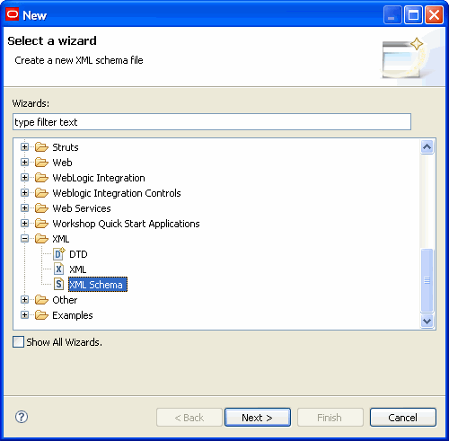
You can create XML schemas by using the XML Schema Editor.
The schema file is created in the specified project. You can now specify the details of the schema and save the file.
For information about using the XML Schema Editor, see Introduction to the XSD Editor at http://www.eclipse.org/webtools/community/tutorials/XMLSchemaEditor/XMLSchemaEditorTutorial.html.
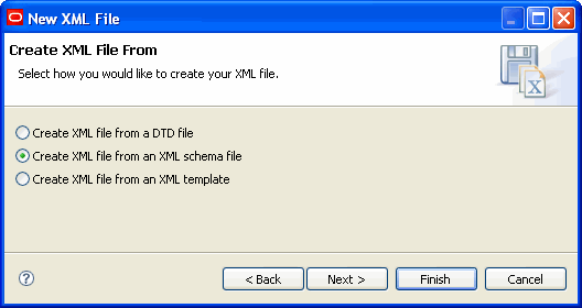
The Create XML File dialog box is displayed.
The XML file is created in the specified folder. You can now specify the details of the file and save it.
For information about using the XML Editor, see Creating XML files Tutorial at http://www.eclipse.org/webtools/community/tutorials/XMLWizards/XMLWizards.html.
The WSDL file is created in the specified project.
For information about using the WSDL Editor, see Introduction to the WSDL Editor at: http://www.eclipse.org/webtools/community/tutorials/WSDLEditor/WSDLEditorTutorial.html.
You can create MFL files by using the Format Builder tool (Start > Programs > Oracle WebLogic Integration > WebLogic Integration 10gR3 > Format Builder).
For more information about the Format Builder tool, see Format Builder Online Help.
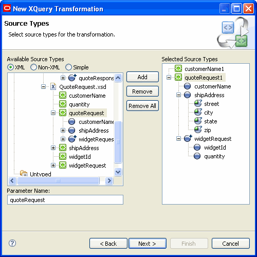
Before you create a data transformation, you must define the source target types and a target data type. The source and target types can be non-XML, XML, and simple data types.
The New XQuery Transformation wizard is displayed.
.xq file.The Source Types dialog box is displayed.
| Note: | For schemas to be displayed in the Available Source Types and Available Target Types pane, the XML and non-XML files that contain these schemas must first be imported into or created in Workshop. |
| Note: | The Available Source Types and Available Target Types panes show only schemas that exist in the schemas folder of the XQuery Transformation project. If you prefer to keep your schemas in any other folder, you must specify the path to that folder in the XMLBeans settings for the project (by choosing Project > Properties, the XMLBeans page, and then the Source Paths tab). |
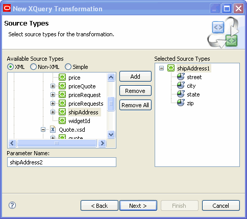
For example, to add input data from schemas/Dates.xsd, select the date element in the schema as the input element and click Add, as shown in the following figure.
The elements and attributes that make up the selected element are displayed in the Selected Source Types pane.
The Target Types dialog box is displayed.
The elements and attributes that make up the selected element are displayed in the Selected Target Type pane.
| Note: | You can specify only one target data type. |
The .xq file is displayed in the Design view. It shows the source and target data types that you selected.
You can perform the following types of data transformations:
Basic element transformation involves mapping a source element to a target element. The source and target elements may have the same name, type, or scope.
The following are some examples of the types of basic element transformation that you can perform:
The XQuery file is created as described in Selecting Source and Target Data Types.
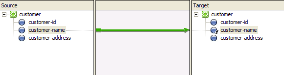
For example, to create a link between the customer-name element in the source schema and the customer-name element in the target schema, drag customer-name from the Source pane to the Target pane. An arrow connects the two elements, as shown in the following figure.
| Note: | While dragging from the Source pane to the Target pane, a dashed line appears temporarily between the two elements. For more information about link patterns, Link Patterns. |
Basic attribute transformation involves mapping a source attribute to a target attribute. The source and target attributes may have the same name, type, or scope.
The following are some examples of basic attribute transformations:
The XQuery file is created as described in Selecting Source and Target Data Types.
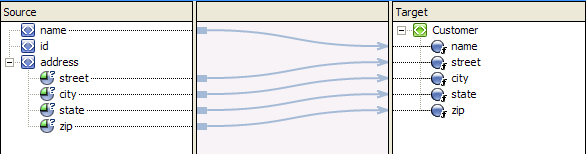
For example, to create a link between the street attribute of the address element in the source schema and the street element of the target schema, drag the street attribute from the Source pane to the Target pane, as shown in the following figure.
Similarly, you can create element-to-attribute and attribute-to-attribute links.
Complex transformations involve mapping a complex source (for example, a repeating element) to a complex target (for example, a nonrepeating element). The following are some examples of complex transformations:
The XQuery file is created as described in Selecting Source and Target Data Types.
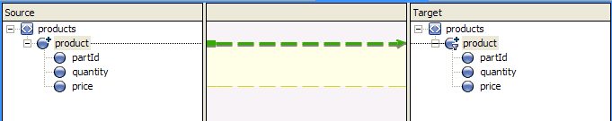
For example, to create a link between product (a repeating group in the source schema) and product (a repeating group in the target schema), drag product from the Source pane to the Target pane, as shown in the following figure.
After creating a data transformation in the Design view, you can add, change, and delete XQuery code either by editing code directly in the Source view or by adding complex expressions in the Design view.
| Note: | For information about the XQuery language, see http://www.w3.org/XML/Query. |
This section contains information about the following topics:
| Note: | If the XQuery file is XQuery 2002-compliant, it opens automatically in the XQuery 2002 Transformation Editor, which has only Source and Test views. For more information, see Support for XQuery 2002 and 2004. |
The XQuery code is displayed. Invalid code is underlined in red.
| Note: | If necessary, you can delete the data transformations in the Source view by deleting all the code within the function except the root element. |
The Constraints view in the XQuery transformation perspective allows you to constrain or manipulate the relationship between source and target repeating elements.
The following Constraint Type options are available in the Constraints view:
When you create transformations between repeating elements, for loops are generated to iterate through the repeating elements. You can limit or constrain the target repeating elements by adding where clauses to the for loops in the Where Clause pane of the Constraints view.
You can create complex conditions (joined by OR or AND operators) for the where clause, as shown in the following code example:
((data($PurchaseOrderDoc/partId) > 200 and data($PurchaseOrderDoc/partId) <= 400))
At run time, the for loop iterates over only those repeating elements that fulfill the complex condition.
For a detailed example on using the Constraints view, see Creating Repeating-Source to Nonrepeating-Target Transformations.
See Creating Unions.
The Target Expression view allows you to create if-then-else expressions.
When a query that contains an if-then-else expression is executed, the conditions that make up the if expression are evaluated. Depending on the result, different values are returned for the target node.
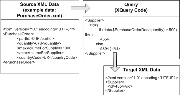
Figure 2-9 shows XQuery code that can be used to implement the following logic:
You can add multiple expressions to the If condition, as shown in the following figure.
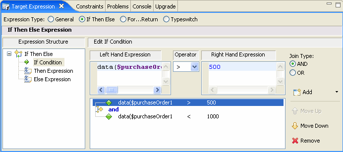
You can change the position of a condition by selecting it and then clicking the Move Up or Move Down button. You can also remove a condition by selecting it and then clicking Remove.
| Note: | In the Edit If Condition pane, even if you remove all the expressions by using the Remove button, the if-then-else expression is not removed entirely in the Source view. The expressions associated with the if condition are removed, but the then and else expressions are retained, as shown in the following listing. |
| Note: | <ns0:partId> |
| Note: | The XQuery always returns the then expression. The else expression is retained in the code so that you can reuse it in the future, if required. |
For more information, see Creating Nested If-Then-Else Expressions.
The Target Expression view allows you to create FLWOR expressions, as shown in the following figure.
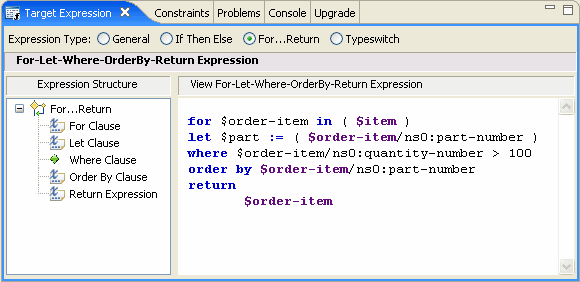
The following table describes the components of FLWOR expressions.
You can insert nested expressions under For, Let, Order By, and Return by right-clicking on them and selecting the required expression from the menu.
| Note: | In the Design view, if you create a link between repeating elements, a For...Return expression (implicit FLWOR expression) is generated automatically in the Source view. You can add Where clauses to this FLWOR expression by using the Constraints view, but you cannot add Let and Order By clauses. Implicit FLWOR expressions are not shown in the Target Expression view. |
For more information, see Creating FLWOR Expressions.
Typeswitch expressions may be required in the following situations:
The Target Expression view lets you create typeswitch expressions, as shown in the following figure.
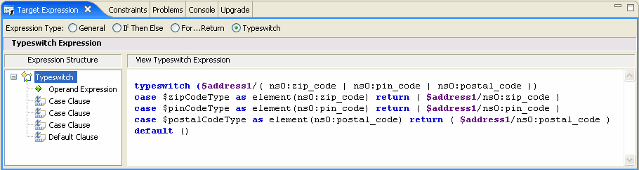
The following table describes the components of typeswitch expressions.
A set of standard W3C XQuery functions and operators is provided in XQuery Mapper. You can add standard XQuery or user-defined functions in XQuery files and data transformation files. For example, you can, use the upper-case XQuery String function to convert the characters in an XML String value to uppercase characters.
| Note: | For more information about XQuery 1.0 and XPath 2.0 functions and operators (W3C Working Draft 23 July 2004), see http://www.w3.org/TR/2004/WD-xpath-functions-20040723/. |
The Expression Functions view is part of the XQuery transformation perspective.
If the Target Expression view is not visible, choose Window > Show View > Target Expression.
In the General Expression pane, the XQuery code linking the selected target and source node is displayed and is selected. Keep this selected for the next step.
For this example, from the String Functions folder, select the upper-case function, which converts all the characters of the source element to upper case.
upper-case function to the General Expression pane.
Leave the parameter of the selected function (the $string-var parameter of the upper-case function in this example) in the General Expression pane selected.
| Note: | XQuery functions that are defined by Oracle (example: trim-left) are prefixed with fn-bea:. |
| Note: | XQuery functions that are not listed in the Expression Functions view but defined in the XQuery specification, can be used with the fn: prefix. |
The variables (and their subelements) that you can use in an XQuery are displayed in the Expression Variables view.
| Note: | If the Expression Variables view is not displayed, choose Window > Show View > Expression Variables. |
The following types of variables are displayed in the Expression Variables view:
for loops generated by structural links.These variables are in scope for all the subelements of the node that has the structural link.
You can insert expression variables in the following ways:
Drag the variables or their subelements from the Expression Variables view, and drop them in the Constraints or Target Expression view.
$ and choose a variable from the pop-up menu$) in the required text field. For example, enter $ in the General Expression pane of the Target Expression view.A pop-up menu containing a list of the available variables is displayed.
/).If subelements exist, a pop-menu containing a list of the available subelements is displayed.
/).If further subelements exist, a pop-menu containing a list of the available subelements is displayed.
While editing an XQuery file in the Design view, you can view the schema properties of nodes in the current transformation in the Properties view, without opening the source and target XSD or MFL files.
To display the Properties view, choose Window > Show View > Properties.
| Note: | To change the schema properties of an element or attribute, edit the corresponding schema file (XSD for XML schema and MFL for non-XML schema). |
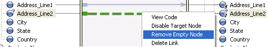
If the target schema in a data transformation contains an optional element (minOccurs=“0”), you can design the link to the element such that the element is included in the output XML file only if it contains a value (that is, the element is not empty in the source XML file).
Consider the source XML data in the following listing.
<address>
<Address_Line_1>1 Elm Street</Address_Line_1>
<Address_Line_2/>
<City>San Jose</city>
<State>California</State>
<Country>US</Country>
</address>
The Address_Line_2 element is optional and empty. If Address_Line_2 is mapped to a corresponding element in the target schema, then, by default, the output XML file contains an empty Address_Line_2 element.
You can restrict output of such optional elements by right-clicking on the link and selecting Remove Empty Node, as shown in the following figure.
The XQuery code underlying the link is enclosed in an if-then-else expression that causes the target element to be produced only if the transformation results in a nonempty value.
You can remove the if-then-else expression by right-clicking on the link and selecting Retain Empty Node, as shown in the following figure.
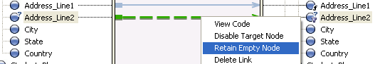
| Note: | The Remove Empty Node (or Retain Empty Node) option is displayed only when you right-click on a link to an optional target element. |
After creating an XQuery transformation in the Design view, you can test whether the expected XML or non-XML output is generated properly in the Test view.
You can use the autogenerated XML files or your own custom XML and non-XML files for testing the transformations.
The following figure shows the features of the Test view.
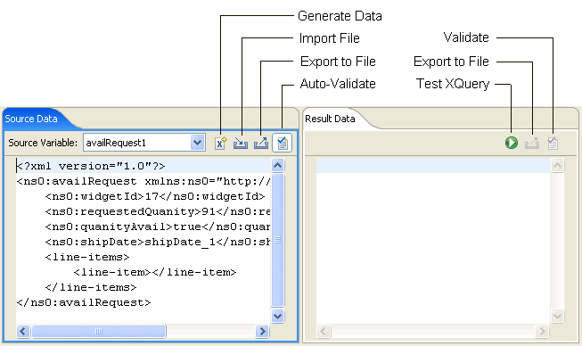
The values available in the Source Variables drop-down list are based on the source XML schemas of the transformation that you are testing. When you select one of these schemas, an XML file is generated automatically and displayed.
| Note: | These XML files are not saved automatically; you can save them by clicking the Export icon. |
| Note: | To use a custom XML file (instead of the autogenerated XML files) or a non-XML file (such as MFL) for testing the transformation, you can import the file by clicking the Import icon. |
When you select the Test view, XQuery Mapper generates an initial set of sample data and displays it in the Source Data pane.
If you want to regenerate the sample data, click Generate Data. You might, for example, want to start testing afresh with new sample data if edits have resulted in XML data that is no longer valid for the input schema.
If the XQuery that you want to test has multiple source types, you can generate sample data for each source type by selecting the required source type in the Source Variable drop-down list and then clicking the Generate Data icon.
You can also manually edit the generated XML data.
| Note: | For complex input schemas, the generated XML data may not comply with the schema. Validation errors are underlined in yellow in the Source Data tab. When you place the mouse pointer over an error, details of the error are displayed. You can correct the generated XML data to make it comply with the input schema. |
You can import data from an XML (or non-XML) file and test the transformation using that data.
In addition, if the XQuery that you want to test has multiple source types, you can import sample data for each source type by selecting the required source type in the Source Variable drop-down list and then clicking the Import File icon.
If the Auto Validate option is selected, then, when you import data, the data is validated against the associated schema. Errors are underlined in yellow. When you place the mouse pointer over an error, details of the error are displayed.
| Note: | You can import XML data for global types and local elements, but global types and local elements are not validated and no errors or warnings are reported for invalid data. For more information, see XML Global Elements, Global Types, Local Elements, and Attributes. |
The Auto Validate option in the Source Data pane and the Validate option in the Result Data pane are enabled only if the source parameter or result data is an XML global element.
The validation options are not available for the following data types:
| Note: | In any case, untyped non-XML (raw) data cannot be used in data transformations. |
For more information, see XML Global Elements, Global Types, Local Elements, and Attributes.
Selecting the Auto Validate option causes the source data to be validated automatically against the source schema every time the data is changed.
You can use the Validate option to validate the result of the transformation against the target schema.
| Note: | The validation at design time in the Test view is not the same as the schema validation that occurs at run time. Validation at design time does not modify the resulting XML document, but it does check for existence of elements and attributes that are defined as required in the schema. |
Restrictions Applicable to the XQuery Test View
This section provides information to help you use the graphical features of XQuery Mapper and interpret the graphical representations in the Design view of XQuery Mapper.
The following table lists the options available in the Design view of XQuery Mapper when you right-click on a link or element.
Links in XQuery Mapper are shown in different colors and patterns to help you distinguish easily between different link types. The following table describes the graphical representation of the links that you create in XQuery Mapper.

|
|||

|
|||
|

|
||
|
|
|||

|
|||

|
|||

|
|||

|
|||

|
|||

|
|||

|
|||
|
When you drag a node from the Source pane to the Target pane, a temporary link (dashed line) appears between the two nodes. The color of the line changes depending on the compatibility between the source and target nodes.
When you finish creating the link, a dotted or dashed line (depending on the source and target nodes) is displayed.
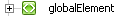
An XML schema type or element is considered global if it is a direct child of the schema element and local if it is not a direct child of the schema element (that is, the element is nested within another element).
The following example XML schema illustrates this difference.
<?xml version="1.0"?>
<xs:schema xmlns:xs="http://www.w3.org/2001/XMLSchema"
targetNamespace="http://www.acme.org/globalExample"
xmlns="http://www.acme.org/globalExample"
elementFormDefault="qualified"
attributeFormDefault="unqualified">
	<xs:element name="globalElement">
		<xs:complexType>
			<xs:sequence>
				<xs:element name="localElement"
					minOccurs="1" maxOccurs="1"
					type="xs:string" />
			</xs:sequence>
			<xs:attribute name="attribute"
				type="xs:string" use="required"/>
		</xs:complexType>
	</xs:element>
	<xs:complexType name="globalType">
		<xs:sequence>
			<xs:element name="anotherLocalElement"
			minOccurs="0" maxOccurs="unbounded"
			type="xs:string" />
		</xs:sequence>
	</xs:complexType>
</xs:schema>
In the preceding XML schema, globalElement is global because it is a direct child of the schema element, whereas localElement is local because it is a child of globalElement.
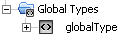
You can also define a global type, as shown by the globalType element toward the end of the preceding XML schema. While you can have only one global element in an XML schema, you can declare many elements (with different names) of the same global type in a single XML schema.
The following table shows the graphical representations of the different XML components in XQuery Mapper.


|