6 Creating the Project in JDeveloper Examples
This chapter contains the following topics:
Getting Started
This topic describes the components necessary to work with the samples and how to prepare your system.
The following are installation and configuration requirements for using the examples.
-
Personal computer running Microsoft Windows XP, Windows Vista, Windows Server 2003, or Windows Server 2008 with one GB of RAM.
-
The Tuxedo adapter that you are using (Tuxedo orTuxedo Queue) must be deployed to the Oracle Application Server.
-
OracleAS Tuxedo Adapter must be configured for outbound or inbound processing. See fix link.
-
Oracle JDeveloper must be installed.
-
Legacy adapter must be deployed.
-
Oracle Studio with the necessary machines loaded. See Configuring OracleAS Adapters for Tuxedo in Oracle Studio.
This chapter provides examples of the configuration steps that are used when using BPEL to work with the Oracle Tuxedo adapters. You should be familiar with the following before working with these examples:
-
How to create J2CA connections. See Integrating OracleAS Adapters for Tuxedo with WebLogic for more information.
-
How to configure the OracleAS adapters for Tuxedo using Oracle Studio. See Configuring OracleAS Adapters for Tuxedo in Oracle Studio for more information.
Integration between the OracleAS adapters for Tuxedo and BPEL has the following processes:
-
Design Time: The OracleAS adapters for Tuxedo are configured with Oracle Studio as described in Configuring OracleAS Adapters for Tuxedo in Oracle Studio.
-
Run time: After you deploy the BPEL process with JDeveloper, you can test your configurations. See
Deploy a BPEL Inbound Process
This section describes how to create a BPEL inbound process that connects to a Tuxedo adapter. For information on how to configure a Tuxedo adapter for inbound, see fix link.
To configure a process with the BPEL process manager, you use JDeveloper. This section describes how to create a BPEL inbound process for Tuxedo adapters using JDeveloper. There are two configuration types necessary to perform this inbound sample.
Before you design the inbound process, you integrate and connect your OracleAS adapter for Tuxedo with the BPEL process manager. See Integrating OracleAS Adapters for Tuxedo for more information.
Beginning Tasks
Before you design the inbound process, you must perform the following:
-
Integrate the OracleAS Adapter for VSAM. See Integrating OracleAS Adapters for Tuxedo with WebLogic for more information.
-
Configure the connection for the J2CA VSAM resource adapter. You do this by creating a connection factory. See Configuring the Tuxedo Queue Inbound Adapter for information on how to do this.
-
Write a schema file. First, create an interaction called
findDoctorusing Oracle Studio. See Configuring the Tuxedo Queue Inbound Adapter for more information. -
Create a BPEL PM Server Connection in JDeveloper.
-
Create the WSDL and binding file for the interaction. You do this in Oracle Studio before you begin to build your endpoint in JDeveloper. Oracle Studio creates the WSDL and binding (jca) files automatically based on the interaction you create. See fix link for information on creating these files.
Design-Time Configuration
This section describes the design-time steps necessary to deploy a BPEL inbound process:
Create a BPEL Inbound Process
Perform the following to create a BPEL project for inbound.
-
In JDeveloper, create a new SOA project
-
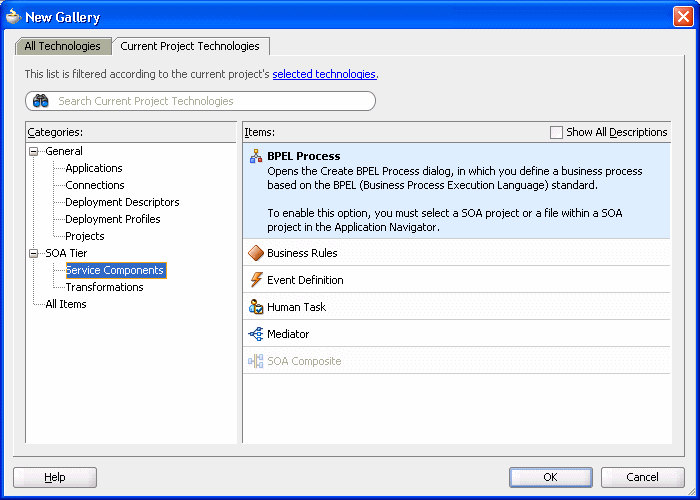
Right-click the SOA project and select New. The New Gallery is displayed as shown in Figure 6-1.
-
In the Categories list, expand SOA Tier and select Service Components.
-
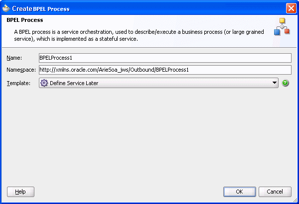
From the Items list, select BPEL Process then click OK. The Create BPEL Process screen is displayed as shown in Figure 6-2.
-
Enter the following in the BPEL Process screen:
-
Enter a name for the BPEL process, for example BPELInbound1.
-
From the Template list, select Define Service Later.
-
-
Click OK. The BPEL process is displayed in the visual editor.
Continue with Use a Third-Party Adapter for the Inbound Process.
Use a Third-Party Adapter for the Inbound Process
You use a third-pary adapter as a partner link to create the inbound process. SOA executes the SQL statement defined in the interaction and passes it to a resource adapter. Perform the following to create the third-party adapter.
-
From the Projects area, on the left side, double-click the
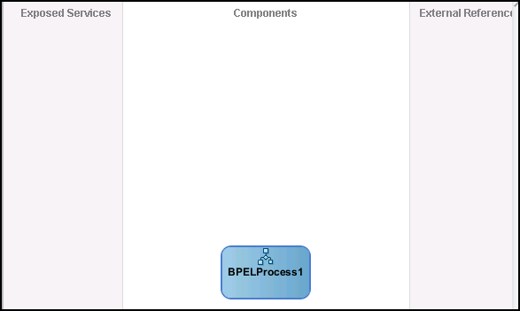
composite.xml. At the bottom of the visual editor, click the Design tab, if necessary. Figure 6-3 shows the Composite view in the visual editor. -
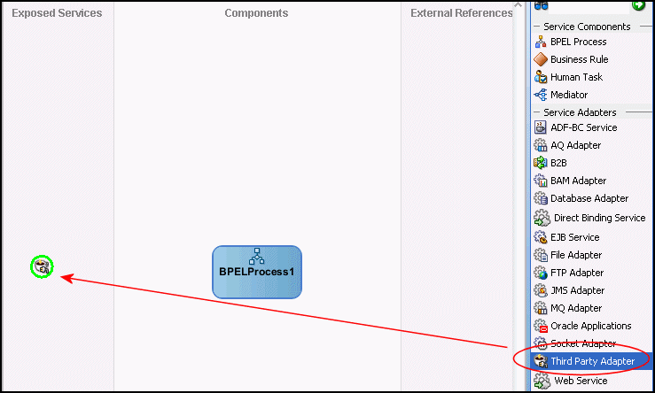
Drag a third-pary adapter into the Exposed Services lane of the visual editor, as shown in Figure 6-4.
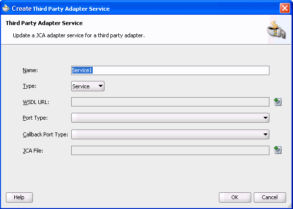
When you drag the third-party adapter into JDeveloper, the Create Third Party Adapter Service screen is displayed as shown in Figure 6-5.
Figure 6-5 Create Third-Party Adapter Service
Description of "Figure 6-5 Create Third-Party Adapter Service"
-
Click the button next to the WSDL URL field and browse to the WSDL file you are using.
-
In the Type list, select Service.
-
Click the button next to the JCA File field and browse to the binding file you are using.
-
Click OK to close. You should now have a composite design as shown in Figure 6-6.
Figure 6-6 Ready to Create BPEL Process (Composite View)
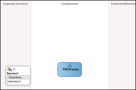
Description of "Figure 6-6 Ready to Create BPEL Process (Composite View)"
Continue with Design the BPEL Inbound Process.
Design the BPEL Inbound Process
Before you begin to design the inbound process procedure,you may need to configure some activation spec properties in the binding (jca) file. For more information on working with the inbound binding file, see Configuring the Binding for Tuxedo Queue Inbound Interactions.
Do the following to define the BPEL inbound process.
-
In the Composite, connect the BPEL process to the third-pary adapter as shown in Figure 6-7.
Figure 6-7 Connect to Third-Party Adapter
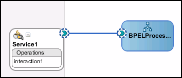
Description of "Figure 6-7 Connect to Third-Party Adapter"
-
Double-click the BPEL Process.
-
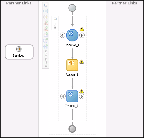
From the Component Palette, BPEL Process Activities section, drag a Receive, Assign, and Invoke process into the editor as shown in Figure 6-8.
-
In the Visual Editor, connect the Receive activity to the third-party adapter service (
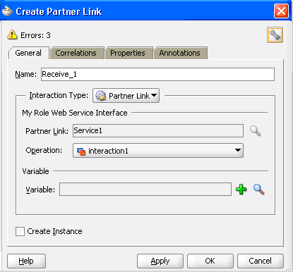
Service1). The Edit Receive dialog box is displayed as shown in Figure 6-9. -
Do the following in the Edit Receive dialog box:
-
Enter a name for the Receive activity.
-
Create the variable. Click the plus sign to the right of the Variable field, then click OK in the Create Variable dialog box that is displayed.
-
Ensure that the Create Instance check box is selected.
-
-
Click OK to close the dialog box and accept the information then Deploy the Project.
Deploy the Project
Perform the following to deploy the project to the Oracle Application Server:
-
From the Application Navigator, right-click the project and find Deploy and then select the project you are deploying.
-
From the Deploy wizard, select Deploy to Application Server.
-
Continue to click Next till the end of the wizard and then click Finish to deploy.
Create the Connection
This section describes how to create a connection to the adapter files you are using. Do the following to create the connection.
-
Create a file adapter and give it a name, for example
WriteRes. -
Click Next and select Write File. Give the file a name, for example
Write Message. -
Click Next and enter the path to the message file you want to write to.
-
In the Message Schema chooser, browse to the file
message.xsd. You should have made sure that this file was created before you started this process. See the beginning of the section, Design the BPEL Inbound Process for more information. -
Select the Message type,
bigOrderEventand then click OK. -
Create an Input Variable with the default name for the Invoke activity.
-
Create a Copy Operation for the Assigned activity.
Run-time Configuration
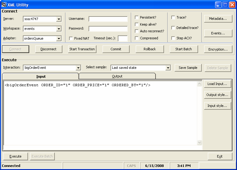
This section describes how to test the project and run it to see that the inbound process is executed successfully. By using the XML utility, you call an event in Oracle Connect that is defined in the file adapter you created. See Create the Connection. Because this event is called from Oracle Connect it is an inbound event. Events that originate with SOA services in the OracleAS, it is an outbound event. For more information, see Deploy a BPEL Outbound Process. The Runtime configuration for inbound has one step called Triggering the Event using the XML Utility.
Triggering the Event using the XML Utility
Use the XML utility to create an SQL statement to trigger the event you are requesting. Do the following to trigger the event.
-
From the Start menu, select All Programs, then Oracle, then Server Utilities, and then XML Utility. The XML Utility is displayed.
-
Enter the following information in the Connect section of the XML utility:
-
Server: The name of the machine where the OracleAS adapter for Tuxedo is located.
-
Workspace: The name of the workspace where the OracleAS adapter for Tuxedo is located. A list of available workspaces is shown in the list for this field. The workspaces are defined in Oracle Studio.
-
Adapter: The name of the OracleAS adapter for Tuxedo. A list of available adapters is shown in the list for this field. The adapters are defined in Oracle Studio.
-
-
Click Connect to connect to the selected machine.
-
In the Interaction field, enter the name of the interaction to call. This is defined in Oracle Studio.
-
In the Input window, enter a statement to call the interaction. You can see an example in the above figure.
-
Click Execute. If successful, you get a return similar to the following example:
<?xml version="1.0"?>
<bigOrderEvent ORDER_ID="1"ORDERED_BY="1" xmlns+"noNamespace://ordersQueue"/>
Mediator Inbound Process
This section describes how to create a Mediator inbound process that connects to a OracleAS adapter for Tuxedo.
You use JDeveloper to configure a process with Mediator. This sectino describes how to create a Mediator outbound process for Tuxedo resource adapters using JDeveloper. The following topics describe thow to deploy a BPEL outbound process.
Beginning Tasks
Before you design the inbound process, you must perform the following:
-
Integrate the OracleAS Adapter for VSAM. See Integrating OracleAS Adapters for Tuxedo with WebLogic for more information.
-
Configure the connection for the J2CA VSAM resource adapter. You do this by creating a connection factory. See Configuring the Tuxedo Queue Inbound Adapter for information on how to do this.
-
Create the WSDL and binding file for the interaction. You do this in Oracle Studio before you begin to build your endpoint in JDeveloper. Oracle Studio creates the WSDL and binding (jca) files automatically based on the interaction you create. See fix link for information on creating these files.
Create a Mediator Inbound Process
Perform the following to create an inbound Mediator project.
-
In JDeveloper, create a new SOA project
-
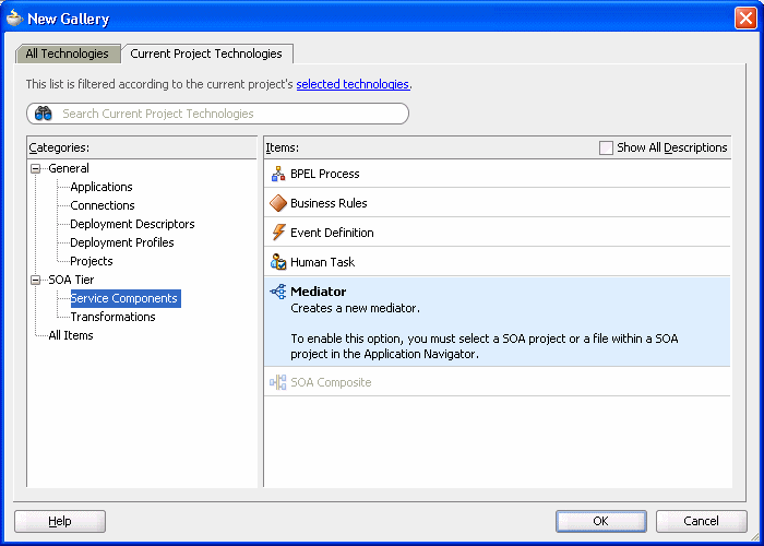
Right-click the SOA project and select New. The New Gallery is displayed as shown in Figure 6-11.
-
In the Categories list, expand SOA Tier and select Service Components.
-
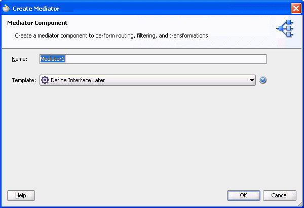
From the Items list, select Mediator then click OK. The Create Mediator screen is displayed as shown in Figure 6-12.
-
Enter the following in the BPEL Process screen:
-
Enter a name for the Mediator process, for example MedInbound1.
-
From the Template list, select Define Service Later.
-
-
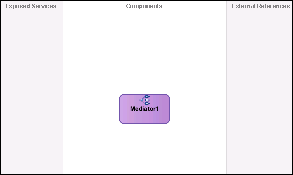
Click OK. The Mediator process is displayed in the visual editor.
Continue with Use a Third-Party Adapter for the Inbound Process.
Use a Third-Party Adapter for the Inbound Process
You use a third-pary adapter as a partner link to create the inbound Mediator. SOA executes the SQL statement defined in the interaction and passes it to a resource adapter. Perform the following to create the third-party adapter.
-
From the Projects area, on the left side, double-click the
composite.xml. At the bottom of the visual editor, click the Design tab, if necessary. Figure 6-13 shows the Composite view in the visual editor. -
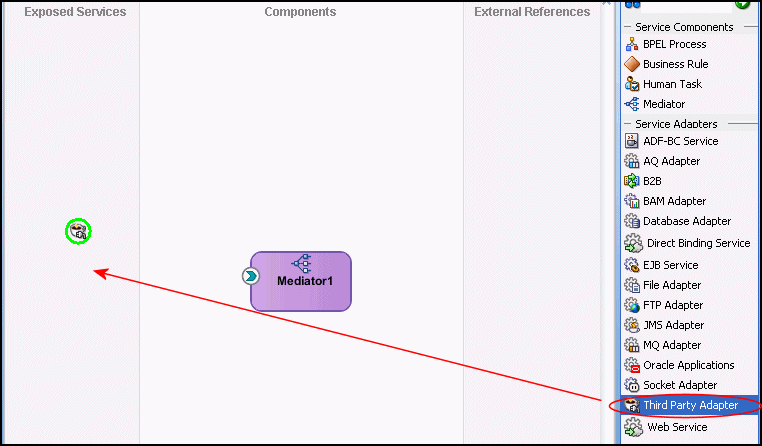
Drag a third-pary adapter into the Exposed Services lane of the visual editor, as shown in Figure 6-14.
When you drag the third-party adapter into JDeveloper, the Create Third Party Adapter Service screen is displayed as shown in Figure 6-15.
Figure 6-15 Create Third-Party Adapter Service

Description of "Figure 6-15 Create Third-Party Adapter Service"
-
Click the button next to the WSDL URL field and browse to the WSDL file you are using.
-
In the Type list, select Service.
-
Click the button next to the JCA File field and browse to the binding file you are using.
-
Click OK to close. You should now have a composite design as shown in Figure 6-16.
Figure 6-16 Ready to Create Mediator (Composite View)
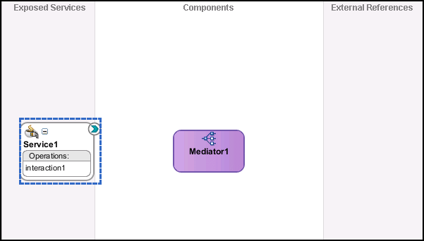
Description of "Figure 6-16 Ready to Create Mediator (Composite View)"
Continue with Create a File Adapter.
Create a File Adapter
Perform the following to create a file adapter.
-
In the Composite, connect the Mediator to the third-party adapter.
-
From the component pallet, SOA section, on the right, drag a file adapter into the External References lane of the visual editor. The Adapter Configuration wizard is displayed.
-
In the first screen of the Adapter Configuration wizard, enter a name for the adapter service, and click next.
-
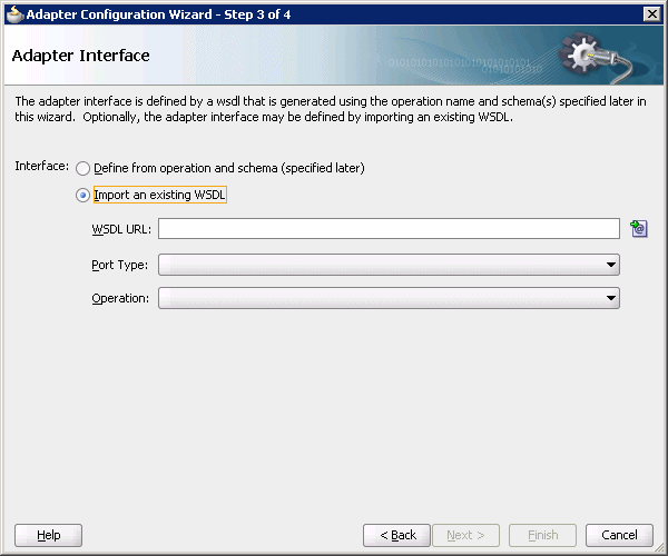
In the Adapter Interface screen, select the same WSDL file as you selected in Use a Third-Party Adapter for the Inbound Process. Figure 6-17 shows the Adapter Interface screen.
-
Click Next to use the default settings for each of the remaining screens in the wizard. When you get to the end click Finish.
-
Connect Mediator to the file adapter and select the operations.
Continue with Design an Inbound Mediator.
Design an Inbound Mediator
In this step, you design the BPEL process. Perform the following ot design the inbound Mediator.
-
In the Composite, double-click the Mediator.
-
Create a static routing rule.
-
Expand the Filter Expression as shown in Figure 6-18.
-
Continue with Create Mapping Rules and Map the Files.
Create Mapping Rules and Map the Files
You must perform the following steps to create mapping files and map the files.
-
In the Filter Expression screen, click the icon next to the Transform using field as shown in Figure 6-18. The Request Transformation Map screen is displayed as shown in Figure 6-19.
-
In the Request Transformation Map, select Create New Mapper file. Use the default value.
-
Click OK.
-
In the visual editor, click to return to the mediator.mplan tab.
-
Click the tab for the Mapper File that you created. Connect the elements.
-
Save and then Deploy the Project.
Deploy the Project
Perform the following to deploy the project to the Oracle Application Server:
-
From the Application Navigator, right-click the project and find Deploy and then select the project you are deploying.
-
From the Deploy wizard, select Deploy to Application Server.
-
Continue to click Next till the end of the wizard and then click Finish to deploy.
Deploy a BPEL Outbound Process
This section describes how to create an BPEL inbound process that connects to a Tuxedo adapter. For information on how to configure a Tuxedo adapter for outbound, see fix link.
To configure a process the BPEL Process Manager, you use JDeveloper. This section describes how to create a BPEL outbound process for Tuxedo adapters using JDeveloper. This section contains the following topics.
Before you design the outbound process, you integrate and connect your OracleAS adapter for Tuxedo with the BPEL process manager. See Chapter 4, "Integrating OracleAS Adapters for Tuxedo" for more information.
Beginning Tasks
Before you design the outbound process, you must perform the following:
-
Integrate the OracleAS Adapter for VSAM. See Integrating OracleAS Adapters for Tuxedo with WebLogic for more information.
-
Configure the connection for the J2CA VSAM resource adapter. You do this by creating a connection factory. See Configuring the Tuxedo Gateway Synchronous Inbound Adapter for information on how to do this.
-
Create a BPEL PM Server Connection in JDeveloper.
-
Create the WSDL for the interaction. You do this in JDeveloper Connections explorer before you begin to build your endpoint in JDeveloper. JDeveloper creates the WSDL automatically based on the interaction you create. In the Connections explorer, browse for the Oracle Connect server you configured in Oracle Studio (see Oracle Application Server Legacy Adapters Installation Guide), then double-click the findDoctor interaction to view and create the WSDL.
Design-Time Configuration
This section describes the design-time steps necessary to deploy two BPEL outbound processes. The processes use the Web service called TOUPPER. This service reads a string of lower-case letters and writes them in upper-case letters. The following are the steps required to create the outbound process.
Before You Begin
Before you design the outbound process, you define the Toupper interaction using Oracle Studio as described in Creating Outbound Interactions with the OracleAS Adapter for Tuxedo.
Create a BPEL Project for a BPEL Outbound Process
Perform the following tasks to create a BPEL project for outbound.
-
In JDeveloper, from the View menu, select Application Navigator.
-
In the Application Navigator, right-click the application you are working with and select New Project. The New Gallery dialog box is displayed.
-
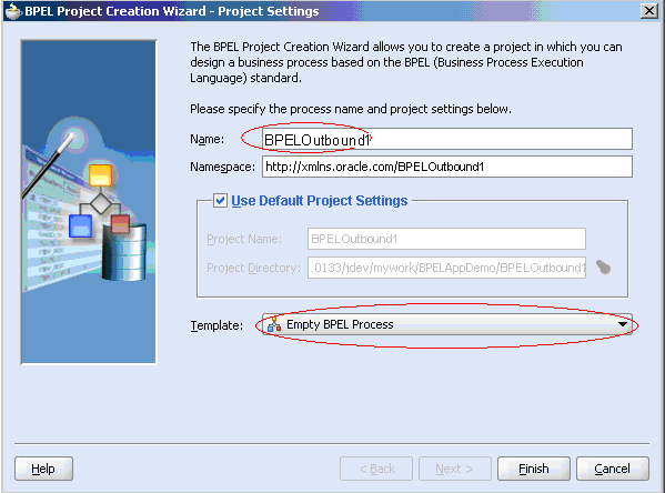
From the Items list, select BPEL Process Project then click OK. The BPEL Project Creation Wizard-Project Settings dialog box is displayed.
-
Do the following in BPEL Project Creation Wizard-Project Settings dialog box:
-
Enter a name for the BPEL process, for example BPELOutbound1.
-
From the Template list, select Empty BPEL Process.
-
-
Click Next to review the input/output schema elements or click Finish.
Create a File Adapter to Read the String
You create a file adapter to read a file as string input. SOA reads this string and passes it to a resource adapter. The resource adapter then processes the information in this string and returns it in Upper case. Do the following to create the file adapter.
-
Drag a PartnerLink into a service lane of the visual editor. The Create Partner Link dialog box is displayed.
Figure 6-21 Partner Link for File Adapter
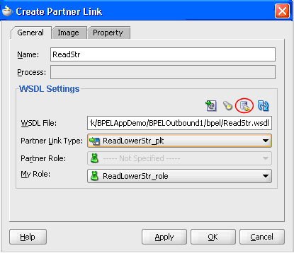
Description of "Figure 6-21 Partner Link for File Adapter"
-
Click the Adapter Wizard button. This is the third button in the WDSL Settings section of the Create Partner Link dialog box, as shown in the figure above.
-
Enter the following information in the Adapter Configuration wizard:
-
Step 1, Adapter Type: Select File Adapter.
-
Step 2, Service Name: type
ReadStr -
Step 3, Operation:
Operation Type: select Read File
Operation Name: Type
ReadLowerStr -
Step 4, File Directories
Directory Names are Specified as: Select Physical Path
Directory for Incoming Files (physical path): Enter the full path to the folder where you want the incoming files, for example
C:\temp. -
Step 5, File Filtering:
Includes Files with Name Pattern: Enter
*xml -
Step 6, File Polling:
Polling Frequency: enter
1then select seconds from the list. -
Step 7, Messages:
Schema File URL: Enter
TOUPPERSchema.xsdSchema Element: Enter
ToUpperData
-
-
Click Finish.
Design a BPEL Outbound Process to Read the String
In this step, you design the BPEL process. Do the following to design the BPEL outbound process:
-
From the Component Palette-Process Activities pane, drag a Receive, Assign, and Invoke activity into the editor for the process you created in the Create a BPEL Project for a BPEL Outbound Process step.
-
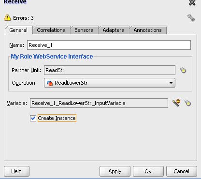
In the Visual Editor, connect the Recieve_1 activity to the ReadStr file adapter. The Edit Receive dialog box is displayed.
-
Do the following in the Edit Receive dialog box:
-
Enter a name for the Receive activity, in this example it is
Receive_1. -
Create the variable. Click the first button to the right of the Variable field, then click OK in the Create Variable dialog box that is displayed.
-
Ensure that the Create Instance check box is selected.
-
Click OK to close the dialog box and accept the information.
-
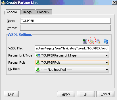
Create a Partner Link to the Tuxedo Adapter
In this step, create a partner link to the Tuxedo adapter you are working with. Do the following to create a partner link.
-
Drag a PartnerLink into a service lane of the visual editor. The Create Partner Link dialog box is displayed.
Figure 6-24 Partner Link to Tuxedo Outbound
Description of "Figure 6-24 Partner Link to Tuxedo Outbound"
-
From the Create Partner Link dialog box, click the Service Explorer button. This button is the second form the left and is shown in the figure in the previous step. The Service Explorer dialog box is displayed.
-
In the Service Explorer, expand the connection you are using, then expand adapters and then applications, and continue to browse until you find the WDSL file you are using. Select the file and click OK.
The WSDL File field in the Create Partner Link dialog box displays the path to the WSDL file you selected. The Partner Link Type field displays the Partner Link defined in the WSDL file.
-
Enter the following information in the Create Partner Link dialog box:
-
In the Partner Role list, select TOUPPERRole.
-
In the My Role list, select Not Specified.
-
Edit the Invoke_1 Activity
Edit the Invoke_1 activity that you added to the Visual Editor so that it invokes the TOUPPER service. Do the following to edit the Invoke_1 activity.
-
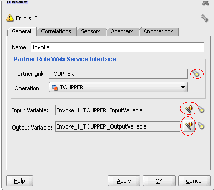
Double-click the
Invoke_1activity to edit it. The Invoke dialog box is displayed. -
In the Invoke dialog box, ensure that the Partner Role Web Service Interface section has the following values:
-
Partner Link:
TOUPPER -
Operation:
TOUPPER
-
-
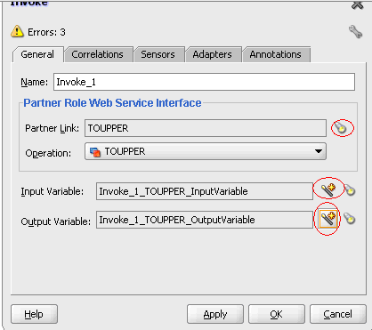
Click the Automatically Create Input Variable button. It is the first icon to the right of the Input Variable field as shown in the figure in the previous step. The Create Variable dialog appears with the input variable.
-
The Input Variable should be
Invoke_1_TOUPPER_InputVariable. Click OK. -
Click the Automatically Create Input Variable button for the Output Variable field.
-
The Output Variable should be
Invoke_1_TOUPPER_OutputVariable. Click OK.
Edit the Assign_1 Activity
You use the assign activity to assign a value to the resource adapter. Do the following to edit the Assign_1 activity.
-
Double-click the
Assign_1activity to edit it. The Assign dialog box is displayed. -
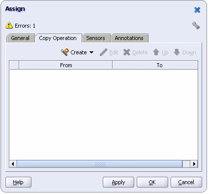
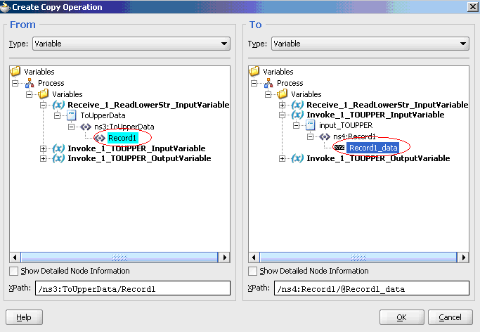
Click the Create list and select Copy Operation. The Create Copy Operation dialog box is displayed.
-
On the From side, expand Variables then expand Read_1_ReadLowerStr_InputVariable, then expand nsx:ToUpperData and select Record1.
-
On the To side, expand Variables then expand Read_1_ReadLowerStr_InputVariable, then expand input:ToUPPER, then expand nsx:Record1 and select Record1_data.
-
Click OK. The Copy Operation tab in the Assign window updates to show the rule.
Create a Process to Write the Upper-Case Letter String
After you create a process that reads a string of lower-case letters, create another process that writes the string in upper case letters. Do the following to create a process that writes the string in upper-case letters.
-
Create a file adapter as described in Create a File Adapter to Read the String. To write the string, use the following values:
-
Service Name: WriteStr
-
Operation Type: Write File
-
Operation Name: WriteUpperStr
-
Directory for Incoming Files: C:\tempOut
-
File Naming Pattern: *.xml
-
-
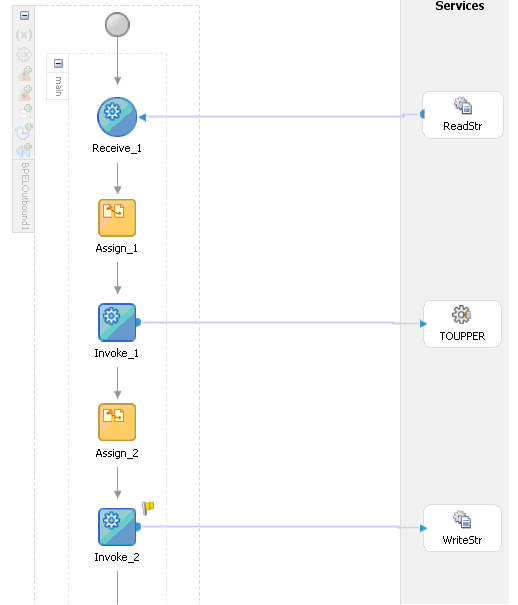
Add an Assign activity and an Invoke activity to the visual editor.
-
Double-click the Invoke_2 activity to edit it. See Edit the Invoke_1 Activity for an explanation on how to edit an invoke activity. Use the following values for the Invoke_2 activity:
-
Partner Link: WriteStr
-
Operation: WriteStr
-
Input Variable: Invoke_2_WriteStr_InputVariable
-
Output Variable: Invoke_1_TOUPPER_OutputVariable
-
-
Double-click the Assign_2 activity to edit it. See Edit the Assign_1 Activity for an explanation on how to edit an Assign activity. Use the following values for the Assign_2 activity:
-
From: Expand Variables then expand Invoke_1_TOUPPER_InputVariable, then expand output:ToUPPER, then expand nsx:TOUPPER_Response and select Record1_data.
-
To: Expand Variables then expand Invoke_2_1_WriteStr_InputVariable, then expand ToUpperData, then expand nsx:ToUpperData and select Record1.
-
The following figure shows how the final process looks:
Runtime Configuration
This section describes how to test the project and run it to see that the outbound process is executed successfully. Do the following to test the outbound process.
-
Create a file and call it
ToUpperIn.xmlas shown in the following example:<?xml version="1.0" encoding="UTF-8"?><CU:ToUpperData xmlns:CU="http://xmlns.oracle.com/Esb/ToUpperData" xmlns:xsi="http://www.w3.org/2001/XMLSchema-instance"> <Record1>tuxedo</Record1></CU:ToUpperData>
-
Save the file to the
C:/tempfolder that was defined for the first file adapter. The file is deleted after the SOA server reads the file and complete the process. -
Open the
C:\tempOutfolder that was defined in the second file adapter. A file with the following contents is copied to this folder.<?xml version="1.0"?> <ToUpperData xmlns="http://xmlns.oracle.com/Esb/ToUpperData"> <Record1 xmlns>="">TUXEDO</Record1>
