| Oracle® Real User Experience Insight User's Guide Release 6.5.1 for Linux x86-64 Part Number E18053-01 |
|
|
View PDF |
| Oracle® Real User Experience Insight User's Guide Release 6.5.1 for Linux x86-64 Part Number E18053-01 |
|
|
View PDF |
This chapter describes how to identify the Web pages to be monitored. In particular, how to define the Web pages for which you want additional information to be available, the logical sequence of pages in user flows to be monitored, and those pages that should be monitored for the occurrence of specific text strings. In addition, the definition of Single Sign On (SSO) profiles and suites are also described. This can only be performed by users with Analytical level access.
Note that URL arguments configured for applications, suites, and services, as well as for user and client ID identification, must be specified without encoding (except for %, &, and = characters).
Page identification within RUEI is based on applications. Essentially, an application is a collection of Web pages. This is because pages on a Web site are typically bound to a particular application. Each page within an application has an assigned name, and belongs to a group. For example, MyShop » Contact » About us refers to the About us page in the Contact group, within the MyShop application.
Each application has a page-naming scheme associated with it, which defines its scope. This can be specified in terms of a partial domain name, URL structure, or a combination of both of these. A page-naming scheme (such as page tagging or the title part of the HTML page) can also be specified to refine the application definition.
For each page that RUEI detects, it uses the available application definitions to assign a name to it. Note that information about any pages that could not be identified using these definitions is discarded and, therefore, not available through reports and the Data Browser.
In addition to automatic detection, application pages can also be defined manually. This is particularly useful in the case of an inconsistent URL structure, or where identified pages contain sub pages, or when you want to assign a different name to the one assigned automatically to it by the application. Note that these manually defined pages take precedence over pages identified automatically through application definitions.
The structure of the currently defined applications, their groups and pages, are visible by selecting Configuration, then Applications, and then Applications. An example is shown in Figure 6-1.
To define applications, do the following:
Select Configuration, then Applications, then Applications, and click New application. The dialog shown in Figure 6-2 appears.
Specify a name for the application. This should be unique across suites, services, SSO profiles, and applications. Because application names are appended to reported pages, it is recommended that you keep defined application names as should as possible. Note that applications cannot be renamed later.
Use the remaining fields to specify the scope of the application. This is defined in terms of page URLs. Note that as you enter this information, you can see the effect of your definition through the Filter preview column.
The highest level filter is the domain. It is not possible to specify an application name and leave all the other fields blank. That is, a blank filter. Note that a wildcard character (*) cannot be specified within the Find Port field, and only one port number can be specified. If you need to specify additional ports, these should be specified as additional filters after the new application has been created.
Be aware that while the use of a wildcard character is supported within certain fields, all other specified characters are interpreted as literals. Finally, it is not possible to specify the wildcard character and no other information for domain and URL argument combinations.
Note:
It is advised that filter definitions be mutually exclusive across applications, suites, SSO profiles, and services. For example, an application filtered on the domainus.oracle.com and then a second application filtered on us.oracle.com/application_servlet, can lead to unpredictable results. See Section 7.6, "Controlling Rule Ordering Within RUEI" for information about how you can influence the order in which matching rules are applied.You can also specify a URL GET argument that must be matched. Note that if you want to use this facility, both the argument name and argument value must be complete in order for them to be matched to detected page URLs. This is, partial matching is not supported. When ready, click Next. The dialog shown in Figure 6-3 appears.
This dialog allows you to specify the automatic page-naming scheme used for pages within the application. Only one scheme can be specified per application. The following option groups are available:
Page tagging: specifies that a either a standard scheme (such as Coremetrics) or a custom scheme is being used. In the case of a custom scheme, you are required to specify the name of the tag. The HTML title option specifies that the text found within the page's <title> tag should be used to identify the page. See Section 6.2.1, "Using Advanced Settings to Control the Handling of Pages and Objects" for more information about the use of this option. The structure and processing of the generic page tagging schemes supported by RUEI are described in Appendix A, "Tagging Conventions."
Client request: specifies that pages are identified on the basis of their URL structure. The following options specify which portion of the URL is used:
URL: page naming is based on the complete domain and URL as it appears in the visitor browser location bar. This scheme is particularly useful when using ruling.
URL directory: uses only the directory part of the URL. The various parts of the URL are highlighted in Figure 6-4.
URL base: uses the main directory and file name (without the file extension) parts of the URL.
URL full: uses the main directory, the file name (without the file extension), and the configured arguments within the URL. If you select this option, you are prompted for the arguments that you want included in the page name. Within the dialog box, multiple arguments should be separated with an ampersand (&) character. For example, if the frmAction parameter has been defined, the URL shown in Figure 6-4 will result in the page name myshop » shop » NL index frmAction=buy.
If you select any of the above options, see Section 6.2.1, "Using Advanced Settings to Control the Handling of Pages and Objects" for further information about their use.
Server response: specifies that pages are identified on the basis of an XPath expression applied to the server response. For more information on the use of XPath expressions, see Appendix F, "Working with XPath Queries".
Manual: specifies that the application pages will be manually defined rather than through automatic detection. Note that if you select this option, all pages associated with the application that you want monitored must be manually defined. See Section 6.2.15, "Manually Identifying Pages" for information on manual page definition. This is the default option.
When ready, click Finish. The application definition you have specified is displayed. An example is shown in Figure 6-5.
This overview provides a summary of the defined application. This includes the application's name, the number of unique pages that have so far been matched to it, and the date of the most recent page identified for it. Note that if no page has been identified for the application in the last three days, a warning icon is displayed to indicate that the application is not currently functioning.
The tabs in the lower part of the screen provides information about specific aspects of the application. For example, The Identification section summarizes the filter criteria currently defined for the application, while the Pages section specifies the the page-naming scheme to be used, the report unclassified pages setting, the page-loading satisfaction threshold, and the pages so far identified as belonging to the application. Each of these sections are described in more detail in the following sections.
If you selected the HTML title or any of the client request page-naming schemes (such as URL base), the Advanced tab within the application overview allows you to refine the operation of these schemes. In the case of the HTML title scheme, the dialog shown in Figure 6-6 appears.
Figure 6-6 Edit Application Page-Naming Scheme Dialog
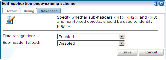
You can use the Time recognition menu to control whether non-forced objects are used to identify the page. Consider the example shown in Figure 6-7.
In this case, there are three non-forced objects (home.jsp, sub.jsp, and down.jsp) that could potentially be used for page identification. If the Disabled option is specified for the Time recognition menu (the default), only the first (home.jsp) object would be identified as a page if detected within one second of the last hit. However, if enabled, each of the three non-forced objects (such as jsp) would be identified as separate pages, regardless of detection time considerations. For further information on forced objects, see Section D.4.2, "Forced Objects".
If you selected the HTML title page-naming scheme, the text found within the page's <title> tag is used to identify the page. Potentially, if not found, you may want the sub-headings <H1>, <H2>, and <H3> to be used. Therefore, you can use the sub-header fallback menu to control this facility. By default, the sub-headers are not used (Disabled).
If you selected any of the client request-based schemes (such as URL base), and click the Advanced tab, the dialog shown in Figure 6-8 appears.
Figure 6-8 Edit Application Page-Naming Scheme
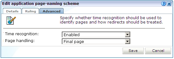
You can use the Page handling menu to specify how redirects within a URL should be handled. The following options are available:
Final page: specifies that only the final page URL should be used to determine the page name. This is the default.
Redirect naming: specifies that the page should be identified using the information available from the redirect in front of the final page. If not available, the final page's information is used.
Redirect becomes page: specifies that the redirect will become the actual identified page. Note that the first redirect is used for page creation, and all subsequent redirects become objects on the created page. It is strongly recommended that you only select this option if you clearly understand its consequences for application reporting.
Note:
Be aware that the Full session replay facility (described in Section 3.10, "Working With the Diagnostics Facility") and error reporting may not function correctly if page names have been derived from redirects.Each application definition requires you to specify the page-naming scheme to be used. This scheme can be extended through the use of the ruling facility. This allows you to specify additional matching rules that should be used to refine the selected scheme. The matching rules are based on the specified page-naming scheme. Note that the ruling facility is only available in combination with automatic (and not manual) page-naming schemes.
Note:
Because of the complex nature of ruling, it is recommended this facility is only used by users with a sound understanding of their specified page-naming scheme. In addition, the selected application's underlying structure should be clearly understood.To specify the use of ruling for a selected application, do the following:
After you have initially defined your application (as described earlier), click the page-naming scheme setting shown in Figure 6-5. If you selected any scheme other than Manual, the dialog shown in Figure 6-9 appears.
Figure 6-9 Edit Application Page-Naming Scheme Dialog
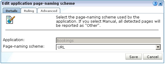
Click the Ruling tab to specify the rules to be used, and the order in which they should be evaluated. The dialog shown in Figure 6-10 appears.
Use this dialog to define new rules or delete existing ones. You can also use the context menu under each rule to modify the order in which they are applied. Click the Add new matching rule item to define new matching rules. The dialog shown in Figure 6-11 appears.
Specify the following components for the rule:
Input value: specifies the structure of the expected scheme (such as URL or page tagging). Essentially, it provides a template for interpreting the received scheme.
Search expression: specifies a definition of the scheme that should be matched. Typically, this is expressed in terms of required parameters, and the sequences that should comprise them.
Page group: specifies how the page group is identified from the received scheme. Note if this is not specified, the page group is assigned the page name.
Page name: specifies how the page name is identified from the received scheme.
After specifying the rule's components, you can click the Check rule button to verify that the defined rule is consistent with the specified validation value. Note that the result window can be expanded in order to view a summary of the matched placeholders. An example is shown in Figure 6-12.
When ready, click Save. You are returned to the dialog shown in Figure 6-10.
After defining all required rules, you can click the « Check rules » item to verify all defined rules against their validation values. Each validation value should be relevant to its corresponding rule. After verification, the icon shown beside each rule indicates its status. For rules that were not successfully verified, additional information is available via mouseover or hover box. Consider the example shown in Figure 6-13.
The first rule is consistent with its defined validation value, and is successfully verified. However, the second rule is extremely generic, and you are warned that multiple validation rules could match this rule. In fact, it is so generic that no subsequent rule could be applied because its associated validation value has already been successfully applied. That is, the third rule will never be reached. That is why a error is reported on the third rule, and not the second. However, if the second rule was moved down to become the last rule, then the three rules would be successfully verified.
Although it is possible to save ruling definitions with reported errors, it is strongly recommended that you resolve any issues before saving a ruling definition. When ready, click Save. Any changes you make to a ruling definition take effect within five minutes.
Be aware that URL matching is case sensitive, and URLS (after matching) are converted to lower case. Matched slashes are replaced by spaces in the page name after ruling.
Ruling for User Identification
In addition to page-naming schemes, the ruling facility is also available within user identification schemes. These are fully described in Section 6.2.10, "Defining User Identification".
The use of ruling for user identification is equivalent to that described above for page naming, except that you specify how the user ID is identified from the selected scheme, and page group identification is not supported.
Consider the following case. The specified user-identification scheme is based on cookies, and each cookie has the following structure:
ORA_UCM_INFO=5~DVJ88287~John~Doe~john.doe@myshop.com~USA~en~33~44~5~~1;
You want user identification to be based only on the E-mail address portion of the cookie. In this case, you could specify the following:
Search expression: %~%~%~%~%~%User ID: %5
The validation value could be specified using the example cookie shown above, or some other example cookie with the same structure.
Identifying Page Groups Within Rules
When using the advanced ruling facility with a page-naming scheme whose source includes a page group, you should ensure that the group value is correctly identified. In the case of a URL page-naming scheme whose source is "myhost.com/myshop/menswear/catalog/basket.jsp", it is internally converted to the structure "myshop|menswear/catalog". This then needs to be transformed for correct reporting as follows:
Source: %\%7C%/%Group: %1 Name: %2
In the source specification, the separator (|) between group and page name is specified as \%7C, and is an encoded pipe character. Note that the slash characters within URL structures can be used in ruling. Matched slashes are replaced by spaces in the reported groups and names after ruling.
In addition to the use of parameters, the elements shown in Table 6-1 can also be used in URL matching rules.
Table 6-1 Advanced Search Constructions
| Usage | Description |
|---|---|
|
|
Match zero or more characters and fill one placeholder. Allowed placeholders are %1 - %9. |
|
|
Find one value corresponding to any of the supplied name(s) in the URL argument, and fill one each for the original and matched placeholders. |
|
|
Find all values corresponding to the supplied name(s) in the URL argument, and fill one parameter placeholder for the original and specified number of placeholders. |
|
|
Find zero or more values corresponding to the supplied name(s) in the URL argument, and fill one placeholder for the original and specified number of placeholders. |
|
|
Find the specified number of characters. |
|
|
Find directory path of the URL, and fill one placeholder. |
|
|
Find file name path of the URL without the file extension, and fill one placeholder. |
|
|
Find domain part of URL, and fill three placeholders (for example, |
|
|
Match until one of the following characters is matched, and fill one placeholder. |
|
|
Match until a character is found that does not match the specified list of characters. |
Note that special characters (%, \, |, !, and ~) must be preceded with a backslash if they should be interpreted literally. For example, \% specifies a literal % character, rather than a parameter. In addition, special characters after the % character (^, &, [, and ]) also need to be escaped. Be aware that a maximum of nine placeholders can be specified.
Search value: %[h]/%/%/%/%?%
Page group: %6 (electronics)
Page name: %7 (tv821)
URL (for checking): www.mydomain.co.uk/shop/catalog/electronics/tv821?params=all
Search value: %[h]/%[&shop_cat]
Page group: %2 (pcShop)
page name: %5 (Cables)
URL (for checking): www.pcShop.com/home/applications/catalog?cust_id=123&shop_cat=Cables
Search value: %[h]/cart:%[c9]/articleid:%[c9]/%
Page group: %4 (00000ABCD)
Page name: %5 (000018201)
URL (for checking): www.myshop.com/cart:00000ABCD/articleid:000018201/shop.jsp?params=all
By default, pages that have been identified as belonging to an application through its URL definition, but for which no classified name has been found, are discarded and not reported. However, if you want these unclassified pages to be reported in Data Browser groups, use the Report unclassified pages check box within the Pages section of the application overview shown in Figure 6-14.
Figure 6-14 Application Page Configuration Section
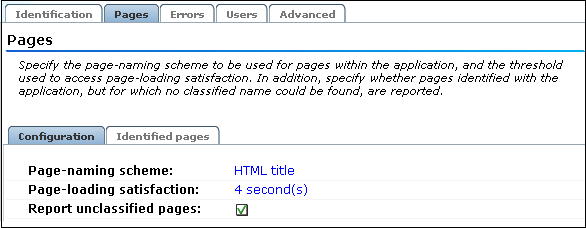
Because page identification is a time-based activity, it is possible that references to objects not booked as objects are incorrectly identified as unclassified pages. For this reason, it is recommended that you only enable the reporting of unclassified pages for testing purposes. Thereafter, you can disable it again, and define the identified problems pages manually. Note unclassified pages are reported in the appropriate Data Browser group under the category "other".
Note that monitored service tests can also be converted into RUEI user flows. This is fully described in Section 6.6.6, "Converting Service Test Sessions into User Flows".
You can use the Report service test traffic check box within the Advanced section to specify whether service test traffic configured within Oracle Enterprise Manager Grid Control for a selected application should be reported within RUEI. By default, reporting is disabled. For further information on the use of this facility, see Section 3.2.6, "Oracle Enterprise Manager Service Test Monitoring".
When reporting on user visits, the client IP address is, by default, fetched from the IP packet. However, when the RUEI system is placed in front of a NAT device, it may be more useful for the client IP address to be obtained from a specific HTTP request header. This is fully explained in Appendix O, "Monitoring NATed Traffic".
As explained earlier, each page within RUEI has the form application » group » name. Automatically detected pages are assigned their group and page names based on the directory structure within the URL. The first directory in the URL is assigned to the group name, and the remaining sub-directories are assigned to the page name. Note that the domain part is not used in the assigned name. Note this only applies to applications defined with the URL base, directory, or full page-naming schemes.
For example, the page URL http://MyShop.nl/catalog/menswear/sale.html for the application "Clothing" would generate the RUEI page name Clothing » catalog » menswear sale. Note that slashes within the directory structure are converted to spaces.
If there are no sub-directories in the URL, then the default group "home" is assigned to the page. For example, the URL http://MyShop.nl/sale.html in the application Clothing is assigned the page name clothing » home » sale.
Once you have defined your application, you can modify its associated page-naming scheme by clicking it and selecting a new scheme, as described earlier in this section.
Within the Identification section, you can click « Add new filter » to specify additional filters for the pages that should be associated with the application. You can also modify an existing filter definition by clicking it. In each case, you can select from the same filters as shown in Figure 6-2. The application overview is updated to reflect your additions or modifications.
In order to assess the user's experience when viewing application pages in a session, RUEI assigns a satisfaction level for each page. These are:
Satisfactory: the page loads in the user browser within a specified threshold. This threshold is the page loading satisfaction threshold. For example, the page should load within five seconds.
Tolerable: the page takes less than four times the specified threshold period to load.
Frustrating: the page takes more than four times the specified threshold to load.
An example page load satisfaction report is shown in Figure 6-15.
Figure 6-15 Page Loading Satisfaction Report
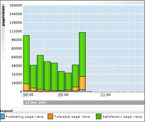
As stated above, this assessment is based on a threshold within which pages would normally be expected to load. This threshold can be modified to fine tune the reported page load satisfaction within the Data Browser. Do the following:
Select the required application, click the Pages section, and click the currently defined Page-loading satisfaction setting. The dialog shown in Figure 6-16 appears.
Figure 6-16 Page Load Satisfaction Time Dialog
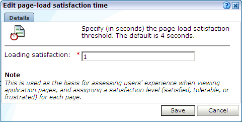
Specify the duration (in seconds) within which page loads would normally be expected to be completed. The default is 4 seconds. When ready, click Save. Any change you specify takes effect immediately.
Sometimes you want to detect strings that appear within pages, and have them reported as application errors. For example, the message "Selected item is out of stock". These functional errors differ from system errors (such as Web server or network errors) in that they are based on page content, rather than a return code, and are specific to a configured application.
Note that all pages within the selected application are searched for the specified error string. It is not possible to limit the search to specific pages, as it is with page content checks. Displayed page texts that match your specified error text strings are reported with the page content result "error string: error search string". An example of a functional error report is shown in Figure 6-17.
To define a functional error string, do the following:
Select Configuration, then Applications, and select the required application. The Application overview (similar to the one shown in Figure 6-5) appears. Click the Errors section, and then the Errors tabs. The currently defined functional errors are displayed. Click « Add new functional error » to define a new error, or click an existing one to modify it. The dialog shown in Figure 6-18 appears.
Use the Search type menu to specify the scope of the search. This can be the request or response header or content. The search can be based upon a literal search string, or an XPath expression. In the case of an XPath expression, only the request or response header can be searched.
Use the String field to specify the literal search string. Note that the use of wildcards is not supported, and all specified characters are treated as literals. Alternatively, use the XPath search field to specify the XPath expression that should be used. More information about the use of XPath queries is available in Appendix F, "Working with XPath Queries".
When ready, click Save. Any changes you make will take effect within 5 minutes.
Instead of separately defining each functional error that you want to be monitored, you can import a file containing a list of predefined application errors. Do the following:
Select Configuration, then Applications, and select the required application. The Application overview (similar to the one shown in Figure 6-5) appears. Click the Errors tab, and then the Errors tabs. Click « Upload list ». The dialog shown in Figure 6-19 appears.
Figure 6-19 Upload Functional Errors Dialog
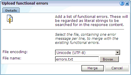
Use the Browse button to locate and select the required file. Optionally, use the File encoding menu to specify the file's character encoding. For more information on international character set support, see Appendix G, "Working With National Language Support". If an unsupported encoding is encountered, or the transcoding fails, an error is reported.
The uploaded file must contain one error message per line, and there should be no blank lines in the file. Be aware that these messages will be regarded as literal strings to be searched for in the response content. When ready, click Merge.
Optionally, you can also define a set of translations for each unique error string. For example, you could define the translations for Oracle database errors shown in Table 6-2.
Table 6-2 Example Error String Translations
| Error string | Translation |
|---|---|
|
|
An attempt was made to acquire a DDL lock that is already locked. |
|
|
The number of temporary tables equals or exceeds the number of temporary table locks. |
|
|
DB_BLOCK_SIZE initialization parameter is wrong for the database being mounted. |
|
|
The value of the DB_FILES initialization parameter was exceeded. |
|
|
User flows deadlocked one another while waiting for resources. |
|
|
The shared instance being started is using DML locks, and the running instances are not, or vice-versa. |
|
|
The instance was started with DML_LOCKS = 0, and the statement being executed needs a full-table lock (S, X, or SSX). |
|
|
The number of log files specified exceeded the maximum number of log files supported in this release. |
To define an error translation, do the following:
Select Configuration, then Applications, and select the required application. The Application overview (similar to the one shown in Figure 6-5) appears. Click the Errors section, and then the Error translations tab. The currently defined error translations are displayed. Click « Add new translation » to define a new translation, or click an existing one to modify it. The dialog shown in Figure 6-20 appears.
Specify the required source value and its translation. When ready, click Save.
When working with a large number of translations, you can use the Search field to quickly locate a required translation. The search facility uses partial matching. The use of wildcards is not supported, and all characters are treated as literals. When ready, click Go.
Instead of separately defining each translation, you can click the « Upload list » item to import a file containing a list of translations. The dialog shown in Figure 6-21 appears.
Figure 6-21 Upload Error Translations Dialog
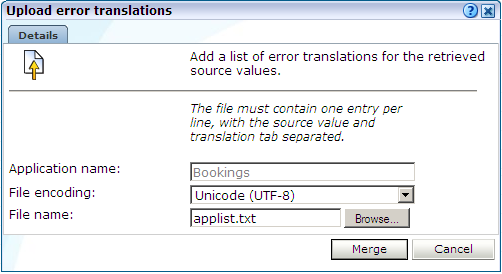
Specify the name of the translation file. Optionally, use the File encoding menu to specify the file's character encoding. For more information on international character set support, see Appendix G, "Working With National Language Support". If an unsupported encoding is encountered, or the transcoding fails, an error is reported.
The file may only contain one translation per line, with source values and translations tab separated. When ready, click Merge.
It can be extremely useful for content errors to be reported alongside standard return codes, such as 404 or 500. This would enable you to provide additional information about the context of the error in order to facilitate troubleshooting. However, this is not default reporting behavior.
As explained in Section 3.2.3, "Page Delivery Dimension", if a page experienced several types of errors (for example, both a server error and a content error), the page error is not reported multiple times. Instead, it is reported based on the following prioritization: Web site, server, network, and content.
To specify that standard returns should be reported with additional explanations, do the following:
Select Configuration, then Applications, and select the required application. The Application overview (similar to the one shown in Figure 6-5) appears. Click the Errors section, and then the Advanced tab.
Check the Add additional explanations check box to specify that a defined translation (if available) should be appended to the reported return codes. By default, such translations are not appended.
Click the Error translations tab, and a define the required explanation. The procedure to do this is described in Section 6.2.9.3, "Defining Translations for Functional Errors". For example:
Source value: 1001 Translation: Database connection could not be established
where the specified source value represents an internal application code for a failed database connection.
An example of enhanced page delivery details is shown in Figure 6-22.
Figure 6-22 Example Additional Page Delivery Details

Within RUEI, newly created applications are automatically configured to have user identification based on the HTTP Authorization field and the Common Name (CN) portion of SSL client certificate (when available). This is shown in Figure 6-23.
Figure 6-23 Application User Identification Scheme
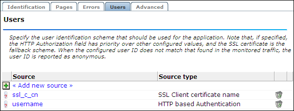
However, you can also configure the application's user identification scheme in terms of URLs, cookies, request or response headers, XPath expressions, custom tag or responses, or OAM user tracking (see Section 6.3, "Monitoring OAM-Based Traffic"). Note that the HTTP Authorization field has priority over other configured values, and that the SSL certificate is the fallback scheme. When the configured user ID does not match that found in the monitored traffic, the user ID is reported as Anonymous.
Configuring an Application's User Identification Scheme
To configure an application's user identification scheme, do the following:
Select the required application, and click the Users section.
Click the « Add new source » item. The dialog shown in Figure 6-24 appears.
Figure 6-24 Add New User Id Source Dialog
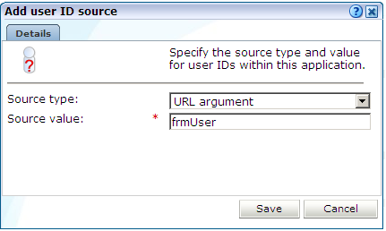
Use the Search type menu to specify the user identification mechanism. This can be specified in terms of a literal search string or an XPath expression. Be aware of the following:
In the case of a literal search string, you can specify whether the request or response header should be searched.
In the case of an XPath expression, you can specify whether the request or response should be searched. More information about using XPath queries is available in Appendix F, "Working with XPath Queries".
In the case of a cookie, you need to specify the name of the cookie. Note that if hashing is specified for the selected cookie, or as the default cookie masking action, the cookie's uniqueness is preserved, but not its original value. This is fully explained in Section 8.4, "Masking User Information".
In the case of a URL argument, the name of the argument must be specified.
In the case of OAM-based traffic, see Section 6.3, "Monitoring OAM-Based Traffic" for more information.
In the case of a custom pattern, you must specify a start string and (optionally) an end string to delimit the searched content. Note that the use of wildcard characters is not supported, and all specified characters are treated as literals. In addition, besides any specified end string, the search will never extend beyond a new line.
In the case of a custom tag, you must specify the name in the name=value pair from which the user ID will be retrieved.
As explained earlier, if the HTTP-based authentication is specified, this takes priority over any other defined identification scheme. In addition, if the SSL client certificate is specified, this is the fallback scheme.
When ready, click Save.
Note:
You can check the effect your user identification definition has by viewing the XLS User Information report in the Clients category. For more information on reports, see Chapter 2, "Working With Reports".See Appendix G, "Working With National Language Support" for a detailed discussion of the implications for identification when working with international character sets.
The structure of the pages detected for an application are shown in the application overview on the left-hand side of the window. An example is shown in Figure 6-25.
Figure 6-25 Example Application Page Structure
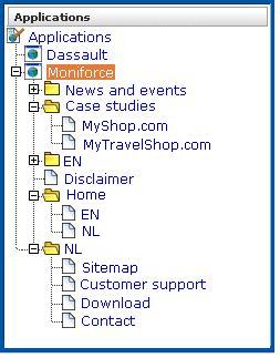
Potentially, an application could have a very large number of pages associated with it. Indeed, far too many to be easily readable in the structure shown in Figure 6-25. For this reason, the structure view is restricted to those pages that have some Point of Interest (POI) associated with them. This could include the fact that the page is featured in a report, is defined as a key page, is manually named, or is part of a monitored KPI. The View menu shown in Figure 6-26 allows you to control which type of pages are displayed in the structure overview.
The following options are available:
All: list all application pages.
Report pages: list only pages that have been specified as report filters (Section 2.5, "Using Report Filters").
Checked pages: list only pages for which content checks have been defined (see Section 6.2.14, "Specifying Page Content Checks").
Manually named pages: list only pages that have been manually defined (see Section 6.2.15, "Manually Identifying Pages").
Key pages: list only pages that have defined as key pages (see Section 6.2.13, "Tracking Page Usage").
By drilling down through the application page categories, you can locate specific pages. However, if you are working with an application with a large number of pages, it may be more convenient for you to use the page search facility. Do the following:
Select the application you want to search. Select the Pages section, and click the Identified pages tab.
Specify the search profile you want to use to locate the required page(s). Note that the search is restricted to the current application, and page names have the structure application » group » name. The search facility will try to match any search pattern you specify either as a full match or as a substring. Hence, the search pattern "home" would match occurrences of this string or any substring in the application, group, or page names. When ready, click Go. An example results listing is shown in Figure 6-27.
Figure 6-27 Page Search and Results Dialog
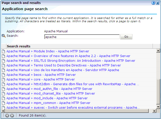
The search results are shown in the lower part of the dialog. Click a matched page to open it. Use the Backward and Forward buttons to scroll between multiple pages of results. In addition, you can use the View menu (described in Section 6.2.11, "Viewing the Application Page Structure") to limit the displayed list to a certain criteria, such as pages used in reports.
Note:
The scope of the search includes both pages that have already been detected, and undetected pages that appear in reports and user flows.Information about each page detected for an application is available through the page Analysis window. An example is shown in Figure 6-28.
The following tabs are available within this window:
Identification: specifies the page identification scheme (manual or automatic), and the conditions used to identify it.
Content check: specifies if content search strings have been defined for the page. This is described in Section 6.2.14, "Specifying Page Content Checks".
Reporting: lists the reports in which this page appears. Reports are described in Chapter 2, "Working With Reports."
Monitoring: list the KPIs in which this page appears. See Section 5.2, "Defining KPIs and SLAs" for more information about the procedure for defining KPIs.
Use the Key page check box in Figure 6-28 to define a page as a key page.
Key pages are monitored Web pages that receive special attention. Typically, these are pages in which you have particular interest. For example, your organization's home page, or a series of pages in a user flow (such as placing an order). For these pages, additional information is recorded. This includes client information (such as the ISP, the country of origin, and so on), and the client browser information (such as operating system, browser version, and so on).
Sometimes you want to monitor a specific page for the occurrence of a specific text string. For example, your Web application has an Order page, and at the end of a successful sale, the text string "Thank you for shopping with us" appears on the page. You can define a page content check that looks for this string on the required page. Note that if the specified text string is not found on the page, the page content check returns "configured string not found".
To define a page content check, do the following:
Select Configuration, then Applications, then Applications, and then select the required application page. The Page analysis window (shown in Figure 6-28) appears.
Click the Content check tab, and click Add check. The dialog shown in Figure 6-29 appears.
Specify whether the search should use a literal search string or an XPath expression, and whether the server response or client request should be searched. In the case of an XPath expression, you can also specify an exact value to search for in either the client and server response content. More information about using XPath queries is available in Appendix F, "Working with XPath Queries". When ready, click Save.
In addition to identifying pages through applications, you can also define pages manually. Note that manually identified pages take precedence over pages identified automatically through applications. This facility is very useful in the case of sub pages that cannot be identified automatically, and to which you want to assign a different name. Manually identified pages are created by selecting an existing page to be the basis for the new page.
To manually identify pages, you can either define the new page from scratch, or use an existing page (automatically detected or manually defined) as the basis for the new page.
To define a page, do the following:
To define the page from scratch, select the required application, and click the New page button. To use an existing page as a basis for the new page, select the required application page, and click the New page (based on current) button. In either case, the dialog shown in Figure 6-30 appears.
Note:
If the required page is not visible in the application overview for you to select, locate it using the Search button (described in Section 6.2.12, "Locating Page Details").Use this dialog to specify the conditions that must be met for the page to receive the assigned name. These conditions can be defined in terms of the page's partial or exact URL, content, domain, or arguments. An XPath expression can also be specified. Click Add condition for each required condition.
Note that when specifying an exact URL (for example, http://www.oracle.com/contact.html) the domain and remaining URL structure are automatically assigned to the page conditions. For example, within the "Find in domain" option (oracle.com) and the "Find exact URL" option (/contact.html).
As you specify additional conditions, these are shown in the dialog. All specified conditions must be met for a match to be made. Note that conditions shown in blue can be removed by clicking them, while conditions shown in black cannot be removed. You must specify at least one condition for page identification. When ready, click Next. The dialog shown in Figure 6-31 appears.
Use this dialog to specify a group and name for the page. When ready, click Finish.
The new page's details are shown in a window similar to the one shown in Figure 6-25. You can use this window to track the page's detection, and modify its definition.
The URL diagnostics group (described in Section 3.2.4, "The URL Diagnostics Group") allows you to view the functional URLs reported for hits within applications. These can be customized on application level to meet your specific requirements.
The use of URL diagnostics can provide valuable insight into application issues. For example, if a certain application is experiencing unusually large load times, you can quickly identify the specific problem object or the server responsible. Moreover, when coupled with the Session Diagnostics facility (see Section 3.10, "Working With the Diagnostics Facility"), this functionality provides extremely powerful root-cause analysis of application issues.
To specify the URL diagnostics reporting scheme that should be used for a selected application, do the following:
Select Configuration, then Applications, and select the required application. The Application overview (similar to the one shown in Figure 6-5) appears. Click the Advanced section, and click the URL diagnostics tab. The currently defined URL patterns used to specify the scope of the monitored URLs are displayed. Click « Add new URL pattern » to define a new pattern matching scheme, or click an existing one to modify it. A dialog similar to the one shown in Figure 6-32 appears.
Use the URL match type menu to specify whether the schemes you are about to define should be applied to all application URLs, or only to specific URLs. In the case of the later, you need to specify the URL structures that should be reported for the application within the URL diagnostics group. These should be defined as URL patterns that, when matched to detected URLs, will be reported. While the use of a wildcard characters (*) is supported, all other specified characters are interpreted as literals. Note that if no URL structures are defined, the application's associated hits are not reported within the URL diagnostics group.
You can also specify the parts (or components) of the detected URL structures that should be reported. Alternatively, you can the restrict the reported URL to specific arguments. In either case, click the « Add URL argument/component » item. A dialog similar to the one shown in Figure 6-33 appears.
Use the Scheme type menu to specify if a matched URL should be limited to a specific parameter or component when reported. In the case of a parameter, you must specify the parameter name to be reported. In the case of a component, you must specify the component of the matched URL to be isolated, and use the Part menu to specify the part of it that should be reported. The number of options available is equivalent to the number of wildcards (*) specified in the URL component field.
For example, consider the component definition shown in Figure 6-34.
Figure 6-34 Example URL Diagnostics Component Definition

In this case, only the part after */MyShop/catalog/ would be reported. Note that part parameters are matched to the wildcards specified in the Value definition. For example, the specified value */session=*/* contains three wildcards, and so the matched URL is regarded as having three logical parts. Note that a maximum of nine wildcards can be specified within an URL diagnostics definition.
When ready, click Save. You are returned to the dialog shown in Figure 6-32.
Review the parameter and component definitions for the application. When ready, click Save. Any matched URL patterns are reported within the URL diagnostics group after 5 minutes.
Note that forced objects (described in Section D.4.2, "Forced Objects") are automatically stripped from reported URLs. In addition, it is recommended that you configure your application definitions to exclude the reporting of session parameters and static-based objects (such as images). This is in order to prevent diagnostics information becoming too long and its possible truncation.
Application pages viewed through the Session Diagnostics replay facility can contain inline JavaScript code. Typically, this code is used to perform checks. For example, by connection to a specified server to determine if a session has expired. These checks, as well as other JavaScript functionality, can present problems when viewing their associated pages through the Replay facility.
For this reason, the application configuration facility allows you to specify how execution of inline JavaScript code should be handled within the Replay viewer (described in Section 3.10, "Working With the Diagnostics Facility"). JavaScript execution can be completely disabled, or you can specify that specific functions or files should be replaced during page replay.
To define the JavaScript execution rules that should be used when replaying an application's pages, do the following:
Select Configuration, then Applications, then Applications, and then select the required application. The Application overview (similar to the one shown in Figure 6-5) appears. Click the Advanced section, and then the JavaScript replay tab. The currently defined execution rules are displayed. A dialog similar to one shown in Figure 6-35 appears.
Use the Disable all JavaScript execution check box to specify whether all JavaScript code within the selected application's pages should be disabled when replayed within the Replay facility. Note that if checked, any existing execution rules are ignored, and it is not possible to define new ones. By default, it is checked.
Click « Add new rule » to define a new execution rule, or click an existing one to modify it. Note that this facility is only available if the Disable All JavaScript execution check box is unchecked. A dialog similar to the one shown in Figure 6-36 appears.
Use the Rule type menu to specify the type of execution rule you want to define. You can select the following options:
Replace function: specifies that a named JavaScript function should be removed and, optionally, substituted for a return code at execution. For example, a function that checks whether a cookie is still valid could be replaced during replay with the returned value "OK".
The definition for the specified function must appear in the page's inline code. It is not possible to replace external functions. Note that the JavaScript code is only replaced in the rendered browser page, and not in the replayed page's contents (as reported within the HTTP content facility).
Be aware that if the function definition contains any comment between the function syntax and the function name, replacement will fail. For example, the following construction would fail:
function
/* some comment */
myfunction ( url ) {
.....}
If your application pages include references to external functions, you can replace them by uploading files containing the modified function definitions. This is described below.
Replace file: specifies that a named file containing JavaScript code should be replaced with an alternative file. For example, a file containing validation routines might be replaced with a simplified version for replay purposes. If this option is selected, the Source name field must specify the name and extension of the file to be replaced. These must be the same as those specified within the associated script element. For example, consider the following file reference:
<script type="text/javascript" src="public/scripts/checks.js"></script>
Here, the file name checks.js must be specified.
Use the Replacement file field to specify the substitute file. This must have the file extension .js, and the MIME type "text". The file is uploaded to the /opt/ruei/gui/upload/ directory on the Reporter system.
When ready, click Save. Any changes you make to the defined application replay rules are applied immediately.
The replacement .js file is uploaded to the /opt/ruei/gui/upload directory on the Reporter system. Note that, if necessary, you can modify the contents of the replacement file by selecting the appropriate rule, and either uploading a modified version of the original file, or specifying a completely new file. In either case, the contents of the original file are overwritten with the newly uploaded file. When a rule is deleted, any file uploaded for it is automatically also deleted.
Be aware that, if an application contains multiple rules referring to the same file, only one version of the file is held on the Reporter file system, and this is always the latest version to be uploaded. The file is only removed from the file system when all rules that use it have also be been deleted.
Quite often the same JavaScript files are used across multiple applications. Be aware that each replacement file specified for an application represents a unique file. This is true even if the same file name is specified across multiple applications. For example, imagine that three applications, A, B, and C, all have the replacement file mychecks.js specified for them. In this case, three versions of the mychecks.js file are maintained by RUEI. Any changes made to one particular file only apply to its associated application, and not to any other applications.
RUEI can be configured to identify user IDs within Oracle Access Manager (OAM) traffic. OAM version 10.1.4.x (or higher) is supported. In order to monitor OAM-based traffic, do the following:
Select the required application, and click the Users section.
Click the « Add new source » item. The dialog shown in Figure 6-24 appears.
Within the Search type menu, select the "Oracle Access Manager" option.
Within the Source value field, specify the name of cookie used to track user identification within the monitored OAM-based traffic. By default, this ObSSOcookie. When ready, click Save. If your OAM server uses a customized cookie implementation, you should consult your OAM administrator. Information on the customization of OAM cookies is available from the Oracle Access Manager Administrator Guide.
Select Configuration, then Applications, and then Session tracking. The currently defined cookie settings are displayed. An example is shown in Figure 7-1.
Click « Add new cookie ». The dialog shown in Figure 7-2 appears.
Within the Cookie type menu, select the "OAM" option.
Within the Cookie name field, specify the cookie used to track user identification within the monitored OAM-based traffic. By default, this is the "ObSSOcookie". When ready, click Save.
The procedure to configure your OAM server to work with RUEI is described in the Oracle Real User Experience Installation Guide.
Reporting of OAM-Based Traffic
The reporting of user IDs within the Data Browser is based on Distinguished Name (DN). An example is shown in Figure 6-37.
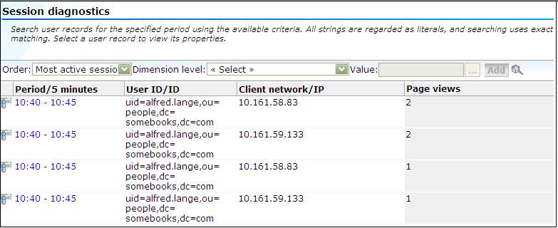
Figure 6-37 Example of Reported OAM Traffic
Single sign-on (SSO) is a method of access control that enables a user to log in once and gain access to the resources of multiple software systems without being prompted to log in again. Because different applications and resources support different authentication mechanisms, SSO has to internally translate and store different credentials compared to what is used for initial authentication. SSO offers the following benefits:
Reduces password fatigue from different user name and password combinations.
Reduces time spent re-entering passwords for the same identity.
Reduces IT costs by lowering the number of IT help desk password-related calls.
SSO uses centralized authentication servers that all other applications and systems utilize for authentication purposes, and combines this with techniques to ensure that users are not actively required to enter their credentials more than once.
In order to facilitate the correct monitoring of SSO-enabled applications, you need to configure the authentication server(s) used within your environment. This is done through the creation of an SSO profile.
SSO servers manage user profiles and provide a login page to authenticated users. Applications then interact with SSO servers to validate temporary tokens. Figure 6-38 illustrates how application authentication works when enabled by an SSO server.
Figure 6-38 Authentication Flow Within SSO-Enabled Application Traffic
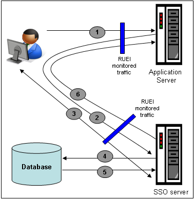
The authentication flow shown in Figure 6-38 takes the following sequence:
The user attempts to access a protected URL. The application server checks for the existence of an authentication cookie for the requested application. If found, it means that the user is already logged on, and no further authentication is required.
The user is re-directed by the application server to the SSO server. The application server also provides an application URL to the SSO server so that it knows where to go after user logon. Note the SSO server also checks whether the user is already authenticated (by another application) by validating any existing authentication cookie.
In the event the user is not recognized based on an existing authentication cookie, the SSO server requests credentials from the user via the login page, and these are specified by the user in a user name and password combination.
The user's credentials are verified against their entry in the SSO server database. Once validated, the authentication is preserved by an SSO cookie. The name of this cookie must be specified when creating a SSO profile.
The SSO server fetches the user's attributes. The attributes that are actually fetched are implementation-specific, and are not relevant to RUEI.
The SSO server passes the fetched attributes to the partner application server, using the URL provided to it in step 2. Note that a token argument is added to this URL. The name of this token argument must be specified when creating SSO profiles. The application server will probably also issue its own cookie to the user. This is configured as part of the application or suite definition.
Finally, note the network lines over which steps 1, 2, and 5 pass must be within the scope of RUEI monitored traffic.
It is important to understand that SSO profiles and applications, although closely related, are reported as separate entities within RUEI. For this reason, SSO profile and application definitions should be mutually exclusive. That is, each should be based on separate domains and cookies. Otherwise, the monitored traffic is reported as application-related traffic, and the potential benefits to enhanced reporting are not realized.
To define a SSO profile, do the following:
Select Configuration, the Applications, then Single Sign-On, and Click New SSO profile. The dialog shown in Figure 6-39 appears.
Specify a name for the SSO profile. This must be unique across suites, services, applications, and SSO profiles. Note that SSO profiles cannot be renamed later.
Use the remaining fields to specify the scope of the SSO profile. This is defined in terms of partial page URLs. Note that as you enter this information, you can see the effect of your definition through the Filter preview column.
Note:
It is advised that filter definitions be mutually exclusive across SSO profiles, applications, suites, and services. Otherwise, this can lead to unpredictable results. See Section 7.6, "Controlling Rule Ordering Within RUEI" for information about how you can influence the order in which matching rules are applied.The highest level filter is the domain. You can specify a partial URL instead of, or to refine, a domain. It is not possible to specify a profile name and leave all other fields blank. That is, a blank filter. Note that a wildcard character (*) cannot be specified within the Find Port field, and network traffic arriving on a non-standard port (that is, other than ports 80/443), is not associated with the SSO profile unless the port number is explicitly stated. Only one port number can be specified. If you want to specify additional ports, these should be specified as additional filters after the new SSO profile has been created.
Be aware that while the use of a wildcard character is supported, all other specified characters are interpreted as literals. Note it is not possible to specify the wildcard character and no other information for domain and URL combinations. See Section 7.6, "Controlling Rule Ordering Within RUEI" for information about how you can control the order in which filters are applied.
When ready, click Next. The dialog shown in Figure 6-40 appears.
Figure 6-40 Single Sign-On Server Information Dialog
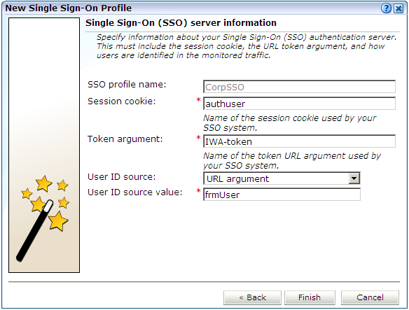
Use this dialog to specify information about the SSO authentication server you are using. You need to specify the session cookie name, the URL argument which contains the authentication token, and how users are identified in the monitored traffic. Normally, this is defined in terms of a URL argument and value. However, it can also be specified in terms of cookies, request or response headers, or XPath expressions.
When ready, click Finish. An overview of the SSO profile definition you have specified is displayed. An example is shown in Figure 6-41.
This overview provides a summary of the defined SSO profile and allows you, if necessary, to modify its definition. This is explained in the following section.
You can check the effect your user identification definition has by viewing the XLS User Information report in the Clients category. For more information on reports, see Chapter 2, "Working With Reports".
After defining an SSO profile, you can modify it via its overview. The following tabs are available:
Identification: specifies the scope of the SSO server in terms of one or more partial page URL matches. Pages are assigned to the SSO server when a defined filter matches a page's URL. To add a new filter, click Add new filter. Click an existing filter to modify it. A dialog similar to the one shown in Figure 6-42 appears.
Figure 6-42 Edit SSO Profile Filter Dialog
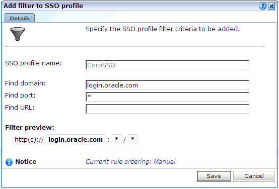
The note at the bottom of the dialog indicates the current rule ordering scheme. This is explained in Section 7.6, "Controlling Rule Ordering Within RUEI".
Configuration: specifies the authentication token and cookie used.
Users: specifies how user IDs are identified within the application. When not defined, the SSL client certificate is used (when available).
When verifying the correct operation and reporting of your SSO-enabled applications, the important aspect to inspect is the correct identification of users. It is recommended that you regularly review the reporting of within the Data Browser (All sessions > User Id > Sessions and page views). For example, an unexpectedly high level of unidentified (anonymous) users.
Also, you should verify that URLs within SSO-enabled applications are not reported within application-related data. This can indicate that there is a problem.
As explained earlier, page identification within RUEI is based on applications. However, if these applications are based on certain Oracle Enterprise architectures (such as Oracle E-Business Suite, Siebel, and WebLogic Portal), then a fourth level, suite, is introduced. A suite is essentially a collection of applications, and Web pages associated with these suites have the structure suite » application » group » page.
If you are using any of the any of the currently supported Oracle Enterprise architectures within your monitored environment, it is strongly recommended that you make use of this facility. It not only saves you time in defining your applications, and makes applications within suites more compatible, but also ensures that these architectures are monitored correctly.
To define a suite instance, do the following:
Select Configuration, then Applications, and then Suites from the menu structure shown in Figure 6-43.
Click New suite. The dialog shown in Figure 6-44 appears.
Specify a name for the suite. The name must be unique across suites, services, SSO profiles, and applications, and is restricted to a maximum of six characters. Note that suite instances cannot be renamed later.
Use the remaining fields to specify the scope of the suite. This is defined in terms of partial page URLs. The use of these filter criteria is the same as described in Section 6.2, "Defining Applications". Note that as you enter this information, you can see the effect of your definition through the Filter preview column. The use of blank filters is not permitted. Note that a wildcard character (*) cannot be specified within the Find port field, and network traffic arriving on a non-standard port (that is, ports 80/443), is not associated with the suite instance. Only one port number can be explicitly specified. If more are required, they should be configured as additional filters. Note it is not possible to specify the wildcard character and no other information for domain name and URL argument combinations. When ready, click Next. The dialog shown in Figure 6-45 appears.
Note:
It is advised that filter definitions should be mutually exclusive across suites, SSO profiles, applications, and services. The use of non-mutually exclusive filter definitions can lead to unpredictable results. See Section 7.6, "Controlling Rule Ordering Within RUEI" for more information about how you can control the order in which filters are applied.This dialog allows you to specify the Oracle Enterprise architecture upon which the suite is based. When ready, click Finish. The suite definition you have specified is displayed. An example is shown in Figure 6-46.
This overview provides a summary of the defined suite. This includes the defined page identification filter(s), the number of pages that have so far been matched to the suite, the functional errors (if any) that should be detected and recorded, and the user identification mechanism used within the suite to track visitor sessions. Each of these can be modified as required. The procedure is equivalent to that described in Section 6.2, "Defining Applications".
It is strongly recommended that you run the appropriate script supplied with the package within your Oracle architecture production environment. For example, create_EBS_info.pl script. This is in order determine how these architectures have been implemented within your environment. In particular, the page-naming scheme. Do the following:
Download the appropriate script supplied for the selected suite. See the relevant appendix for further information on the use of this facility.
Run the script within our deployment environment. This script assigns an identification to the page IDs within your environment. It creates a number of .txt files.
Create a .zip file from the generated .txt files.
Select Configuration, then Applications, then Suites, and select the appropriate suite. An overview of the suite appears. Click the Upload configuration command button. The dialog shown in Figure 6-47 appears.
Specify the name of the file generated by the script. A Browse button is available to help you locate the required file. This must be a .zip file. When ready, click Upload.
Note:
This configuration file must be uploaded for each required suite instance. It may only contain known (and non-empty) .txt files. All these files must be in the root directory. That is, subdirectories are not permitted. It is important you upload the correct configuration file for the required suite instance, and that it is based on the actual production environment. The result of importing an erroneous configuration file is incorrect reporting.As explained earlier, a suite is essentially a collection of applications. Once you have defined your suites, you can modify its associated properties in the same way as described for applications in Section 6.2, "Defining Applications".
You should pay particular to the following points:
The suite instance's Enterprise name must be correctly specified for clickout functionality to be available for the suite (see Section 7.7, "Configuring Clickouts to External Tools"). It can be obtained from the suite's configuration within EMGC. For example, ec2ebs2-Oracle E-Business Suite or siebel_emgc-amp11.us.oracle.com.
A number of default suite-specific functional errors are defined. You should review these to reflect the requirements of your environment. The procedure is the same as described in Section 6.2.9, "Trapping Application Functional Errors".
By default, unclassified pages are not reported. You can modify this through the Report unclassified pages check box. The procedure is the same as described in Section 6.2.3, "Reporting Unclassified Pages".
You can use the Report service test traffic check box to specify whether service test traffic configured within Oracle Enterprise Manager Grid Control for the selected suite should be reported within RUEI. By default, reporting is disabled. For further information on the use of this facility, see Section 3.2.6, "Oracle Enterprise Manager Service Test Monitoring". Note that monitored service tests can also be converted into RUEI user flows. This is fully described in Section 6.6.6, "Converting Service Test Sessions into User Flows".
When reporting on user visits, the client IP address is, by default, fetched from the IP packet. However, when the RUEI system is placed in front of a NAT device, it may be more useful for the client IP address to be obtained from a specific header. This is fully explained in Appendix O, "Monitoring NATed Traffic".
A default user identification scheme is defined for each suite. You should review this to reflect the requirements of your environment. The procedure is the same as described in Section 6.2.10, "Defining User Identification".
The suite diagnostics groups (described in Section 3.2.4, "The URL Diagnostics Group") allow you to view the functional URLs reported for hits within suites. The use of this facility is equivalent to that for applications (described in Section 6.2.16, "Controlling Reporting Within the URL Diagnostics Group").
In addition to identifying pages through suites, you can also define pages manually. The procedure is the same as described in Section 6.2.15, "Manually Identifying Pages". However, you cannot define a new page from scratch. You must use an existing page as the basis for a new page.
This section considers the role of user flows in monitoring network traffic. This includes an explanation of the components that comprise user flows (such as steps, conditions, and events), and their reporting within RUEI.
A user flow is a collection of Web pages that define a logical task. It consists of a number of steps that need to be performed in order to complete the task. For example, a booking user flow might have the following defined steps:
Route and date details.
Passengers and vehicle details.
Payment details.
Confirmation.
Individual steps can be consist of multiple Web pages. For example, in the above Payment details step, separate pages may be defined for each available payment method (such as credit card, bank transfer, and so on). The user flow is considered completed when the visitor reaches the final step. In addition, while steps are primarily defined in terms of pages, they can also be defined in terms of other dimensions, such as Siebel methods, or EBS responsibilities and actions.
In order to facilitate administration, user flows are grouped into categories. For example, you could define separate categories for bookings, requests for brochures, CRM activities, and so on.
User flow steps are defined in terms of conditions. These represent the requirements that must be met in order for the step to be considered reached. Each condition is defined in terms of events. These are specified in terms of dimension values.
For example, consider the Payment details step described above. Typically, this could have several different conditions defined for it, with each condition representing an alternative method of payment. Only one of these conditions would need to be met during a user session in order for the step to be considered reached. Each condition is defined in terms of the events (that is, the specific dimension values) that must be achieved in order for the condition to be considered met. Note that all events defined for a condition must be met in order for the condition to be considered achieved.
Steps within user flows can be configured to be optional or required. For example, a user flow could be defined with the steps A, B, C, and D, and allow the paths A > B > C > D, A > B > D, A > B, and A > C > D. In this case, steps B and C are optional, and steps A and D are required. In the case of a visitor who followed the part A > B > D, the user flows would be reported as A > B > C (skipped) > D. Note that the first and last steps in a user flow cannot be defined as optional.
While completing a user flow, a visitor might navigate to a page that is not defined as a step. These are referred to as outside pages. In this case, it is necessary to determine whether the visitor is actually aborting the user flow, or is still permitted to return to the user flow (for example, after seeking assistance from a Help page). However, you may want the user flow to be considered aborted when a visitor navigates to specific outside pages. These pages are referred to as abort pages.
Particular attention should be paid to the first step. If a visitor returns to the first step, you need to consider whether they are aborting the current user flow and starting a new one, or still intend to complete the current user flow. For example, in the booking user flow described earlier, if a visitor was on the Payment details step, and choose to return to the Route and date selection step, then it could probably be assumed that they were abandoning the current user flow, and starting a new one.
A visitor is expected to complete a user flow step within a certain period of time (for instance, five minutes). If they have not done so, then the user flow is considered to be idle. However, because some steps can taken longer to complete than others, (for example, they require more reading time by the visitor), the allowed visitor idle time can be configured for each step within a user flow.
Be aware that the session idle time (described in Section 7.4.3, "Controlling Session Reporting") specifies the amount of visitor inactivity after which a session is considered terminated. By default, this is 60 minutes. However, step idle time refers only to a visitor's period of inactivity within a specific user flow step. When the session idle time is elapsed within a user flow it is reported as timed out.
To define a new user flow, you must have Full Business level permission. Do the following:
Select Configuration, then Applications, and then User flows. The currently defined user flow categories are listed in the left-hand side of the window. Click the New user flow command button in the toolbar. The dialog shown in appears.
Add User Flow DialogNote:
Be aware that it is not possible to add or remove steps within existing user flows. The data access upon which a user flow is based can also not be modified. Therefore, it is recommended that you carefully design your user flows to reflect your requirements before configuring them.Specify a name for the user flow. This must be unique across all user flows, and can have a maximum length of 255 characters. Note that a maximum of 100 user flows can be defined.
Use the Category menu to select the category under which the user flow will be stored. If you want to store it under a new category, click the New category button, and specify the name of the new category.
Use the Data access menu to specify if the user flow will be bound to a specific application or suite, or if it will be generic. The use of data access filters is described in Section 1.7.3, "Using Data Access Filters".
For each required user flow step, click the « Add new step » item. The dialog shown in Figure 6-48 appears. Note that a user flow can contain a maximum of 15 steps.
Specify a name for the step. This must be unique within the new user flow. It is recommended that step names are kept as short in order to improve readability within user flow reports (see Section 6.6.5, "Understanding How User Flows are Reported").
Specify the period (in minutes) of visitor inactivity after which the step is regarded as timed out. By default, this is 10 minutes. It is recommended that the step idle time is carefully considered in order to reflect the step's required reading time, as well as any other actions (such as calculations and selections) that the visitor is required to perform. The default user flow step idle time can be specified using the procedure described in Section 6.6.3, "Specifying the Default Step Idle Time".
If this is not the first or last step in the user flow, you can use the Optional check box to specify whether the visitor is required to complete this step as part of the user flow. By default, steps are mandatory (that is, unchecked).
Specify the initial step condition that must be met for the step to be considered reached. For each condition event, use the Dimension level and Value menus to select the dimension that should be checked, and the value that it must hold. Note that if the required value is not available within the Value menu, you can click the Search icon beside it to locate it.
Optionally, you can use the Exclude check box to specify that the defined dimension level=value pair should be negatively applied. That is, the event should be regarded as achieved if the defined event is not met. For example, a particular page is not viewed. When ready, click Save. You are returned to the dialog shown in .
Optionally, click the « Add new condition » item below the new step to define any additional conditions required for it. The dialog shown in Figure 6-49 appears.
Specify a dimension level=value pair for each required condition event. When ready, click Add. Note that while only one defined condition needs to be achieved in order for the step to be regarded as reached, all events within a condition must be met for it to be considered achieved. When ready, click Save. You are returned to the dialog shown in .
Click the Abort conditions tab in to specify the circumstances in which the user flow should be regarded as aborted. The dialog shown in Figure 6-50 appears.
Figure 6-50 User Flow Abort Conditions Section
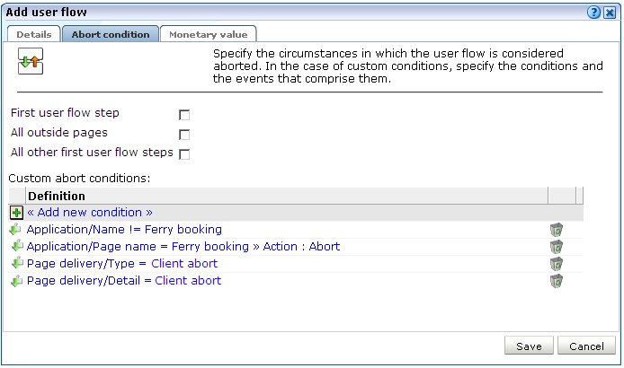
The following check boxes are available:
First user flow step: specifies whether the user flow is regarded as aborted if the visitor returns to the first step. The default is unchecked.
All outside pages: specifies whether the user flow is regarded as aborted if the visitor navigates to any page not defined as a step within the selected user flow. The default is unchecked.
All other first user flow steps: specifies whether the user flow is regarded as aborted if the visitor navigates to any page which is defined as the first step of another user flow. The default is unchecked.
Optionally, click the « Add new condition » item to specify the specific pages (or other dimensions) to which if the visitor navigates the user flow is regarded as aborted.
Optionally, click the Monetary value tab, and use the Monetary source menu and the Source value fields shown in Figure 6-51 to specify the source upon which the user flow's reported monetary value should be based. The use of this facility is fully described in Section 6.6.4, "Assigning Monetary values to User Flows".
The monetary value can be derived from a URL argument, an XPath expression, a header, a cookie, or a custom tag or function. More information about using XPath queries is available in Appendix F, "Working with XPath Queries".
When ready, click Save. Monitoring of the new user flow starts within five minutes. An overview of the new user flow appears.
Understanding how Event Steps are Handled
When analyzing reported user flow information, it is important to understand the sequence in which RUEI attempts to processes user flow activity. This can be summarized as follows:
RUEI first attempts to determine whether a visitor has made progress through the user flow. That is, whether they have moved to the next step. If so, the reported progress is updated to reflect this.
If there is no direct progress to the next step, then each of following steps (as long as they are optional) are checked for progress. If progress is determined, this is reported.
If no progress has been determined, then the current step is checked and, if this fails, all previous steps (as long as they are optional) are checked. Any determined progress is reported.
If all checks until now have failed to identify progress through the user transaction, then the abort conditions are checked. If met, the user flow is reported as aborted. Otherwise, the user flow's current status is reported as an outside activity.
It is recommended that you pay particular attention to the following points when defining your user flows:
Because a user flow is considered completed when a visitor reaches the last step, you should always define a confirmation or completion page as the final step.
When defining optional steps, ensure that the Web site is structured in order to regulate the approved navigation.
It is recommended that careful attention be paid to step idle times when defining your user flows. Note that if the step idle time is defined as longer than the session idle time, the session idle time takes precedence, and user flows that exceed it are reported as timed out.
Be aware that it is not possible to add or remove steps within existing user flows. The data access upon which a user flow is based can also not be modified. Therefore, it is recommended that you carefully design your user flows to reflect your requirements before configuring them.
Note that it is possible to modify step conditions, as well as other user flow information (such as its name, location, abort conditions, and monetary value). To modify a user flow, do the following:
Select Configuration, then Application, and then User flows. Click the appropriate category and user flow on the left-hand side of the window. An overview of the selected user flow is displayed. An example is shown in Figure 6-52.
Click the Edit command button. A dialog similar to the one shown in appears.
Optionally, select Edit from a step's context menu to modify its name, idle time, or optional/mandatory setting. As explained earlier, a user flow must contain at least two steps, and the first and last steps are mandatory. When ready, click Save.
Optionally, you can also click individual step conditions to modify them, or click the Remove icon beside them to delete them. You can also click the Add new condition item within a step to define additional conditions for the step.
When ready, click Save. Any changes you make to a user flow definition take effect within five minutes.
Because only restricted changes can be made to existing user flows, it is very convenient to use the Copy option under the user flow context menu in the left-hand side of the window. In particular, it allows you to perform "what if" analysis of problem user flows.
For example, imagine that a particular step within a user flow has a high abort rate associated with it. You suspect that the problem may be related to visitors' browser language settings. Using the copy facility, you make a duplicate of the user flow, and modify the necessary step definition. Thereafter, you can compare the results of the original and modified user flows to see whether user flow conversions have improved.
Each time a new user transaction is created, the steps within that transaction are assigned an idle time. That is, the period of visitor inactivity after which the step is regarded as timed out. This has a default of 10 minutes. However, this default can be modified by selecting Configuration, then General, then Advanced settings, then Session processing, and then Default user flow step time. Note that any change to this setting only applies to new user transaction definitions. Existing user flows are unaffected.
In order to provide insight into the real cost of performance issues, monetary values can be assigned to ended user flows. That is, user flows that are completed, timed out, or aborted. For example, using this facility, you could determine the cost of a server upgrade in terms of lost user flows. The source of the monetary value is specified in a similar way to custom dimensions (see Section 3.9, "Working With Custom Dimensions"). An example of a comparison between the monetary values of different user flows is shown in Figure 6-53.
Figure 6-53 Example Overview of User Flow Monetary Totals
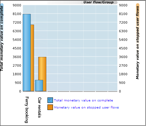
When assigning monetary values to user flows, you should consider the following:
When determining the monetary value form a selected element, all leading whitespace is removed from it. The value is taken from the first numeric character encountered up to the next non-numeric character. For example, the element "?Basket=99.99 US dollars" would be calculated as 99.
If the value is determined to be negative, greater than 232, or a string, zero is returned.
The underlying element (such as a request header) can change over the course of the user flow. Consider the situation shown in Figure 6-54. When user flow A starts, it has a monetary value of 0. As the user flow progresses, it has values of 80, 120, and 90. Upon completion, the monetary value of 90 is reported for it.
Figure 6-54 Calculation of Reported Monetary Value

The funnel view provides the most generic information about a selected user flow. It indicates visitor transition through the user flow during the selected time period. An example is shown in Figure 6-55.
More detailed information about the current status of a selected user flow is available through the Flow status view. In particular, it highlights the number of visitors currently engaged within each step, how they experienced Web actions (such as page loading and errors) within those steps, as well as the number of timed out and aborted steps. An example is shown in Figure 6-56.
Figure 6-56 Example User Flow Status details
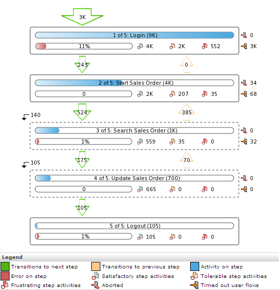
Optional steps within a user flow are indicated with dotted lines. Note that diagnostics information with full session information about specific errors experienced on steps is available by clicking the Error on step indicator within a step. The use of this facility is fully explained in Section 3.10, "Working With the Diagnostics Facility".
The most detailed information about a user flow is available via the Flow transitions view. An example is shown in Figure 6-57.
Figure 6-57 Example User Flow Transition Details
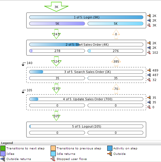
It provides extensive information about transitions between steps, including the level of outside activity within steps, aborts, time outs, and the skipping of optional steps. Note that the Idle item indicates the number of visitors engaged in a step but who have been inactive for longer than the defined step idle time. If these visitors resume activity within one hour, this is indicated via the Idle returns item. Otherwise, the step is considered timed out and stopped.
Within the Service test diagnostics group (described in Section 3.2.6, "Oracle Enterprise Manager Service Test Monitoring"), you can convert selected service test sessions into RUEI user flows. This offers the advantage that the monitored user flows would then be reported within the Transactions group. This not only allows immediate comparison with other monitored user transactions, but also enhanced reporting facilities.
To convert a service test session into a RUEI user transaction, you must have Full Business access level permission. Do the following:
Select Browse data, the Service test group, and click the Service test diagnostics facility. A diagnostics panel similar to the one shown in Figure 3-23 appears. For a general explanation of the diagnostics facility, see Section 3.10, "Working With the Diagnostics Facility".
Use the Calendar controls (described in Section 2.4, "Using the Calendar") to select the required period. The selected viewing range must be a single day (or less). If you attempt to search outside this limit, an error is reported. When ready, click Search. The results of the search are shown in the main part of the window. An example is shown in Figure 6-58.
To use the search facility, specify a search pattern, and click Go. Note that, unlike other diagnostics groups, the specified search pattern must refer to the beacon name or service test name.
After selecting a service test session, click the Create user flow command button in the Service test diagnostics toolbar to convert the selected service test session to a RUEI user transaction. The dialog shown in Figure 6-59 appears.
Figure 6-59 Add User Flow From Service Test Session Dialog
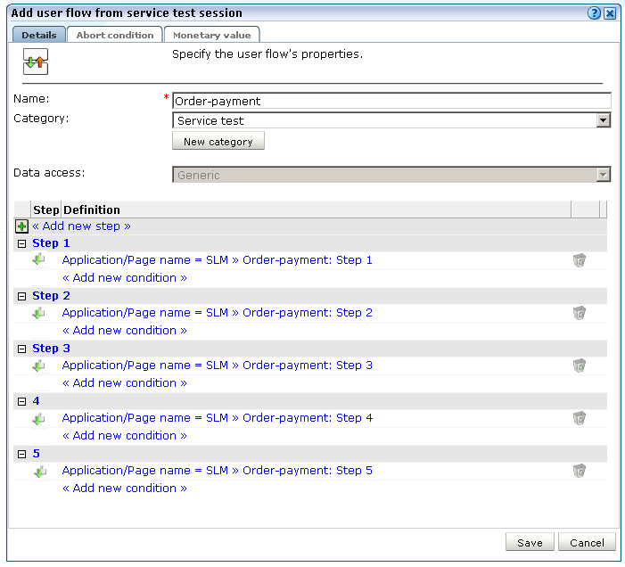
Specify a name for the new user flow. This must be unique within the selected user flow category. The default is the monitored service test name.
Specify the category within which the new user flow should be saved. This can either a be an existing category or a new one. The default is "Service test".
Optionally, use the context menu available under each step name to edit its details, delete it, or change its position within the new user flow.
When ready, click Save.
When converting service test sessions into user flows, be aware of the following:
The new user flow is limited to a maximum of 15 steps, and any service test session containing steps over is this limit are automatically truncated.
Each step must have a unique name within the created user flow.
The converted user flow must have at least two steps.
It is not possible to create user flows from service test sessions that contain multiple transactions or duplicate steps.