5 Configuring Exalogic Networking for a Physical Environment
This chapter describes Physical Exalogic Networking.
The contents in this chapter are specific to the Exalogic physical environment and should be read in conjunction with the Chapter 4, "Networking Overview."
This chapter contains the following sections:
5.1 Network Map
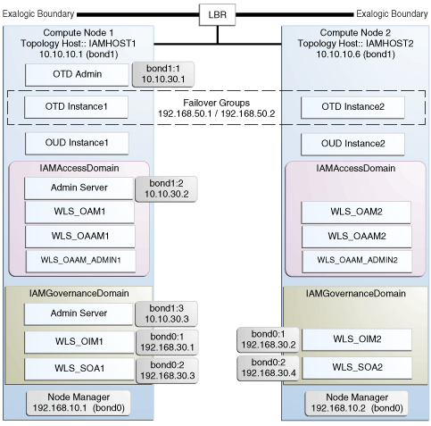
The following image illustrates the IPoIB and EoIB network interfaces needed for an Oracle Identity Management enterprise deployment. The sections that follow provide a detailed description of the image.
5.2 Explanation of the Network Interfaces Map
In a physical Exalogic deployment, A hardware load balancer distributes requests to two compute nodes in the Exalogic Rack. All of the Identity Management and Oracle Traffic Director software is deployed across these two compute nodes in a highly available fashion. Figure 5-1 shows how these compute nodes are networked together and to the external corporate network where the load balancer sits
This section contains the following topics:
5.2.1 Load Balancer
An external load balancer sits outside of the exalogic machine rack. Its purpose is to receive requests on the public ethernet network and distribute those requests to the Oracle Traffic Director nodes inside the machine rack using the front end EoIB network or to the external Oracle HTTP Servers.
5.2.2 Network Interface Bonding
In order to maintain maximum availability, individual network interfaces are bonded together so that the failure of one interface will not affect the availability of the system.
In Physical Exalogic Deployments the following network bonding is assumed:
| Network Interface | Purpose |
|---|---|
| bond0 | This is the internal network used for communication between applications and with Exadata (if used). |
| bond1 | This is the external client access network |
These are the default network interfaces all of which have an associated IP address. Virtual IP addresses can temporarily be added to these network interfaces as required by the IAM deployment. Virtual IP addresses are shown as :x where x is a sequential number. For example bond1:1.
5.2.3 Oracle Traffic Director
Oracle Traffic Director (OTD) serves two functions: load balancing, and HTTP server.
As a load balancer, Oracle Traffic Director is configured in a way that it can direct requests to the Oracle Unified Directory servers using the internal IPoIB network using TCP and to direct internal call back requests from Oracle Traffic Director to SOA servers using the internal IPoIB network using HTTP.
Unless External Oracle HTTP Servers are used, then Oracle Traffic Director also functions as an HTTP Server. Oracle Traffic Director listens on the front end EoIB network for HTTP requests originating from the external load balancers. If these requests require access to the WebLogic managed servers on the compute nodes, then it directs these requests accordingly using the internal IPoIB network.
5.2.4 External Oracle HTTP Servers
Optionally, you can use Oracle HTTP Servers, which sit on servers outside of the Exalogic machine rack. These servers receive requests from the load balancer and distribute those requests to application compute nodes inside the machine rack using EoIB. All internal traffic still takes place using IPoIB and Oracle Traffic Director.
External HTTP Servers may be required in organizations that need to place the Web Tier in a separate DMZ than the Exalogic machine. Or have other applications or policies that require an HTTP Server.
5.2.5 Compute Nodes
In an Exalogic Physical deployment, the physical compute nodes are used to host services.
The following sections describe the networking configuration of each of the Compute Nodes in the deployment.
5.2.5.1 ComputeNode1
ComputeNode1 serves two purposes. It hosts Oracle Traffic director, which acts as both an internal load balancer and a web server. It also hosts the Oracle Identity and Access Management Applications which comprise Access Manager, Oracle Identity Manager and Oracle Unified Directory.
-
It is configured to use the EoIB client access network. It uses this network to communicate with the external load balancer.
-
It is configured to use the IPoIB network for internal communications.
-
Oracle Traffic Director enables an IP address using a failover group to route requests to the Oracle Unified Directory servers using the IPoIB network.
-
Oracle Traffic Director acts as a failover node in the event that the IP address used for internal callbacks fails.
-
Oracle Traffic Directory is used to route application requests to the Weblogic managed servers making up the Application Tier.
-
Node Manager, which is used to start and stop the WebLogic managed servers is configured to accept requests on the internal IPoIB interface.
-
This node hosts virtual (floating) IP addresses which are configured on the client access network. These virtual IP addresses are used by the administration servers. Although not necessary to use the client access network. The benefit of doing so is that it is possible to monitor the administration servers outside of the Exalogic machine.
-
Two virtual (floating) IP addresses are attached to the IPoIB interface, which are used by the Oracle Identity Manager and SOA managed servers to facilitate server migration.
-
Oracle Unified Directory listens for requests on the internal IPoIB network.
5.2.5.2 ComputeNode2
ComputeNode2 serves 2 purposes. It hosts Oracle Traffic director, which acts as both an internal load balancer and a web server. It also hosts the Oracle Identity and Access Management Applications, which comprise Access Manager, Oracle Identity Manager and Oracle Unified Directory.
-
It is configured to use the EoIB client access network. It uses this network to communicate with the external load balancer.
-
It is configured to use the IPoIB network for internal communications.
-
Oracle Traffic Director enables an IP address using a failover group to route internal callback requests to SOA servers using the IPoIB network.
-
Oracle Traffic Director acts as a failover node in the event that the IP address used for Oracle Unified Directory fails.
-
Oracle Traffic Directory is used to route application requests to the WebLogic managed servers making up the Application Tier.
-
Node Manager, which is used to start and stop the local WebLogic managed servers is configured to accept requests on the internal IPoIB interface.
-
This node hosts virtual (floating) IP addresses which are configured on the client access network. These virtual IP addresses are used by the administration servers. Although not necessary to use the client access network. The benefit of doing so is that it is possible to monitor the administration servers outside of the Exalogic machine.
-
Two virtual (floating) IP addresses are attached to the IPoIB interface, which are used by the Oracle Identity Manager and SOA managed servers to facilitate server migration.
-
Oracle Unified Directory listens for requests on the internal IPoIB network.
5.3 Host Name and Networking Overview
Networking is a complicated but critical part of any Exalogic deployment. This guide utilizes the IPoIB network for internal communications and the EoIB network for external communications.
Table 5-1, "Exalogic Physical IP Addresses Worksheet" is a summary of the required networking setup in the Exalogic physical machine rack. The following sections describe in detail how to set up this networking.
A column has been added to the table to allow you to add your own values for easier cross referencing.
Appropriate host name resolution is critical to topology designs that can sustain network changes, system relocation and disaster recovery scenarios. It is important that the required DNS (either /etc/hosts or central DNS server) definitions are in place and that WebLogic Servers use host names and virtual host names instead of using IP addresses and virtual IP addresses directly. Additionally, the Exalogic enterprise deployment requires a set of virtual server names for routing requests to the proper server or service within the topology through the external load balancer and the Oracle Traffic Director servers. See Section 4.3, "Virtual Server Names Used by the Topology."
These virtual server names must be resolvable in the corporate network. IPoIB addresses must be resolved only inside the rack's name resolution system. If multiple racks are going to be connected, to elude possible IP conflict, it is good practice to place these also in a central DNS server. Network administrators at the corporate level should enable this. Alternatively host names may be resolved through appropriate /etc/hosts file propagated through the different nodes. Table 5-1, "Exalogic Physical IP Addresses Worksheet" provides an example of names for the different floating IP addresses used by servers in the SOA system.
Table 5-1 Exalogic Physical IP Addresses Worksheet
| Hostname Example for This Guide | Interface | IP Address/Subnet | Customer Value | Type | Host | Bound By | Details |
|---|---|---|---|---|---|---|---|
|
IAMHOST1 |
bond0 |
192.168.10.1/255.255.224.0 |
IPoIB/ Fixed |
ComputNode1/IAMHOST1 |
NA |
Access to IAMHOST1 using the internal IPoIB network. |
|
|
IAMHOST2 |
bond0 |
192.168.10.2/255.255.224.0 |
IPoIB/ Fixed |
ComputNode2/IAMHOST2 |
NA |
Access to IAMHOST2 using the internal IPoIB network. |
|
|
OTDADMINVHN |
bond1:1 |
10.10.30.1/255.255.224.0 |
EoIB /Floating |
ComputNode1/IAMHOST1 |
OTD Administration Server |
A floating IP address for the Administration Server is recommended, if you want to manually migrate the OTD Administration Server from IAMHOST1 to IAMHOST2. |
|
|
IADADMINVHN |
bond1:2 |
10.10.30.2/255.255.224.0 |
EoIB /Floating |
ComputNode2/IAMHOST1 |
IAMAccessDomain Administration Server |
A floating IP address for the IAMAccessDomain Administration Server is recommended, if you want to manually migrate the Administration Server from IAMHOST1 to IAMHOST2. |
|
|
IGDADMINVHN |
bond1:3 |
10.10.30.3/255.255.224.0 |
EoIB /Floating |
ComputNode1/IAMHOST1 |
IAMGovernanceDomain Administration Server |
A floating IP address for the IAMGovernanceDomain Administration Server is recommended, if you want to manually migrate the Administration Server from IAMHOST1 to IAMHOST2. |
|
|
WEBHOST1VHN |
OTD |
10.10.50.1/255.255.224.0 |
EoIB /Floating |
ComputNode1/IAMHOST1 |
OTD - IAMHOST1 |
A floating IP Address managed by OTD. This is the IP Address to which load balancers will connect. |
|
|
WEBHOST2VHN |
OTD |
10.10.50.2/255.255.224.0 |
EoIB /Floating |
ComputNode2/IAMHOST2 |
OTD - IAMHOST2 |
A floating IP Address managed by OTD. This is the IP Address to which load balancers will connect. This is optional |
|
|
OIMHOST1VHN |
bond0:1 |
192.168.30.1/255.255.240.0 |
IPoIB/ Floating |
ComputNode1/IAMHOST1 |
WLS_OIM1 Default Channel |
Initially enabled in IAMHOST1 can be failed over by server migration to IAMHOST2. |
|
|
OIMHOST2VHN |
bond0:1 |
192.168.30.2/255.255.240.0 |
|
IPoIB/ Floating |
ComputNode2/IAMHOST2 |
WLS_OIM2 Default Channel |
Initially enabled in IAMHOST2 can be failed over by server migration to IAMHOST1. |
|
SOAHOST1VHN |
bond0:2 |
192.168.30.3/255.255.240.0 |
IPoIB/ Floating |
ComputNode1/IAMHOST1 |
WLS_SOA1 default channel |
Initially enabled in IAMHOST1 can be failed over by server migration to IAMHOST2. |
|
|
SOAHOST2VHN |
bond0:2 |
192.168.30.4/255.255.240.0 |
IPoIB/ Floating |
ComputNode2/IAMHOST2 |
WLS_SOA2 default channel |
Initially enabled in ComputeNode3 can be failed over by server migration to IAMHOST1. |
|
|
IAMHOST1EXT |
bond1 |
10.10.10.1/255.255.240.0 |
EoIB/Fixed |
ComputNode1/IAMHOST1 |
NA |
A fixed IP allowing the compute node to be accessed by an External Load balancer |
|
|
IAMHOST2EXT |
bond1 |
10.10.10.2/255.255.240.0 |
EoIB/Fixed |
ComputNode2/IAMHOST2 |
NA |
A fixed IP allowing the compute node to be accessed by an External Load balancer |
|
|
IDMINTERNAL |
OTD |
192.168.50.1/255.255.224.0 |
IPoIB/ Floating |
ComputNode1/IAMHOST1 |
NA |
Oracle Traffic Director failover group for SOA |
|
|
IDSTORE |
OTD |
192.168.50.2/255.255.224.0 |
IPoIB/ Floating |
ComputNode2/IAMHOST2 |
NA |
Oracle Traffic Director failover group for Oracle Unified Directory |
Note:
In Table 5-1, where the interface is shown as OTD, means that the IP address is managed by Oracle Traffic Director rather than assigned to a network interface manually. The entries are included in this table for completeness.5.4 Additional Requirements for External OHS
If External OHS Servers are being used then the additional host names in the following table apply to an Exalogic Physical configuration.
Table 5-2 Exalogic Physical OHS Configuration Worksheet
| Hostname Example for This Guide | Interface | IP Address/Subnet | Customer Value | Type | Host | Bound By | Details |
|---|---|---|---|---|---|---|---|
|
OHSHOST1 |
eth0 |
201.19.23.10/255.255.255.0 |
ETH0/Fixed |
External OHSHOST1 |
Oracle HTTP Server |
Fixed IP that Oracle HTTP Server Listens on |
|
|
OHSHOST2 |
eth0 |
201.19.23.11/255.255.255.0 |
ETH0/Fixed |
External OHSHOST2 |
Oracle HTTP Server |
Fixed IP that Oracle HTTP Server Listens on |
|
|
OIMHOST1VHN-EXT |
bond1:2 |
10.10.10.7/255.255.224.0 |
EoIB/Floating |
ComputeNode1/IAMHOST1 |
WLS_OIM1 Default External Channel |
Initially enabled on Compute Node 1, can be failed over to Compute Node 2 |
|
|
OIMHOST2VHN-EXT |
bond1:2 |
10.10.10.8/255.255.224.0 |
EoIB/Floating |
ComputeNode2/IAMHOST2 |
WLS_OIM2 Default External Channel |
Initially enabled on Compute Node 2, can be failed over to Compute Node 1 |
Note:
OIMHOSTxVHN-EXT is used in the external Oracle HTTP Server topology instead of the standard OIMHOSTxVHN entries used in the standard topologies. The -EXT is used to show that in an Oracle HTTP Server topology the OIMHOSTxVHN is bound to the client access network, rather than the internal network as used in the other topologies.5.5 Preparing the Network on Physical Exalogic
By default, compute nodes are not able to communicate outside of the Exalogic machine rack. In order to do this you must configure the EoIB network for those hosts that are accessed via external hosts or load balancers.
The Oracle IAM hosts that require this access are IAMHOST1 and IAMHOST2, which interact with an external load balancer, external database, or Oracle HTTP Server access.
This section contains the following topics:
-
Section 5.5.1, "Summary of the IP Addresses for the EoIB Network Interfaces"
-
Section 5.5.5, "Step 4 - Configure Compute Node Networking and Assign Physical IP Address"
5.5.1 Summary of the IP Addresses for the EoIB Network Interfaces
Table 5-3, "IP Addresses for the EoIB Network and Associated Interfaces" lists the IP addresses you must associate with each EoIB interface on each compute node. Each of these interfaces is shown in Figure 5-1, "Physical Exalogic Network Map".
Table 5-3 IP Addresses for the EoIB Network and Associated Interfaces
| Compute Node | Host Name | Interface Name | External IP Address | Netmask | Used by |
|---|---|---|---|---|---|
|
ComputeNode1 |
IAMHOST1EXT |
bond1 |
10.10.10.1 |
255.255.224.0 |
Compute node for external load balancer access |
|
ComputeNode2 |
IAMHOST2EXT |
bond1 |
10.10.10.2 |
255.255.224.0 |
Compute Node for external load balancer access |
Configuring the EoIB network is a multi-stage process:
-
Stage 1 - Determine the information required to create the network devices.
-
Stage 2 - Create a Virtual LAN (VLAN) on the InfiniBand gateway switches for the compute nodes to communicate.
-
Stage 3 - Create Virtual Network Cards on the InfiniBand gateway switches which can be seen by the compute nodes, allowing the compute nodes to utilize the EoIB network.
-
Stage 4 - Configure the compute nodes to communicate using the VNICS by assigning IP addresses to them.
5.5.2 Step 1 - Gather Information
The following section describes how to gather the information required to create the VLAN and VNICs. To make things easier, complete the following worksheet as you are progressing:
| Compute Node | Administrative /External IP Address | Base Lid | GUID | Switch Lid | Switch Name | Connector | Switch GUID | MAC Address |
|---|---|---|---|---|---|---|---|---|
|
IAMHOST1 |
||||||||
|
IAMHOST2 |
||||||||
Each compute node is connected to gateway switches, the switches that the compute nodes use must have a VLAN created on them.
Note:
Administrative IP is the IP Address of the compute node as configured on the management LAN at the time of commissioning.The External IP address is the static IP address that you assign to the EoIB interface.
To determine which switches are connected to the compute nodes:
-
Login to the compute node you wish to expose using the root user.
For example:
ssh root@IAMHOST1
-
Retrieve information about the active links on the InfiniBand framework using the following command:
iblinkinfo.pl -R | grep hostnameFor example:
# iblinkinfo.pl -R | grep IAMHOST1

65   15[  ] ==( 4X 10.0 Gbps Active/  LinkUp)==>    121 2[  ] "el01cn01 EL-C 192.168.10.3 HCA-1" (Could be 5.0 Gbps)
64   15[  ] ==( 4X 10.0 Gbps Active/  LinkUp)==>    120 1[  ] "el01cn01 EL-C 192.168.10.3 HCA-1" (Could be 5.0 Gbps)
The first column shows the lid id of each of the gateway switches used. In this example, these are lids
65and64. The number after the==>symbol shows the Infiniband Port Base Lid: Make a note of these in Table 5-4, "VNIC Worksheet". -
Using the
ibswitchescommand, determine the names of the gateway switches to which the compute node is connected.#ibswitches Switch : 0x002128548042c0a0 ports 36 "SUN IB QDR GW switch el01gw03" enhanced port 0 lid 63 lmc 0 Switch : 0x002128547f22c0a0 ports 36 "SUN IB QDR GW switch el01gw02" enhanced port 0 lid 6 lmc 0 Switch : 0x00212856d0a2c0a0 ports 36 "SUN IB QDR GW switch el01gw04" enhanced port 0 lid 65 lmc 0 Switch : 0x00212856d162c0a0 ports 36 "SUN IB QDR GW switch el01gw05" enhanced port 0 lid 64 lmc 0
The example output shows that:
-
lid 64is associated with gateway switchel01gw05. -
lid 65is associated with gateway switchel01gw04.
The GUID of the switch is the last 16 characters value after the
:. For example, the GUID of Switchel101gw04is00212856d0a2c0a0.These are the gateway switches that must have a VLAN and VNICs defined. Make a note of these values in the Table 5-4, "VNIC Worksheet".
-
-
Retrieve information about the InfiniBand configuration using the
ibstatcommand.# ibstat CA 'mlx4_0' CA type: MT26428 Number of ports: 2 Firmware version: 2.7.8100 Hardware version: b0 Node GUID: 0x0021280001a0a364 System image GUID: 0x0021280001a0a367 Port 1: State: Active Physical state: LinkUp Rate: 40 Base lid: 120 LMC: 0 SM lid: 6 Capability mask: 0x02510868 Port GUID: 0x0021280001a0a365 Link layer: IB Port 2: State: Active Physical state: LinkUp Rate: 40 Base lid: 121 LMC: 0 SM lid: 6 Capability mask: 0x02510868 Port GUID: 0x0021280001a0a366 Link layer: IBThe output shows that the compute node is connected to 2 InfiniBand switches, one for each port. The Base Lid links to the value you obtained in Step 2 above.
The
ibstatcommand above shows that this compute node has two ports. Each of these ports is associated with a different switch.Use the base lid to determine the switch to which each port is connected, by comparing the base lid with the output of the
iblinkinfocommand in Step 2. In our example, port 1 has a base lid of 120, which is associated with the switch with a lid of 64. You can now determine the actual switch name by looking at the output of the commandibswitchesin step 3. In this example, this would be switchel101gw05.To summarize, on this compute node, Port Number 1, which has a GUID of
0x0021280001a0a365is connected to the switchel101gw05whose lid id is64.Make a note of the last 16 characters of each GUID in Table 5-4, "VNIC Worksheet".
You now have the information about the existing networking.
-
Determine the unique MAC address for each of the VNICs you are going to create.
The MAC address can be derived using the information in the worksheet using the following calculation:
-
The last three octets of the Switch GUID, plus the last three octets of the Internal IP address in hex. For example, the GUID of the switch
el101gw04is00212856d0a2c0a0. The last three octets are:a2c0a0. -
Separate each octet with a colon (:), for example,
a2:c0:a0. -
The internal (bond0) IP address of the Compute Node IAMHOST1 is:
192.168.10.1 -
The last three octets are:
168.10.1. Converted to Hexadecimal and separated by a colon:a8:0a:01
Therefore, you can derive the MAC address as:
a2:c0:a0:a8:0a:01Make a note of the MAC address in the worksheet.
-
-
Determine the switch upload connector.
-
Log in to one of the switches as root.
For example:
ssh root@el101gw05
-
At the command prompt, run the following:
listlinkup | grep Bridge

Bridge-0 Port 0A-ETH-1 (Bridge-0-2) up (Enabled)
Bridge-0 Port 0A-ETH-2 (Bridge-0-2) down (Enabled)
Bridge-0 Port 0A-ETH-3 (Bridge-0-1) down (Enabled)
Bridge-0 Port 0A-ETH-4 (Bridge-0-1) down (Enabled)
Bridge-1 Port 1A-ETH-1 (Bridge-1-2) down (Enabled)
Bridge-1 Port 1A-ETH-2 (Bridge-1-2) down (Enabled)
Bridge-1 Port 1A-ETH-3 (Bridge-1-1) down (Enabled)
Bridge-1 Port 1A-ETH-4 (Bridge-1-1) down (Enabled)
Identify the uplinks which can be used in the gateway. Any uplink that has a value of
upcan be used. In the example output, onlyOA-ETH-1is available for use.Using the examples above, the worksheet entries for IAMHOST1 would look as follows:
Table 5-5 Example Worksheet for IAMHOST1
Compute Node Administrative /External IP Address Base Lid GUID Switch Lid Switch Name Connector Switch GUID MAC Address IAMHOST1
10.168.10.1/10.10.10.1
120
0021280001a0a365
64
el01gw05
0A-ETH-1
00212856d162c0a0
62:C0:A0:A8:0A:01
121
0021280001a0a366
65
el01gw04
0A-ETH-1
00212856d0a2c0a0
A2:C0:A0:A8:0A:01
-
-
Log in to the InfiniBand switch where master Subnet Manager is running. For more information, refer to the Oracle Exalogic Elastic Cloud Machine Owner's Guide.
-
Run the following command to start the configuration process:
smpartition start
-
Run the following command to create a myEoIB partition with the pkey 0x005 with a full membership:
smpartition create -n myEoIB -pkey 0x005 -m full
-
Use the following command to add the compute node port GUIDs to the IB partition defined by partition key created previously. Use this partition key while creating the VLAN as described in Section 5.5.3.
smpartition add -pkey pkey -port compute_node_port_GUID -m both
Where
pkeyis the partition key of the IB partition created in this step. Use this pkey when creating the VLAN.compute_node_port_GUIDis the GUID value from the worksheet. -
Run the following command to view the changed partition configuration:
smpartition list modified
This command displays the new partition with its pkey, ports added to the partition, and membership type.
-
Run the following command to confirm the partition configuration:
smpartition commit
5.5.3 Step 2 - Create a Virtual LAN
Create a virtual LAN on each of these switches using the following steps:
-
Log in to the gateway switch that you stored in the worksheet, for example,
el01g04, as the userilom-admin.For example:
ssh ilom-admin@el01gw04
-
Change to the system management framework by entering the following:
cd /SYS/Fabric_Mgmt
For example:
Oracle(R) Integrated Lights Out Manager

Version ILOM 3.0 r47111

Copyright (c) 2010, Oracle and/or its affiliates. All rights reserved.
-> cd /SYS/Fabric_Mgmt
-
Launch a restrict shell by entering the
showcommand:show
-
Run the following command to associate a connector with the VLAN that will be used:
createvlan connector -vlan 0 -pkey default
Where:
connectoris the name of the switch interface from the worksheet.vlanis the number of the Virtual Lan.pkeyis the partition key. -
Verify the virtual LAN is working using the following command:
showvlan
Expected output:
Connector/LAG VLN PKEY ----------- ---- ---- 0A-ETH-1 125 ffff 0A-ETH-1 0 ffff -
Repeat once for each switch in the VNIC worksheet.
5.5.4 Step 3 - Create Virtual Network Cards
Create a virtual network card on the switch to allow compute nodes to recognize it as a network card it can use for communication.
You need to create a VNIC for each port on each switch attached to each externally facing compute node. Refer to Table 5-4, "VNIC Worksheet" for details.
To create a VNIC:
-
Login to the gateway switch you stored in the worksheet, for example,
el01g04as the userilom-admin.For example:
ssh ilom-admin@el01gw04
-
Change to the system management framework by entering the following:
cd /SYS/Fabric_Mgmt
For example:
Version ILOM 3.0 r47111

Copyright (c) 2010, Oracle and/or its affiliates. All rights reserved.
-> cd /SYS/Fabric_Mgmt
-
Launch a restrict shell by entering the
showcommand:show
-
Run the following command to a VNIC:
createvnic connector -guid compute_node_port_GUID -mac unique_mac_address -pkey default -vlan 0
Where
connectoris the Connector column in the worksheet.compute_node_port_GUIDis the GUID column in the worksheet.unique_mac_addressis the MAC Address in the worksheet.pkeyandvlanare the values you used when you created the VLAN in Section 5.5.3, "Step 2 - Create a Virtual LAN."For example:
createvnic 0A-ETH-1 -guid 0021280001a0a366 -mac A2:C0:A0:A8:0A:01 -pkey default -vlan 0
-
Verify that the VNIC has been created properly by running the following command:
showvnics
Example output:
ID  STATE    FLG IOA_GUID                NODE                             IID  MAC               VLN PKEY GW
--- -------- --- ----------------------- -------------------------------- ---- ----------------- --- ---- --------
94  UP       N   0021280001EFA4BF        el01cn01EL-C 192.168.10.1        0000 A2:C0:A0:A8:0A:01 0   ffff 0A-ETH-1
Look for the MAC address of the card created and verify that its status is shown as
up. -
If the VNIC is up, repeat Steps 1-5 to add a VNIC to the next interface. If the VNIC is in a WAIT state, follow Steps 7-9 to ensure the Port GUID has been added to the Pkey.
-
Log onto the master switch. This can be obtained by issuing the following command at any switch:
getmaster
-
Log back on to the switch from Step 5 and confirm the VNIC is now up:
showvnics
-
Repeat all the steps, starting with Step 1, to create each of the necessary VNCs.
5.5.5 Step 4 - Configure Compute Node Networking and Assign Physical IP Address
Define a new bonded network interface on the compute node that exposes the vNICs you just created as a single interface to applications, so that the compute node can be accessed using a fixed IP by an external load balancer. Each compute node has two Virtual Network Interface Cards created.
To make configuring the network easier you can use the following worksheet:
| Compute Node | EoIB IP Address | Netmask | Interface | Network Device | MAC Address | EPORT_ID | IOA_PORT | Interface Device Name | Interface File |
|---|---|---|---|---|---|---|---|---|---|
|
IAMHOST1 |
|||||||||
|
IAMHOST2 |
|||||||||
To configure the network:
-
Log in to the compute node as the root user.
For example:
ssh root@IAMHOST1
-
On the compute node, run the following command to display the list of VNICs available:
mlx4_vnic_info -i
This command returns the details of the virtual network cards. Make a note of the following in the worksheet:
-
Network Device -
MAC Address -
EPORT_ID -
The number following the colon (:) of the
IOA_PORT.
-
-
Create interface files for the VNICs on the compute node.
To ensure correct failover behavior, the name of the VNIC interface file and the value of the DEVICE directive in the interface file must not be based on the kernel-assigned
ethXinterface name (eth4,eth5, and so on). Instead, Oracle recommends that the interface file name and value of theDEVICEdirective in the interface file be derived from theEPORT_IDandIOA_PORTvalues:Note:
Any other unique naming scheme is also acceptable.-
Determine the interface device name using the following convention:
ethEPORT_IOA_PORTFor example:
eth331_1
Make a note of the interface device name in the worksheet.
-
Determine the interface file name using the following convention:
ifcfg-DeviceNameFor example:
ifcfg-eth331_1
Make a note of the interface file name in the worksheet.
Using the examples above for IAMHOST1, the worksheet entry would look as follows:
Compute Node EoIB IP Address Netmask Interface Network Device MAC Address EPORT_ID IOA_PORT Interface Device Name Interface File IAMHOST1
10.10.10.1
255.255.224.0
bond1
eth4
A2:C0:A0:A8:0A:03
331
1
eth331_1
ifcfg-eth331_1
eth5
62:C0:A0:A8:0A:03
331
2
eth331_2
ifcfg-eth331_2
Note:
Table 5-1 Exalogic Physical IP Addresses Worksheet, shows the interface (Bond name) for various types of communication. The interface for compute nodes to be accessed by external load balancer using a fixed IP is Bond1.The MAC address is the value of the MAC address generated in the VNICs worksheet.
-
Create the interface file for the first VNIC,
eth4in the example, by using a text editor, such as VI, and save the file in the following directory:/etc/sysconfig/network-scripts
Name the file
ifcfg-eth331_1(from the worksheet).This file will have the following contents:
DEVICE=eth331_1
BOOTPROTO=none
ONBOOT=yes
HWADDR=a2:c0:a0:a8:0A:03
MASTER=bond1
SLAVE=yes
MTU=1500
Where:
DEVICEthe Derived Name in the worksheet.HWADDRis the Mac Address in the worksheet. -
Create a second interface file for the remaining network card.
-
Create a bonded Ethernet Card encompassing each of the network devices by creating a file named
ifcfg-Interface, for example:ifcfg-bond1
The file will have the following contents:
DEVICE=bond1
IPADDR=10.10.10.1
NETMASK=255.255.224.0
BOOTPROTO=none
USERCTL=no
TYPE=Ethernet
ONBOOT=yes
IPV6INIT=no
BONDING_OPTS="mode=active-backup miimon=100 downdelay=5000 updelay=5000"
GATEWAY=10.10.18.1
MTU=1500
Where:
Deviceis the Interface Name.IPADDRis the external IP address being assigned.NETMASKis the netmask of the IP Address.GATEWAYis the IP address of your gateway. -
Restart networking using the following command:
service network restart
-
5.6 Routing for Multi-Homed Hosts
Now that you have added new interfaces to each Host, having only one default gateway might not be sufficient. You might want to have one interface for an Internet connection and another for a corporate WAN, for example.
In the example below, the different interfaces are shown, along with example IP addresses and gateway requirements:
| Interface | IP Address | Gateway Requirements |
|---|---|---|
| eth0 | 201.19.23.128 / 24 | Gateway IP 201.19.23.1 |
| bond0 | 192.168.10.1 / 24 | No Gateway requirements |
| bond1 | 10.10.10.101/ 24 | Gateway IP 10.10.10.1 |
As you can see, eth0 and bond1 must have their own respective default gateways.
Bond0, however, does not have any default gateway requirements. It is simply confined to their actual Layer 3 subnet.
To get around this, create rules and tables for routing lookups, as follows.
-
Check the existing table IDs by issuing this command:
ip rule list
-
Choose a unique id that has NOT already been used. In this example, we'll use 224 and 225.
-
For eth0, create the following two files:
The file
/etc/sysconfig/network-scripts/rule-eth0, which contains:from 201.19.23.128/32 table 224 to 201.19.23.128 table 224
The file
/etc/sysconfig/network-scripts/route-eth0, which contains:201.19.23.0/24 dev eth0 table 224 default via 201.19.23.1 dev eth0 table 224
-
For bond1 create the following two files:
The file /etc/sysconfig/network-scripts/rule-bond1, which contains:
from 10.10.10.10/32 table 225
to 10.10.10.10 table 225
The file /etc/sysconfig/network-scripts/route-bond1, which contains:
10.10.10.0/24 dev bond1 table 225
default via 10.10.10.1 dev bond1 table 225
-
Restart the network to make the configuration effective.
service network restart
The hosts are now accessible from both routers.
5.7 Enable Virtual IP Addresses
Having completed the network chapter you need to assign virtual IP addresses to the various network interfaces and hosts as described in link to Section 9.8, "Enabling Virtual IP Addresses."
5.8 Adjust MTU (maximum transmission units) Value for IPoIB Interface bond0
When the Exalogic rack is commissioned, it sets up the networking configuration for the internal IPoIB interface bond0. Changed the MTU value created to the value 6400 for improved performance.
To change the value, edit the ifcfg-bond0 file located in the following director:
/etc/sysconfig/network-scripts
Change the value of MTU to 64000. The following example is an ifcfg-bond0 file after editing the MTU value:
######## DO NOT EDIT THIS FILE ########
######## GENERATED BY EXALOGIC ########
DEVICE=bond0
IPADDR=192.168.47.67
NETMASK=255.255.240.0
BOOTPROTO=none
USERCTL=no
TYPE=Ethernet
ONBOOT=yes
IPV6INIT=no
BONDING_OPTS="mode=active-backup miimon=100 downdelay=5000 updelay=5000"
MTU=64000
Save the file and restart the networking using the command service network restart.
See Also:
For the latest recommended values see MOS note: Revised MTU Tuning Recommendations for the IPoIB Related Network Interfaces on Exalogic Physical and Virtual Environments (Doc ID 1624434.1), which is available on My Oracle Support athttps://support.oracle.com/.5.9 Enable Multicast for bond0
Even though WebLogic clusters are configured to use unicast for cluster communications, Oracle Identity Manager has an internal dependency on multicast. For that reason, you must enable multicast on the IPoIB network.
You enable multicast by creating a file called route-bond0 in the directory /etc/sysconfig/network-scripts.
This file must have the following contents:
224.0.0.0/4 dev bond0
After creating the file, restart the network by executing the command
service network restart
5.10 Verifying Network Connectivity
After having defined the Network, ensure that all of the network names are resolvable from each of the compute Nodes/vServers.
You do this by performing the following command on each compute node/vServer
ping -I interface hostname
for example
ping -I bond1 IADADMINVHN
Perform this test for each entry in Table 5-1, "Exalogic Physical IP Addresses Worksheet" and Table 6-2, "Exalogic Virtual IP Addresses Worksheet", depending on your deployment type.
ping -I bond1 IADADMINVHN
ping -I bond0 SOAHOST1VHN
ping -I bond0 SOAHOST2VHN
ping -I bond0 OIMHOST1VHN
ping -I bond0 OIMHOST2VHN
ping -I bond0 IAMHOST1
ping -I bond0 IAMHOST2
ping -I bond1 IAMHOST1EXT
ping -I bond1 IAMHOST2ext
ping -I bond1 OTDADMINVHN
ping -I bond1 DBHOST1
ping -I bond1 DBHOST2
ping -I bond1 IAMDBSCAN
In addition, test that the compute nodes allow access to the database servers by pinging the database hosts and the Gridlink scan address. For example
ping -I bond1 DBHOST1
ping -I bond1 DBHOST2
ping -I bond1 IAMDBSCAN
5.11 Verifying Multicast Connectivity
Oracle provides a simple command to test that multicast is configured and working correctly. However, this command is available only after the Oracle software has been installed.
Use the following command to verify multicast after provisioning has been completed:
set JAVA_HOME to JAVA_HOME
Change the directory to the following:
IGD_ORACLE_HOME/coherence_3.7/bin
Run the following command:
multicast-test.sh -ttl 0 -local oimhost1
Where oimhost1 is the name of the host associated with the network interface bond0.
Run the command on each of the oimhosts to perform a multicast test.
For details about the multicast-test.sh program, see "Performing a Multicast Connectivity Test" in the Oracle Coherence Administrator's Guide.