| Oracle® Argus Insight BOXI Installation Guide, Release 6.0 E18286-01 |
|
 Previous |
 Next |
This chapter explains how to install Argus Insight and configure its various components. Before you begin installation, make sure you have read the Hardware and Software Requirements topic.
Follow these installation procedures in the order in which they appear:
Install Argus Insight Components on the Web Server
Creating the Argus Insight Datamart Structure
Configuring the Argus Insight Application
Copy Configuration: Exporting and Importing Data
Run the Initial ETL
Configuring the BOXI Server
Import Repository
Configuring the Argus Insight Web Server
Configuring LDAP Settings
Windows Firewall Troubleshooting
The Argus Insight installer installs these components:
Argus Insight 6.0 application
Universes, Dashboards, Standard Reports, and Cubes
Schema Creation Tool
Before running the Argus Insight Installer, make sure you have created the Argus Insight database instance and that it is running. Also, the database should have been created by using the character set of your Argus Safety database.
Before installing Argus Insight, verify the following.
On Argus Insight Web Server, make IUSR_<MACHINE NAME> user a member of the Administrators group.
|
Note: If you are using a Windows 2008 Server, make IUSR a member of the Administrators group. |
Please verify that the following settings are configured in IIS before running the installer:
On the Argus Insight Web Server Desktop, select Start > Programs > Administrative Tools > Internet Services Manager.
The Internet Information Services window appears.
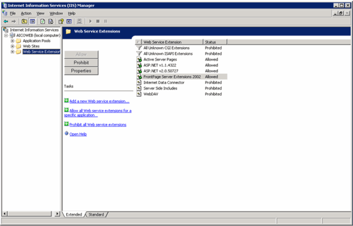
Expand the control tree item corresponding to the Web Service Extensions and configure the settings, as displayed in the right pane.
Follow these steps to run to run the Installer and install the components mentioned above.
Log on to the Argus Insight Web Server as an Admin user.
Insert the Argus Insight 6.0 CD into the CD-ROM drive of your Argus Insight Web Server or copy the Argus Insight software locally on the Insight web server.
Click Installation Wizard.
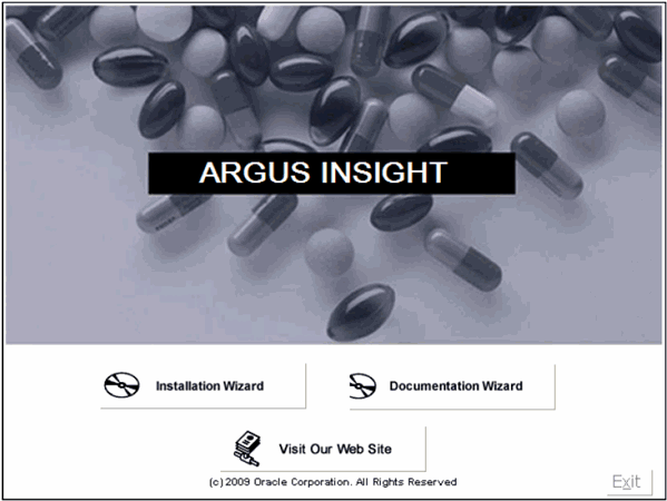
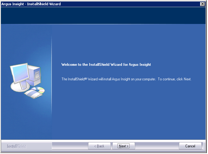
When the system opens the InstallShield Wizard, click Next.
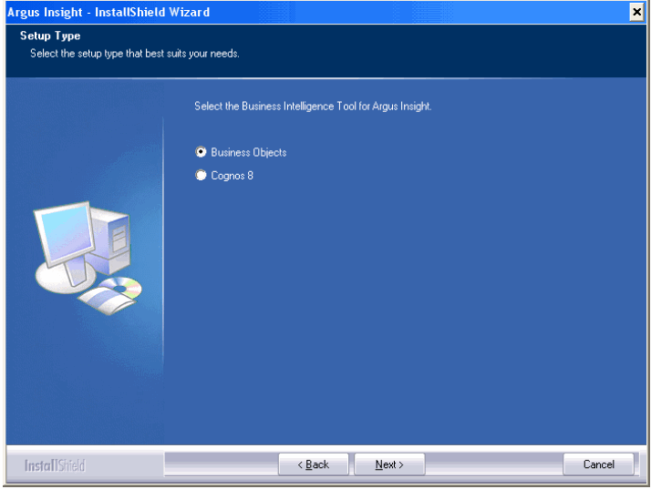
Select the Business Intelligence Tool for Argus Insight (Business Objects for BOXI Installation) and click Next.
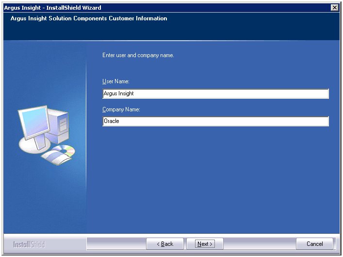
Enter User Name and Company Name. Click Next.
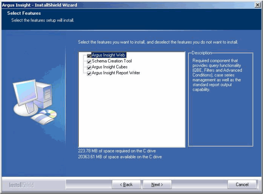
Select the required checkboxes, as per the components you want to install. Click Next.
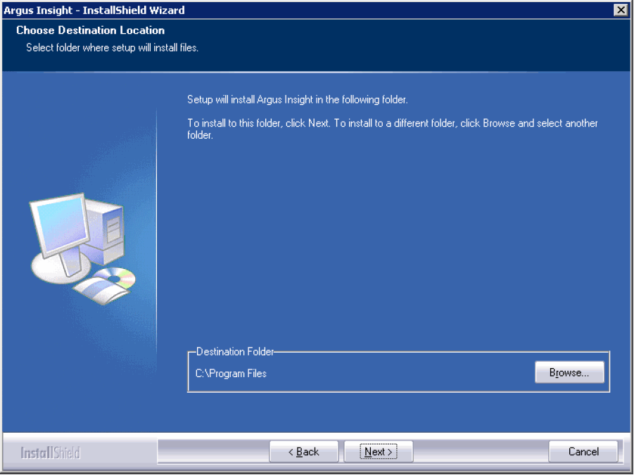
Click Next to accept the default installation location: C:\Program Files\Oracle.
Click Browse if you want to specify an alternate installation location.
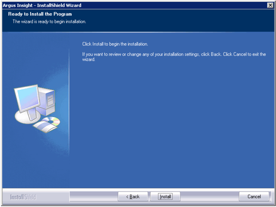
Click Install.
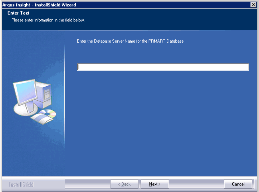
When the system opens the following window, enter the host name of the database server that has the Argus Insight datamart and click Next.
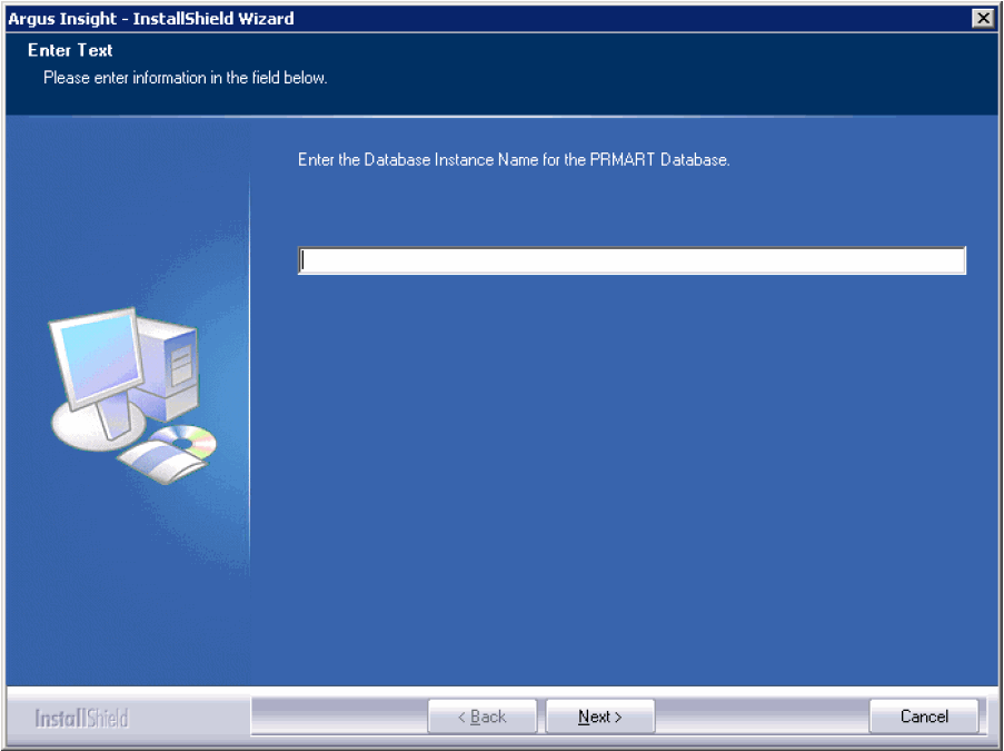
Enter the Argus Insight datamart instance name and click Next.
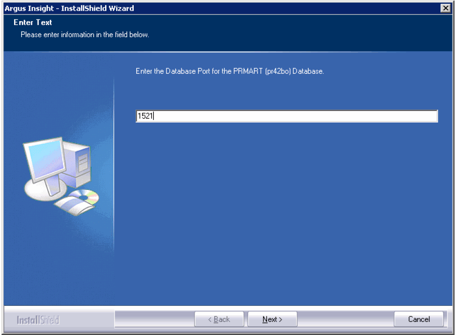
Enter the database port number you want to assign to the Argus Insight database and click Next.
The system presents the following message.

|
Note: Please wait while the Installation Wizard updates the TNSName.ORA file. |
Enter the password for APR_USER.
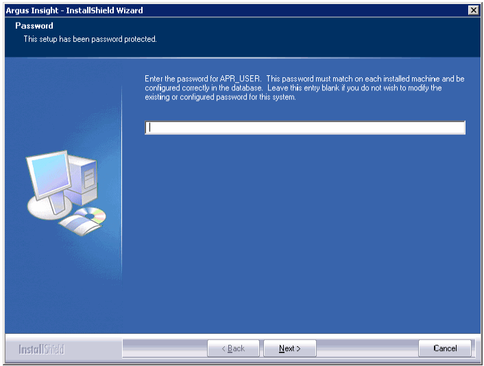
|
Note: This database user provides initial database access to application user (APR_APP) of Argus Insight. In previous versions, this user was having a hardcoded password which has been removed in this version. Please make sure that this password is same on all machines where any Argus Insight components are stored. |
You will be prompted to create/update this user during schema creation. You can modify this password by running the Argus Insight installer using modify option. For information about updating the APR_USER password see "Updating the APR_User Password" section.
When the system opens the following screen, re-enter the password for APR_USER for verification.

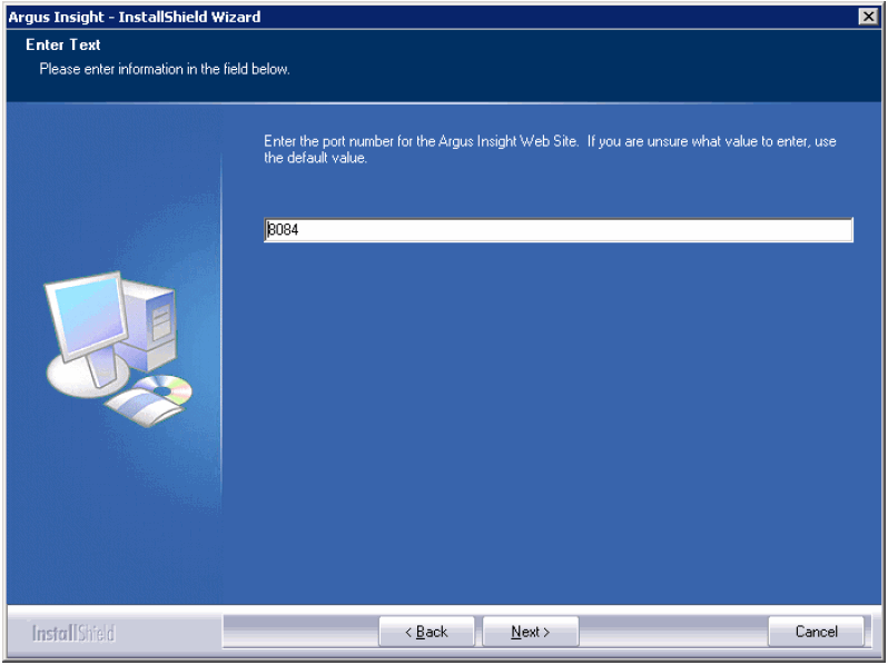
When the system opens the following window, enter the port number you want to assign to the Argus Insight Web site and click Next.
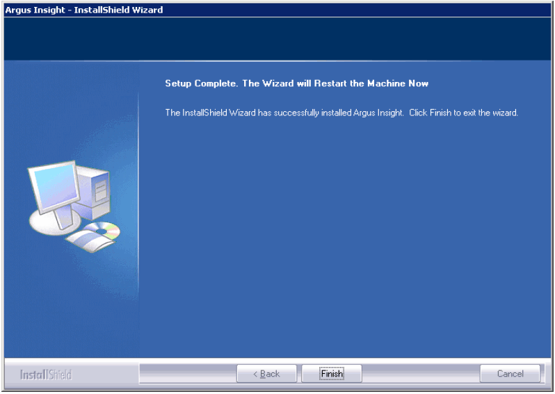
When the system presents the following window, click Finish.
When the system opens the following dialog box, click OK to restart the Argus Insight Web Server.

Please make sure to do the following before updating the password for APR_USER on any of the Insight server.
Stop the Argus Insight and Argus Perceptive Services.
Stop IIS on the Insight Web server and BOXI server.
Stop the BOXI service on BOXI server.
Update the password of APR_USER on database level.
You can modify the password for APR_USER on any Insight server by running the Argus Insight installer.
Start the Argus Insight installer.
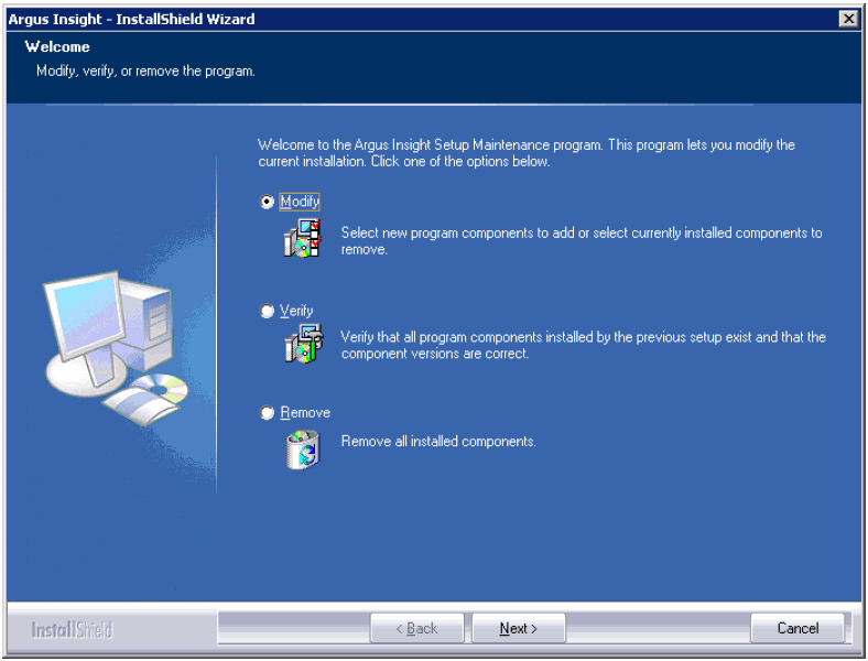
When the system opens the following dialog box, select Modify. Click Next.
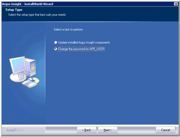
When the system opens the following dialog box, select Change the password for APR_USER. Click Next.
When the system opens the following dialog box, enter the APR_USER password. Click Next.

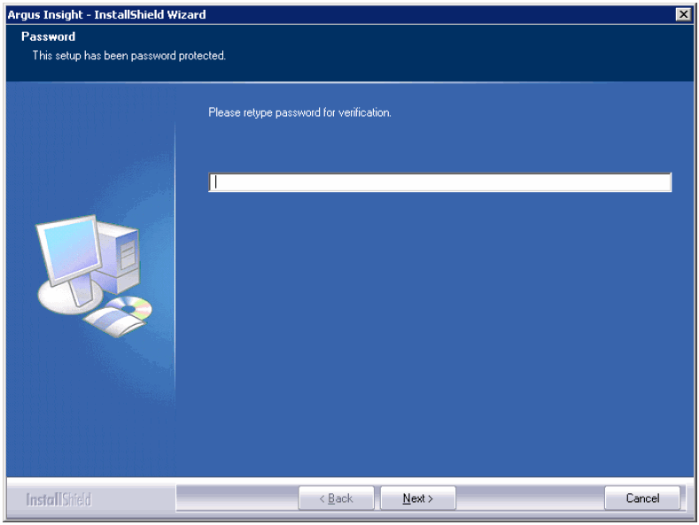
When the system opens the following dialog box, enter the APR_USER password a second time for verification. Click Next.
Password of APR_USER will be updated successfully.
The Argus Insight Schema Creation Tool lets you create the Argus Insight Datamart structure. It creates a link between your source Argus database and your new Argus Insight Datamart. The ETL process uses this link to transfer data from your Argus database to the Argus Insight Datamart for reporting purposes. During this process, you are required to create four database users: one for logging in to the Argus Insight application, two other users who are schema owners, and one for supporting Private DB Links.
|
Note: The Argus Insight database must be created with same Character Set as the Argus Safety Database. Make sure you have installed that requisite software as explained in theHardware and Software Requirementstopic. |
Before running the schema creation tool, contact your Database Administrator (DBA) to verify the following.
§Verify these database parameter values in the Database configuration file for the Argus Insight database:
global_name = false
job_queue_processes=10
Add "SET ARRAYSIZE 5000" in file glogin.sql ($ORACLE_HOME/sqlplus/admin/glogin.sql)
The following table lists the minimum values required on different Database Parameters for Argus Insight.
The Database Administrator should monitor these values to increase/decrease the parameters.
| Argus Insight Database Instance Parameters | Small (Less than 30,000 Cases) | Medium (30,000 - 200,000 Cases) | Large (200,000 - 1 Million Cases) | Very Large (More than 1 Million Cases) | Remarks |
|---|---|---|---|---|---|
| Value | Value | Value | Value | ||
| Shared_Pool_Size | Default | Default | Default | Default | |
| DB_Block_Buffers (Size in MB) / DB_Cache_Size | Default | Default | Default | Default | |
| DB_Block_Size (bytes) | Default | Default | Default | Default | |
| SGA_Target | 1 GB | 2.5 GB | 3.5 GB | 4.5 GB | The 32-bit architecture allows for 4 GB of physical memory to be addressed, DBAs are requested to verify the maximum addressable RAM for their respective architectures. |
| SGA_Max_Size | >= value for SGA_TARGET | >= value for SGA_TARGET | >= value for SGA_TARGET | >= value for SGA_TARGET | |
| PGA_AGGREGATE_TARGET | 0.5 GB | 2 GB | 3 GB | 4 GB | |
| CURSOR_SHARING | EXACT | EXACT | EXACT | EXACT | |
| OPTIMIZER_SECURE_VIEW_MERGING | TRUE | TRUE | TRUE | TRUE | |
| WORKAREA_SIZE_POLICY | AUTO | AUTO | AUTO | AUTO | |
| QUERY_REWRITE_ENABLED (If Computing Statistics regularly) | TRUE | TRUE | TRUE | TRUE | |
| QUERY_REWRITE_ENABLED (If Not Computing Statistics regularly) | FALSE | FALSE | FALSE | FALSE | |
| QUERY_REWRITE_INTEGRITY | Default | Default | Default | Default | |
| GLOBAL_NAME | False | False | False | False | |
| PARALLEL_MAX_SERVERS | 16 | 32 | Default | Default | |
| OPTIMIZER_MODE | ALL_ROWS | ALL_ROWS | ALL_ROWS | ALL_ROWS | |
| COMPATIBLE (For Oracle 10g) | 10.2.0.1 or Higher | 10.2.0.1 or Higher | 10.2.0.1 or Higher | 10.2.0.1 or Higher | |
| COMPATIBLE (For Oracle 11g) | 11.1.0.6 or Higher | 11.1.0.6 or Higher | 11.1.0.6 or Higher | 11.1.0.6 or Higher | |
| UNDO_MANAGEMENT | AUTO | AUTO | AUTO | AUTO | |
| NLS_LENGTH_SEMANTICS | CHAR | CHAR | CHAR | CHAR |
| Argus Insight Database I/O Configuration | Small | Medium | Large | Very Large | Remarks |
|---|---|---|---|---|---|
| Value | Value | Value | Value | ||
| Number and Size of Redo Log Files | Default | 3 X 500 MB | 5 X 500 MB | 5 X 500 MB | Depends on the characteristics of the I/O subsystem like the I/O bandwidth,Storage Disks type,RAID Level, etc. (Oracle recommends RAID 1+0 or similar) |
| TEMP Tablespace size | 32 GB | 32 GB | 64 GB | 128 GB | |
| Undo Tablespace size | 16 GB | 32 GB | 64 GB | 128 GB | The recommended UNDO Tablespace size is based on the projections with the following two Parameter values:
RETENTION=NOGUARANTEE UNDO_RETENTION=900 (seconds) |
| Argus Insight Database Server Configuration | Small | Medium | Large | Very Large | Remarks |
|---|---|---|---|---|---|
| Value | Value | Value | Value | ||
| RAM | 4-8 GB | 8-16 GB | 16-32 GB | 16-32 GB | |
| CPU | Equivalent to 2-4 Dual Core, 3GHz | Equivalent to 4-8 Dual Core, 3GHz | Equivalent to 16 Dual Core, 3GHz | Equivalent to 24 Dual Core, 3GHz |
|
Note: Argus Insight Database and Argus Database TNS names entry must be available in both Argus Insight Database Server and Argus Safety Database Server. Argus Safety Database TNS should also be present in the Argus Insight Web server. |
Following are the Tablespaces for Argus Insight MART.
| S.No. | Tablespace |
|---|---|
| 1 | APR_CFG_DATA_01 |
| 2 | APR_MCAS_DATA_01 |
| 3 | APR_MCAS_DATA_02 |
| 4 | APR_MCAS_INDEX_01 |
| 5 | APR_MCAS_INDEX_02 |
| 6 | APR_MCAS_LOB_01 |
| 7 | APR_MCFG_DATA_01 |
| 8 | APR_MCFG_INDEX_01 |
| 9 | APR_MCFG_LOB_01 |
| 10 | APR_MCFG_LOG_01 |
| 11 | APR_MEDM_DATA_01 |
| 12 | APR_MEDM_INDEX_01 |
| 13 | APR_MEDM_LOB_01 |
| 14 | APR_MFACT_DATA_01 |
| 15 | APR_MFACT_DATA_02 |
| 16 | APR_MFACT_INDEX_01 |
| 17 | APR_MFACT_INDEX_02 |
| 18 | APR_MRPT_DATA_01 |
| 19 | APR_MRPT_DATA_02 |
| 20 | APR_MRPT_DATA_03 |
| 21 | APR_MRPT_INDEX_01 |
| 22 | APR_MRPT_INDEX_02 |
| 23 | APR_MRPT_INDEX_03 |
| 24 | APR_MWHOC_DATA_01 |
| 25 | APR_MWHOC_INDEX_01 |
| 26 | APR_SESM_DATA_01 |
| 27 | APR_SESM_INDEX_01 |
| 28 | APR_SESM_LOB_01 |
| 29 | APR_STAGE_DATA_01 |
| 30 | APR_STAGE_DATA_02 |
| 31 | APR_STAGE_DATA_03 |
| 32 | APR_STAGE_INDEX_01 |
| 33 | APR_STAGE_INDEX_02 |
| 34 | APR_STAGE_INDEX_03 |
| 35 | APR_STAGE_LOB_01 |
| 36 | APR_SWHOC_DATA_01 |
| 37 | APR_MCAS_HIST_DATA_01 |
| 38 | APR_MCAS_HIST_DATA_02 |
| 39 | APR_MCAS_HIST_INDEX_01 |
| 40 | APR_MCAS_HIST_LOB_01 |
| 41 | APR_MCFG_HIST_INDEX_01 |
| 42 | APR_MCFG_HIST_LOB_01 |
| 43 | APR_MFACT_HIST_DATA_01 |
| 44 | APR_MFACT_HIST_DATA_02 |
| 45 | APR_MFACT_HIST_INDEX_01 |
| 46 | APR_MFACT_HIST_INDEX_02 |
| 47 | APR_MRPT_HIST_DATA_01 |
| 48 | APR_MRPT_HIST_DATA_02 |
| 49 | APR_MRPT_HIST_DATA_03 |
| 50 | APR_MRPT_HIST_INDEX_01 |
| 51 | APR_MRPT_HIST_INDEX_02 |
| 52 | APR_MRPT_HIST_INDEX_03 |
Use the following procedure to create the database schema and run the Initial ETL.
Login (RDC) to Insight Web Server after installing Argus Insight 6.0 application using build
INSTALLDIR: Default is "C:\Program Files\Oracle"
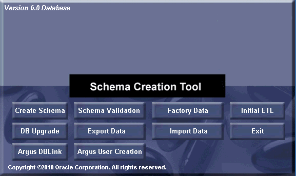
Run the schema creation tool.
Click Argus User Creation.
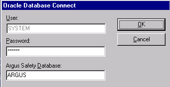
When the system opens the following dialog box, enter the Argus Safety database instance name and password for "SYSTEM". Click OK.
When the system opens the following dialog box, click New User.
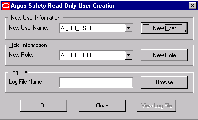
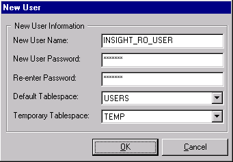
When the system opens the following dialog box, enter the name of the Argus Safety user you wish to create in the New User Name field. Click OK.
|
Note: If INSIGHT_RO_USER and INSIGHT_RO_ROLE already exists in the Argus Safety schema, you do not need to create these users again. Make the appropriate selection in step 8 below for New User Name and New Role drop downs and proceed. |
When the system redisplays the dialog box, click New Role.
When the system opens the following dialog box, enter the name of the role to create in the New Role field. Click OK.
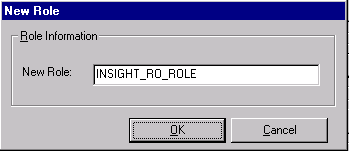
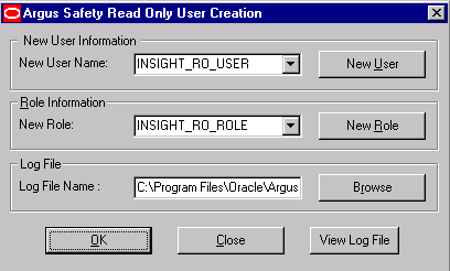
When the system opens the dialog box, select New User Name and New Role from the dropdown menu as 'INSIGHT_RO_USER' and 'INSIGHT_RO_ROLE'
When the system opens the dialog box, click Browse to select the location for the log files.
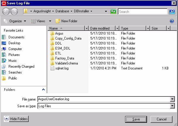
When the system opens the following dialog box, enter the name of the log file where you want to store the user creation information in the File name field.
When the system returns to the following dialog box, click OK.
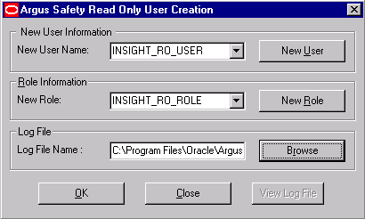
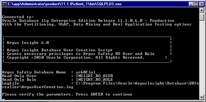
When the system opens the following screen, verify that the information on the screen is correct and press Enter.
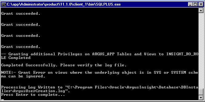
When the system displays the following screen, verify that the information is correct and press Enter to complete the installation.
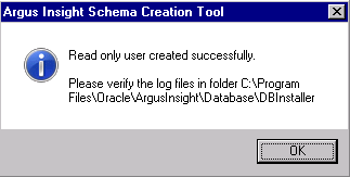
When the system displays the following message, click OK.
When the system redisplays the following dialog box, click View Log File.
When the system displays the log file, verify the log file for any errors during read only user creation.
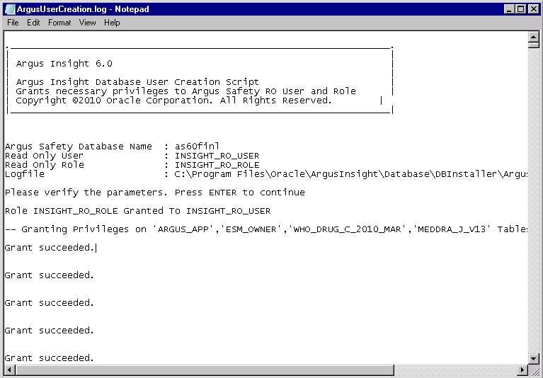
Close the log file.
Click Close button to close the 'Argus Safety Read Only User Creation' dialog.
Use the following procedures to create or upgrade the database schema, as applicable.
If you are using the same DB Installer used to create an earlier schema, you must clear its cache. Use the following procedure to clear the cache.
Press and hold the CTRL key and right-click the mouse.
When the system presents the following dialog box, click Yes.
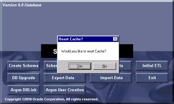
The system logs the action in the createlog.rtf file.
Use the following procedure to create a new schema for Argus Insight:
Go to Start>Programs>Oracle>Argus Insight>Schema Creation Tool.
When the system opens the following dialog box, click Create Schema.

|
Note: You must convert the Oracle parameter NLS_LENGTH_SEMENTICS to CHAR in the Argus Insight data mart. You will not be able to proceed further without changing the NLS_LENGTH_SEMENTICS to CHAR. |
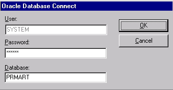
When the system opens the following dialog box:
Enter the SYSTEM user password in the Password field.
Type the TNS Entry for the Insight Database in the Database field.
Click OK.
The system displays the following message if the NLS_LENGTH_SEMANTICS parameter is not set to CHAR. You must set this parameter before you can proceed.

When the system opens the following dialog box, set the APR_MART password. Click OK.
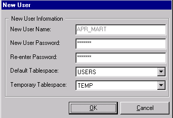
When the system opens the following dialog box, set the APR_APP password. Click OK.
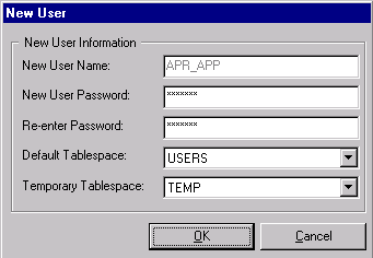
|
Note: This user will be used for all the application access and reporting. The password for this user is stored in encrypted form in CMN_PROFILE table. We cannot change password of this user as it will break down the Insight application access. If you wish to change the password for this user, please contact Oracle support for getting encrypted value of new password. |
When the system opens the Argus Insight Schema Creation Options screen, click New User to create the following users:
APR_STAGE
APR_LOGIN
APR_HIST
APR_MART_DB_LINK_USER
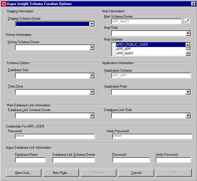
When the system redisplays the Argus Insight Schema Creation Options screen, click New Role to create the following user roles:
APR_ROLE
APR_MART_DB_LINK_ROLE
APR_APP_ROLE
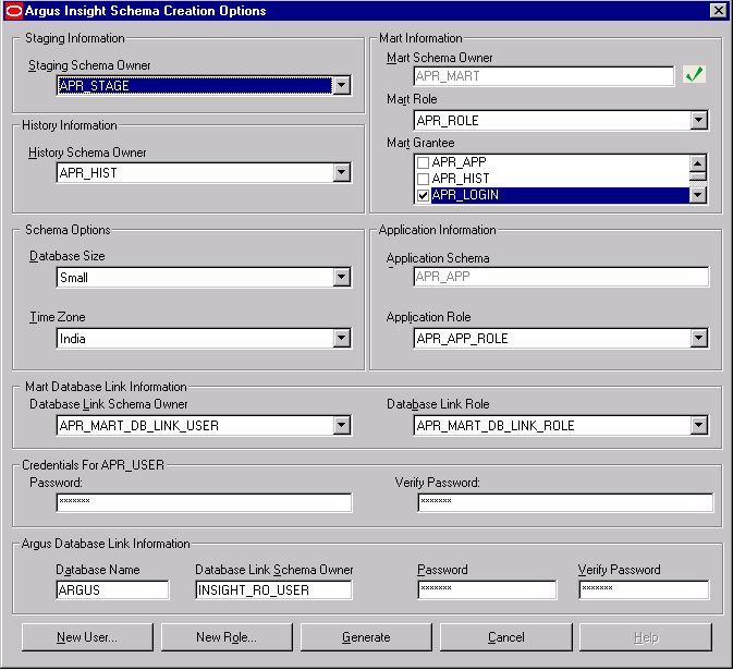
When the system opens the New Role dialog box, do the following:
Enter one of the following names in the New Role field:
A PR_ROLE
APR_MART_DB_LINK_ROLE
APR_APP_ROLE
Click OK.
The system redisplays the Argus Insight Schema Creation Options screen.
Repeat Step 9 and Steps 10 - 1 through 10 - 3 until you have created all three (3) roles.
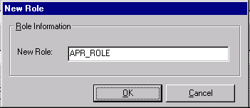
When the system redisplays the Argus Insight Schema Creation Options screen:
Select APR_MART_DB_LINK_USER in the Database Link Schema Owner field of MART Database Link Information section.
Select APR_MART_DB_LINK_ROLE in the Database Link Role field of MART Database Link Information section.
Enter INSIGHT_RO_USER in the Database Link Schema Owner field of Argus Database Link Information section.
Click Generate.
|
Note: Enter the Insight read only user name in 'Database Link Schema Owner' text box of Argus Safety link information, created using 'Argus User Creation'. Button. |

|
Note: If you want to change the password for APR_USER, edit the entries for APR_USER password textbox. |
When the system prompts for staging user's password (APR_STAGE user's password), enter the password and click OK.
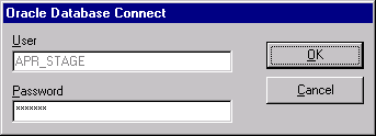
|
Note: The system displays the following message if the MART Character set is not same as the Argus character set. Please make sure the character sets for Argus Insight and Argus Safety database are the same. |

Click Yes to proceed with schema creation (not recommended) else press No.
|
Note:
|
When the system displays the following message, follow these steps
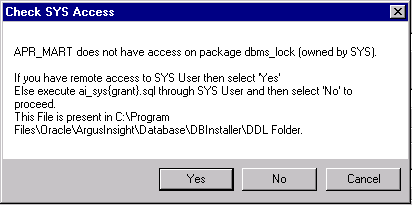
If you do not have remote access to SYS User, follow the instructions given in the message box "Check SYS Access" provided above. After executing the ai_sys{grant}.sql through SYS user, Click No and go to Step 16 of this procedure.
If you do have remote access to SYS user, click Yes and go to Step 15 of this procedure.
When the system opens the following dialog box, provide the SYS user password and click OK.
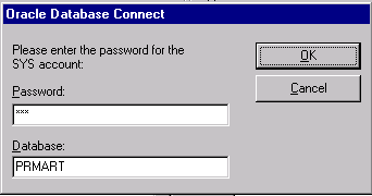
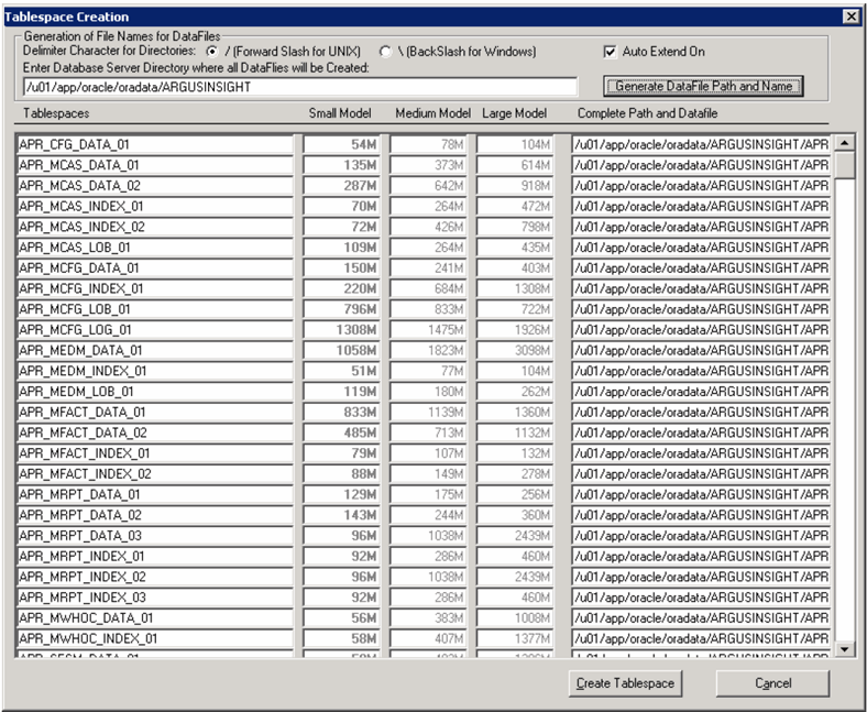
The system opens the Tablespace Creation screen as follows:
Schema Creation Tool will automatically select the Delimiter Character for the Directories radio button, based on the Database Server Operating System.
Provide the datafile path in "Enter Database Server Directory….." Textbox (For e.g. /u01/app/oracle/SMTEST, PLEASE MAKE SURE THIS DIRECTORY EXISTS) and click on button "Generate Datafile path and name".
It will fill "Complete Path and Datafile" textboxes for all table spaces.
Click Create Tablespace to create all table spaces.
Wait while the system creates the table spaces.
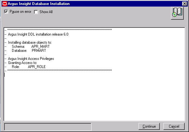
When the system opens the following window, click Continue to Start Schema Creation.
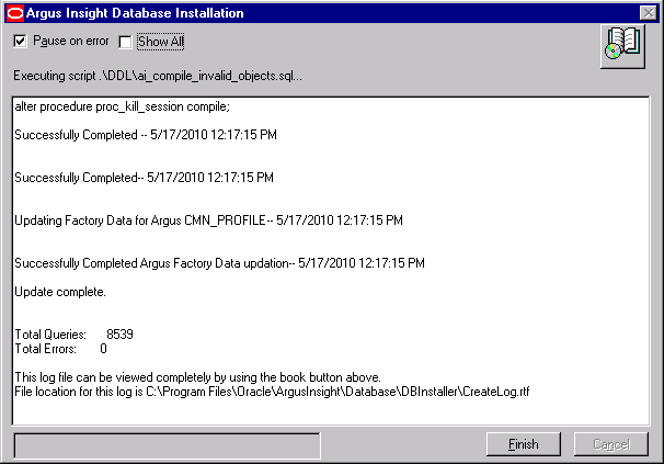
When the system displays the following window, schema creation is complete. Click Finish.
Use the following procedure to load the factory data.
Click Factory Data to load the factory data.

The system displays the following message when it finishes loading the factory data.

This section provides instructions for the upgrading from the following:
|
Note: Before upgrading a schema, ensure that you have validated the schema with the CTL file of the existing Argus Insight version. For example, before upgrading from Argus Insight 5.1 to Argus Insight 6.0, validate the schema for Argus Insight 5.1. |
Argus Insight v5.1/5.1.1 to Argus Insight v6.0
Go to Start>Programs>Oracle>Argus Insight>Schema Creation Tool.

Follow the instructions given in the section Creating Users and Roles in the Argus Safety Database for creating Argus User and Role before proceeding for the DB Upgrade.
Once Argus User and role creation is complete, click DB Upgrade.
When the system opens the following dialog box, do the following:
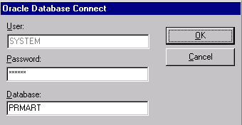
Enter the SYSTEM user password in the Password field.
Enter the TNS Entry for the Argus Insight Database in the Database field.
Click OK.
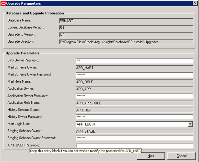
When the system opens the Upgrade Parameters window, enter the following information:
Type passwords in the following fields:
SYS Owner Password
Mart Schema Owner Password
Application Owner Password
History Owner Password
Staging Schema Owner Password
|
Note: As shown in the tool tip, enter the password for APR_USER only if you wish to modify it, otherwise leave this field blank. |
Click Next.
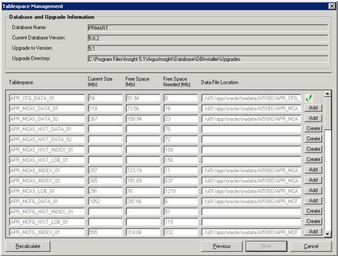
When the system opens the following window, click Add to add a new data file to an existing tablespace.
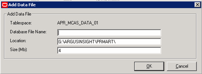
On clicking Add, the system opens the following dialog box. Enter the new data file name in the Database File Name field. Click OK.
Perform the above two steps to add all the tablespaces.
After adding and creating all the needed tablespaces and data files, click Next.
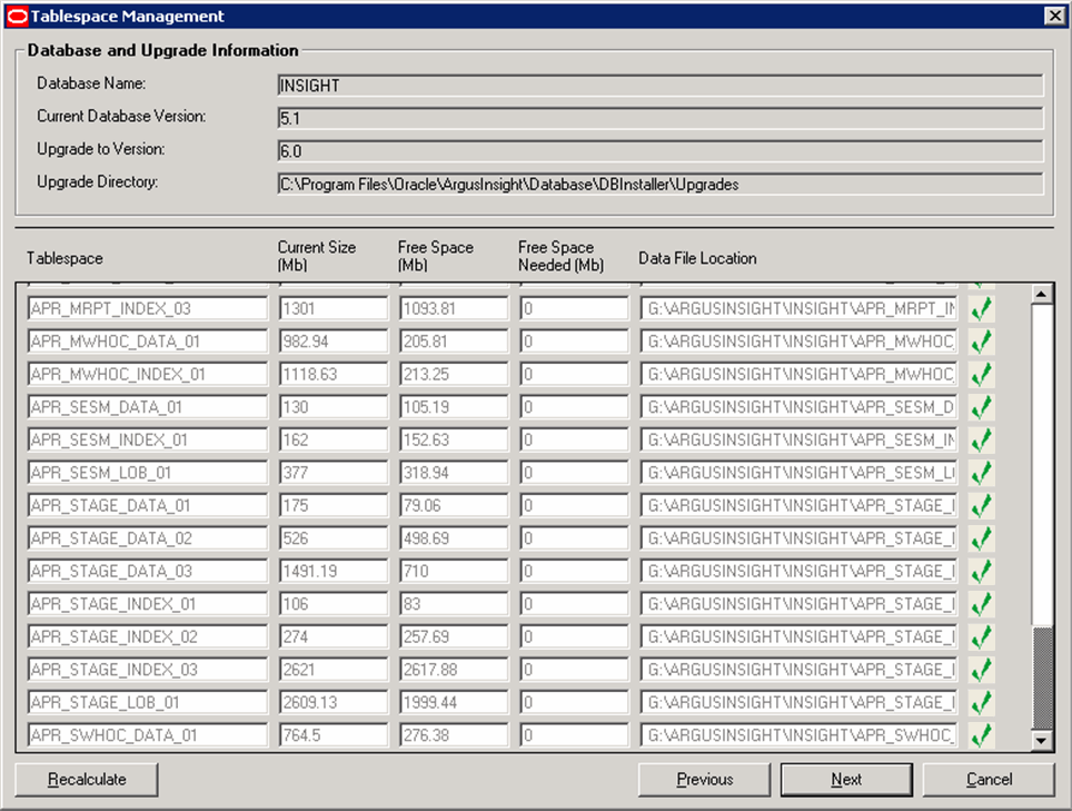
When the system opens the following window, click Continue to start the upgrade.
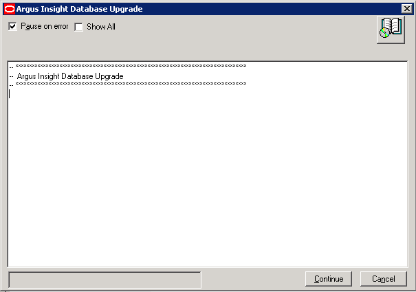
When the system completes the upgrade, the following screen is displayed. Click OK.
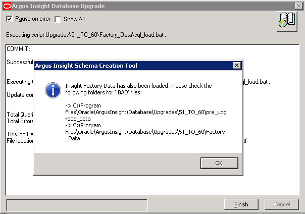
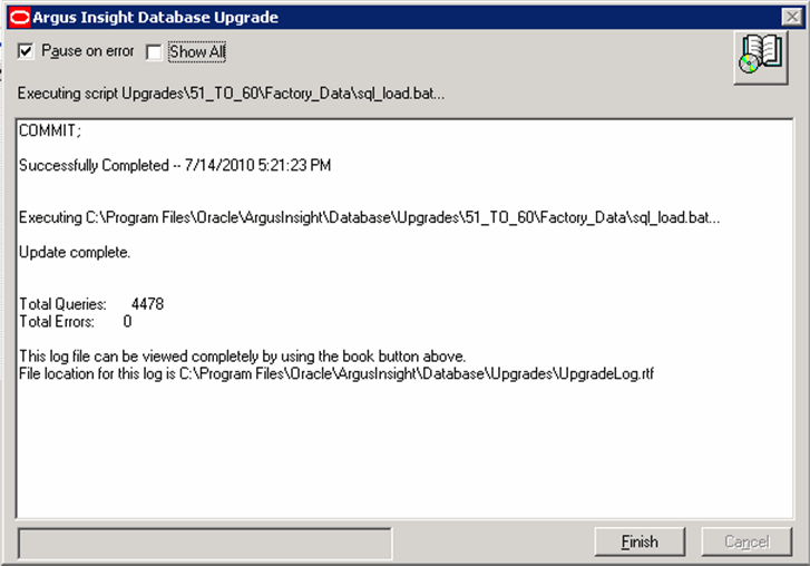
The system opens the following screen. Click Finish to complete the upgrade.
|
Note: If you have upgraded Argus Insight 6.0 using an Argus Safety version earlier than the 6.0 version, and have then upgraded Argus Safety to its 6.0 version, you need to execute the User Password Update Utility. To use this utility, click the AIPwdUpdate.exe present in the \Oracle\Database\DBInstaller folder. |
Execute the following steps if you wish to use the Upgrade utility:
Go to the <Insight_Install_Path>\Database\DBInstaller folder and double-click AIPwdUpdate.exe. The following screen is displayed.
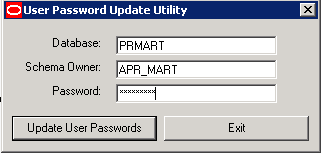
Enter the database name and click Update User Passwords. On successful update, the following dialog is displayed.
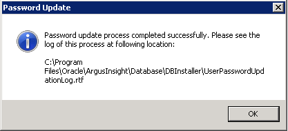
Click OK. The password process has been updated successfully.
Use the following procedure to validate the database schema.
Click Schema Validation to validate the schema.

When the system opens the following dialog box, enter the SYSTEM password and MART instance name and click OK.

When the system opens the following dialog box, click Browse to the right of the Validation CTL Folder and File field.
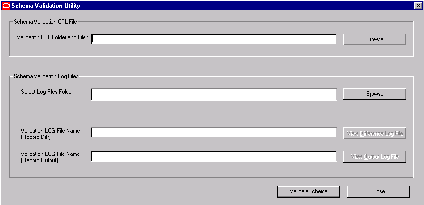
When the system opens the following window, select the validation CTL file. Click Open.
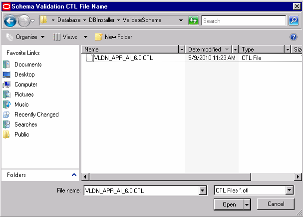
When the system redisplays the following dialog box, click Browse to the right of the Select Log Files Folder field.
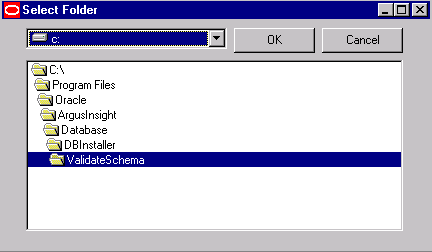
When the system opens the dialog box, select the Log files folder. Click OK.
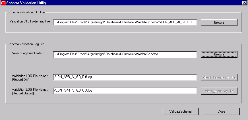
When the system redisplays the following dialog box, click Validate Schema.
The system displays a series of command screens as follows. Press Enter when prompted to do so.
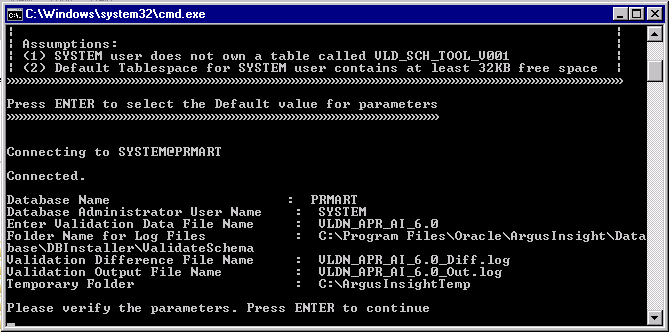
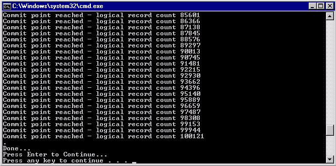
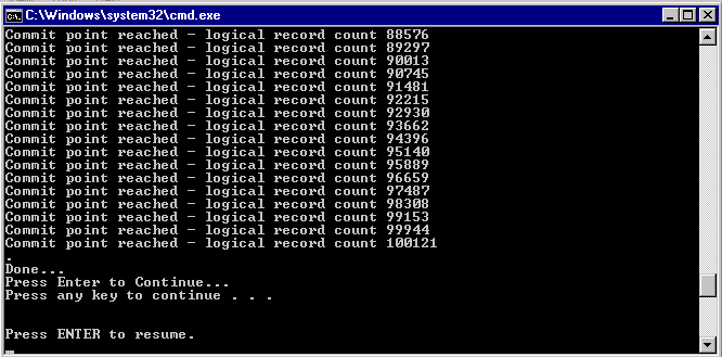
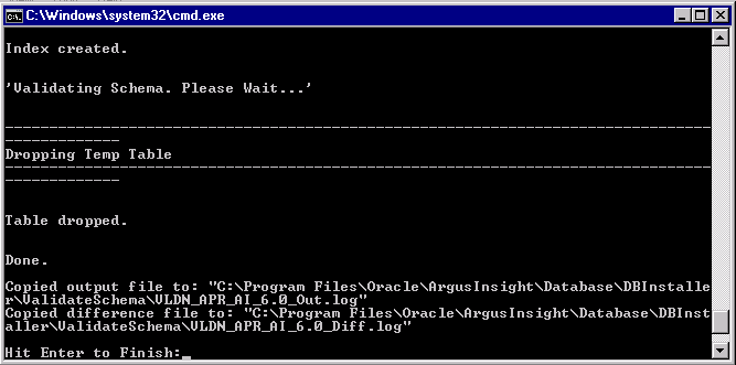
When the system opens the following dialog box, click OK.

When the system displays the log file, verify the log file for any schema discrepancies.
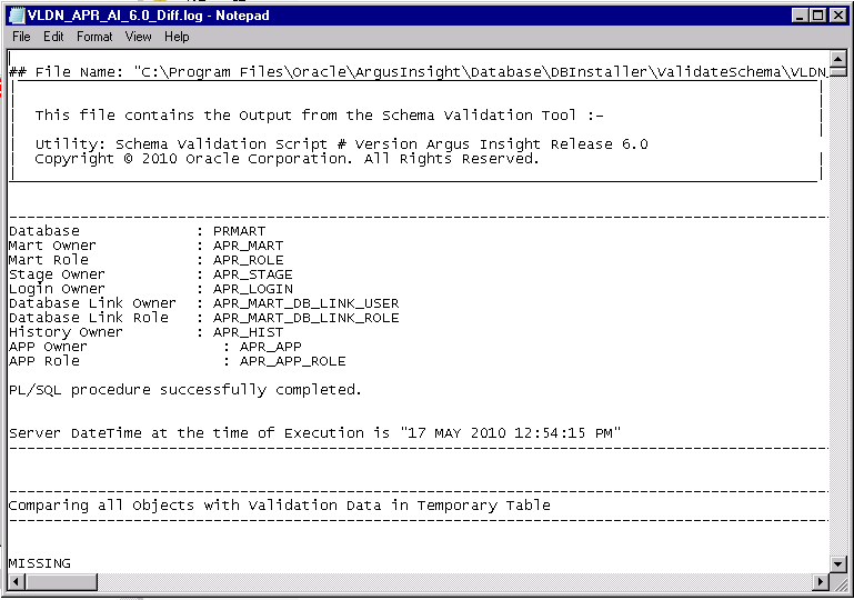
Use the following procedure to create the database link from the Argus Safety database to the Argus Insight database.
Go to Start>Programs>Oracle>Argus Insight>Schema Creation Tool.
Click Argus DBLink.

When the system opens the following dialog box, enter the information for the Argus Safety database. Click OK.
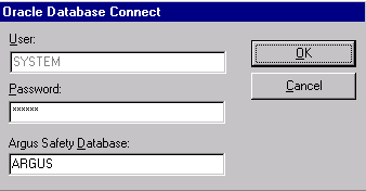
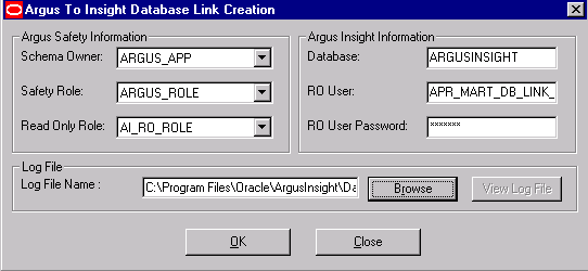
When the system opens the following dialog box, enter the following:
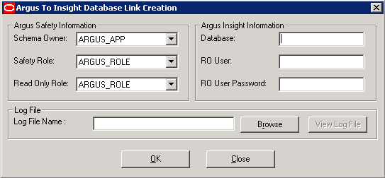
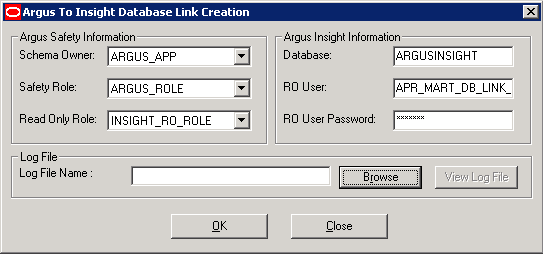
Under Argus Safety Information:
Select the Argus Safety Schema Owner in the Schema Owner field.
Select the Argus Safety role in the Safety Role field.
Select the Insight_RO_Role in the Read Only Role field.
Under Argus Insight Information:
Enter the name of the Argus Insight database in the Database field.
Enter the name of the RO user in the RO user field.
Enter the password for the RO user in the RO User Password field.
Click Browse.
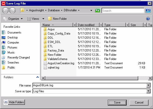
When the system opens the following window, select the Log File for storing the DBLink creation information. Click Save.
When the system returns to the following dialog box, click OK.
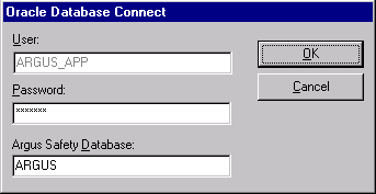
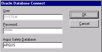
When the system opens the following dialog boxes:
Enter the ARGUS_APP database information. Click OK.
Enter the SYSTEM database information. Click OK.
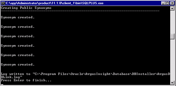
When the system opens the following command screen, press Enter to finish.
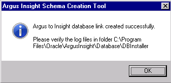
When the system opens the following dialog verify the log files. Click OK.
This section provides information about configuring the Argus Insight application and the Argus Insight scheduling service.
Use the following procedure to set the profile switches for Argus Insight. If you need information about setting common profile switches, see the CMN_PROFILE Guide (CMN_PROFILE.pdf)
Log on with administrative rights to a computer, from where you can access the Argus Insight application.
Start Internet Explorer.
In the Address bar, type the URL http://<Argus Insight Web Server Name>:8084/default.asp and press Enter.
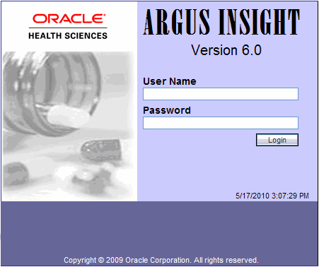
When the system presents the login screen, enter the default administrator user name as administrator and the password as password.
|
Note: If you have logged-in to the system for the first time, it is recommended that you change your login credentials. For account security reasons, ensure that you change your password after logging in for the first time. |
Click the Tools button in the upper-right corner of the main page. The Administration Tools page appears.
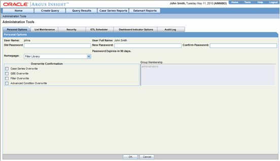
In the Administration Tools page, click the List Maintenance tab.
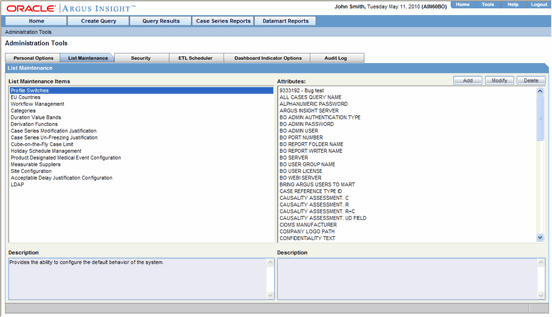
Use the following procedure to configure profile switches.
Select Profile Switches from the List Maintenance Items list.
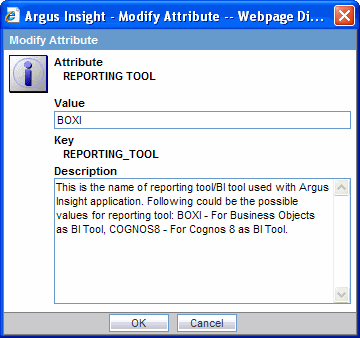
Set the value of Reporting Tool through List Maintenance as BOXI:
Select COMPANY LOGO PATH from the Attributes list.
Click Modify. The Modify Attribute window appears.
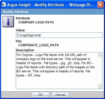
Enter the company logo path in the Value field.
This is the path of the image from the BOXI Server.
|
Note: The recommended logo settings for the reports are:
|
Click OK to save the modification and return to the List Maintenance page.
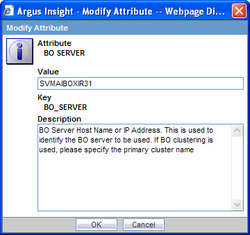
Select BO SERVER from the Attributes list.
Click Modify. The Modify Attribute window appears.
Enter the BO Server name or IP Address in the Value field.
|
Note: In case of a Single Server Environment (i.e. Argus Insight and Business Objects are hosted on the same server), it is mandatory to enter the IP address, to avoid problems when accessing the Report writer and Cubes. These problems may be caused due to the Session interference of Argus Insight and Business Objects Web Application. |
Click OK to save the modification and return to the List Maintenance page.
Select BO Admin User from the Attributes list.
Click Modify. The Modify Attribute window appears.
Enter the BO Admin User in the Value field.
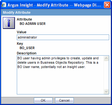
Click OK to save the modification and return to the List Maintenance page.
Select BO Admin Password from the Attributes list and click Modify.
Enter the BO Admin Password in the Value field. This should correspond with BO Admin User entered in the preceding step.
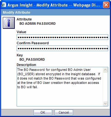
Click OK to save the modification and return to the List Maintenance page.
|
Note: Ensure that the password is consistently updated when the BO User ID/password is changed in the BO Server. |
Select ARGUS INSIGHT SERVER from the Attributes list.
Click Modify. The Modify Attribute window appears.
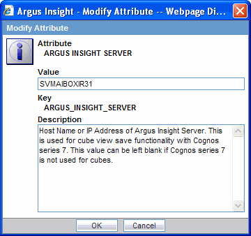
Enter the Argus Insight Web Server name in the Value field.
Click OK to save the modification and return to the List Maintenance page.
Select BO Port Number from the Attributes list and click Modify.
When the Modify Attribute dialog box opens, enter the value of the BO Port Number in the Value text box.
Click OK to save the modification and return to the List Maintenance page.
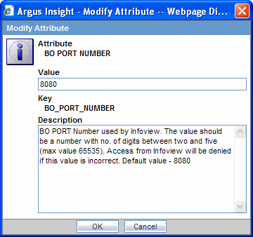
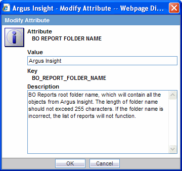
Select BO Report Folder Name from the Attributes list and click Modify.
When the system opens the Modify Attribute dialog box, enter the value of the BO Report Folder Name in the Value text box.
Click OK to save the modification and return to the List Maintenance page.
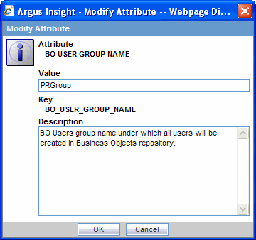
Select BO User Group Name from the Attributes list and click Modify.
When the system opens the Modify Attribute window, enter the value of the BO User Group Name in the Value text box.
Click OK to save the modification and return to the List Maintenance page.
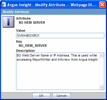
Select BO WebI Server from the Attributes list and click Modify.
When the system opens the Modify Attribute dialog box, enter the value of the BO WebI Server in the Value text box.
Click OK to save the modification and return to the List Maintenance page.
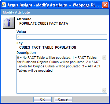
Select Populate Cubes Fact Data from the Attributes list and click Modify.
Enter the value of the Populate Cubes Fact Data in the Value text box.
Click OK to save the modification and return to the List Maintenance page.
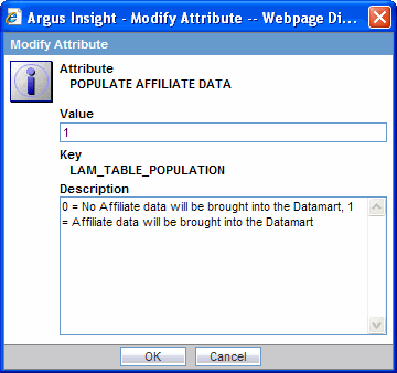
Select Populate Affiliate Data from the Attributes list and click Modify.
When the system opens Modify Attribute dialog box, enter the value of the Affiliate Data in the Value text box.
Click OK to save the modification and return to the List Maintenance page.
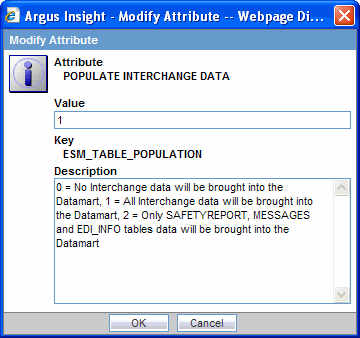
Select Populate Interchange Data from the Attributes list and click Modify.
Enter the value of the Interchange Data in the Value text box.
Click OK to save the modification and return to the List Maintenance page.
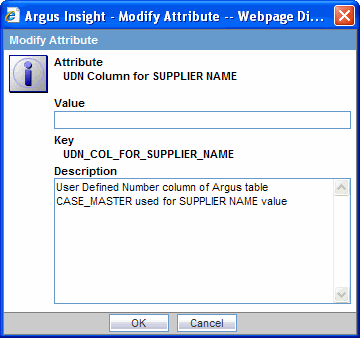
Select UDN Column for Supplier Name from the Attributes list and click Modify.
Enter the value of the UDN Column for Supplier Name in the Value text box.
|
Note: Configure the UDN Column for Supplier Name if you are using the Supplier Performance Report. |
Click OK to save the modification and return to the List Maintenance page.
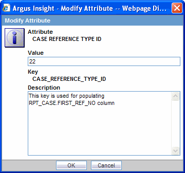
Select Case Reference Type ID from the Attributes list and click Modify.
Enter the value of Case Reference Type ID, as per business requirements.
|
Note: Configure the Case Reference Type ID if you are using the Monthly Manufacturing Report. |
Click OK to save the modification and return to the List Maintenance page.
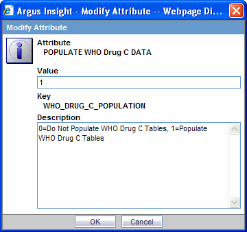
Select Populate WHO Drug C Data from the Attributes list and click Modify.
Enter the value of the Populate WHO Drug C Data in the Value text box. To populate the WHO Drug C tables, enter the value as 1, else keep it as 0.
Click OK to save the modification and return to the List Maintenance page.
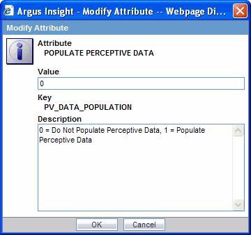
Select Populate Perceptive Data from List Maintenance tab to populate the perceptive data.
Enter the Perceptive Data Population switch value in the Value field.
Click OK to save the modification and return to the List Maintenance tab.
Set the following switches to "1" only if you are using the corresponding reports as mentioned with the switch name
POPULATE RPT_REG_REPORTS COLUMNS:
0 = Extra columns of table RPT_REG_REPORTS will NOT be populated, 1 = Extra columns of table RPT_REG_REPORTS will be populated (These columns are used in Business Objects version, Compliance category report "Regulatory Submission and Distribution Compliance")
POPULATE NARRATIVE LANGUAGES TABLE:
0 = Tables RPT_CNL_MLINGUAL and RPT_CNL_ENGLISH will NOT be populated, 1 = Tables RPT_CNL_MLINGUAL and RPT_CNL_ENGLISH will be populated. These tables are used by General Category Reports 'Case Narrative Listing - Multilingual" and "Case Narrative Listing - English".
POPULATE DATA QUALITY INDICATOR:
0= Table DATA_QUALITY_INDICATOR required for Data Quality Indicator report will NOT be populated, 1 = Table DATA_QUALITY_INDICATOR required for "Data Quality Indicator report" will be populated.
Note: Ensure that you run the initial ETL after updating any of the ETL Population switches. The only exception to this is the Populate WHO Drug C Data switch, for which you need not run the initial ETL.
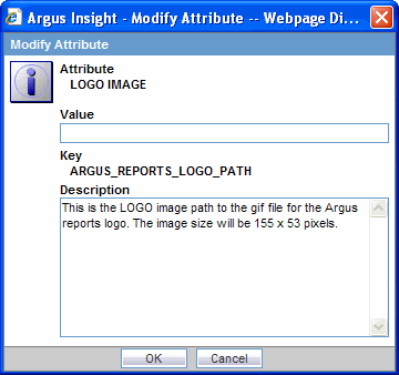
Select Logo Image from attributes List on the List Maintenance tab to configure the logo for Argus Reports.
Enter the logo image path from insight web server in the Value field. For example, enter the Value as C:\apr_logo.gif. Ensure that the size of this file is 155x53 pixels.
Click OK to save the modification and return to the List Maintenance tab.
Select Days to Lock from the Attributes list and click Modify.
Enter 9 in the Value text box.

Click OK to save the modification and return to the List Maintenance page.
Click the WHO DRUG BROWSER FORMAT.
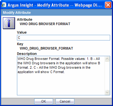
The system uses this entry to open the WHO Drug B/C Format, as configured in the screen shown above.
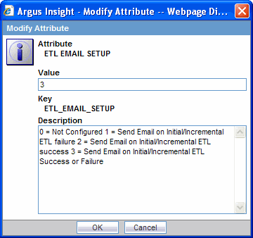
Configure the ETL EMAIL SETUP for receiving emails about Initial or Incremental ETL status.
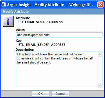
Enter the address of the sender for receiving emails about ETL status in Value.
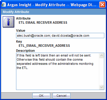
Enter the address of the receiver for receiving emails about ETL status in Value.
In the List Maintenance page, select Use BO Job Server from the Attributes list. Click Modify.
Enter the appropriate value and click OK.

Set the value as 1 and click OK.
|
Note: When this switch is set to 1, it forces the report scheduling to use BO job server for all the scheduled reports using Argus Insight.User will receive an email along with report PDF/XLS after successful creation of scheduled report. User will receive a link for the scheduled report if the report size is bigger than the configured attachment limit. This limit is defined in mailconfig.xml file. |
The following profile switch configuration steps need to be performed only by customers who are using the validation package supplied by Oracle.
From the List Maintenance page, you can map all the site-specific workflow states to these default groups for the purpose of grouping outputs of certain reports:
Compliance Metrics - Data Entry Performance -all workflow states that are considered as Data Entry in Data Entry Performance Over Time Report
Compliance Metrics - HQ Acceptance -all workflow states that indicate Review Completion in Data Entry Performance Over Time Report
Manufacturing Metrics - Distribution States -all workflow states that are considered as Distribution in Manufacturing Monthly Report
Performance Metrics - External Data Entry -all workflow states that are considered as Data Entry in External Clinical QC Report
Performance Metrics - External QC -workflow states that are considered for a secondary QC check in External Clinical QC Report
Performance Metrics - HQ Acceptance -all workflow states that indicate QC Review Completion in External Clinical QC Report
QC Metrics - HQ Acceptance -all workflow states that indicate QC Review Completion in Regulatory Submission and Distribution Compliance Report and Process Performance Report
Workflow Metrics - Archiving States- all workflow states that are considered as Archived/Closed in Argus
Workflow Metrics - Data Entry Complete- all workflow states that indicate completion of data entry in Argus
Workflow Metrics - Assessment Complete- all workflow states that indicate completion of event assessment in Argus
Workflow Metrics - Approval Complete- all workflow states that indicate that the case is ready for reporting after being locked in Argus
Although these mappings are pre-configured at the time of installation of Argus Insight, you can modify them by adding or removing workflow states from a group as required. However, you cannot add more groups or delete existing ones.
Select Workflow Management from the List Maintenance Items list.
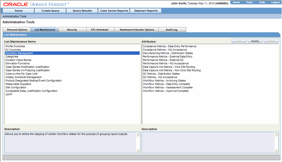
Select Workflow Metrics - Archiving States from the Attributes list.
Click Modify.
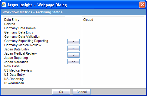
Select Germany Expediting Reporting, US-Reporting and Japan Reporting from the list on the left and click > to add them as Archiving States.
Click OK to save the modification and return to the List Maintenance page.
Select Workflow Metrics - Data Entry Complete from the Attributes list.
Click Modify.
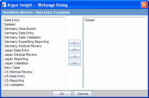
Select Germany Data Validation, US-Validation, and Japan Validation from the list on the left and click > to add them as Data Entry Complete.
Remove the Closed item from the list on the right by selecting Closed and clicking <.
Click OK to save the modification and return to the List Maintenance page.
Select Workflow Metrics - Assessment Complete from the Attributes list in the List Maintenance page.
Click Modify.
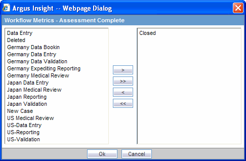
Select Germany Medical Review, US Medical Review, and Japan Medical Review from the list on the left and click > to add them as Assessment Complete.
Remove the Closed item from the list on the right by selecting Closed and clicking <.
Click OK to save the modification and return to the List Maintenance page.
Select Workflow Metrics - Approval Complete from the Attributes list.
Click Modify.
Select Germany Medical Review, US Medical Review, and Japan Medical Review from the list on the left and click > to add them as Approval Complete.

Remove the Closed item from the list on the right by selecting Closed and clicking <.
Click OK to save the modification and return to the List Maintenance page.
Select Compliance Metrics - Data Entry Performance from Attributes in List Maintenance Items - Workflow Management.
Click Modify.
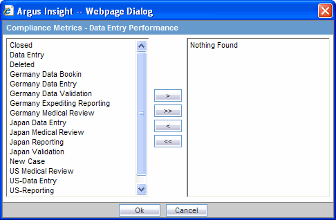
Make the required selections by selecting the required entities from the list on the left and clicking > to move them individually or clicking >> to move all of them together.
Alternatively, click the entities to be de-selected from the list on the right and click < to move them individually or click << to move all of them together.
Click OK to save the modification and return to the List Maintenance page.
Select Compliance Metrics - HQ Acceptance from the Attributes List Maintenance Items - Workflow Management.
Click Modify.
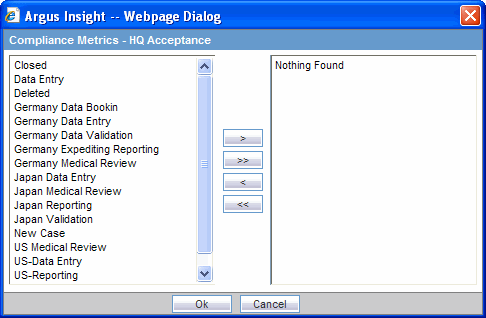
Make the required selections by selecting the required entities from the list on the left and click > to move them individually or click >> to move all of them together.
Alternatively, click the entities to be de-selected from the list on the right and click < to move them individually or click << to move all of them together.
Click OK to save the modification and return to the List Maintenance page.
Select Manufacturing Metrics - Distribution States from Attributes in List Maintenance Items - Workflow Management.
Click Modify.
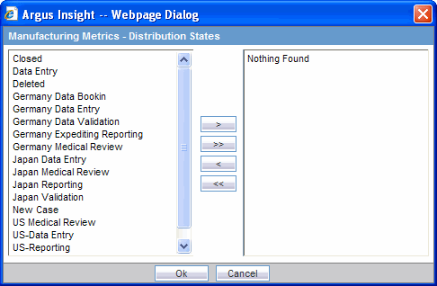
Make the required selections by selecting the required entities from the list on the left and click > to move them individually or click >> to move all of them together.
Alternatively, click the entities to be de-selected from the list on the right and click < to move them individually or click << to move all of them together.
Click OK to save the modification and return to the List Maintenance page.
Configuring Performance Metrics - External Data Entry
Select Performance Metrics - External Data Entry from Attributes in List Maintenance Items - Workflow Management.
Click Modify.
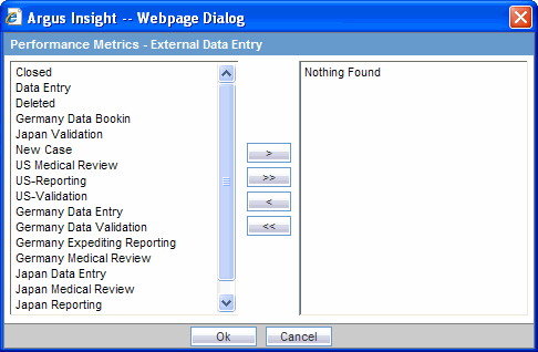
Make the required selections by selecting the required entities from the list on the left and click > to move them individually or click >> to move all of them together.
Alternatively, click the entities to be de-selected from the list on the right and click < to move them individually or click << to move all of them together.
Click OK to save the modification and return to the List Maintenance page.
Select Performance Metrics - External QC from Attributes in List Maintenance Items - Workflow Management.
Click Modify.
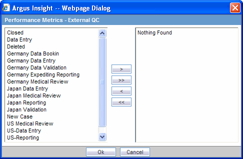
Make the required selections by selecting the required entities from the list on the left and click > to move them individually or click >> to move all of them together.
Alternatively, click the entities to be de-selected from the list on the right and click < to move them individually or click << to move all of them together.
Click OK to save the modification and return to the List Maintenance page.
Select Performance Metrics - HQ Acceptance from Attributes in List Maintenance Items - Workflow Management.
Click Modify.
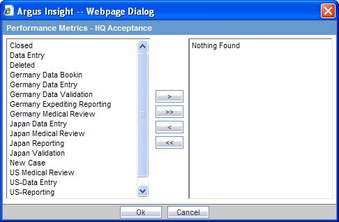
Make the required selections by selecting the required entities from the list on the left and click > to move them individually or click >> to move all of them together.
Alternatively, click the entities to be de-selected from the list on the right and click < to move them individually or click << to move all of them together.
Click OK to save the modification and return to the List Maintenance page.
Select QC Metrics - HQ Acceptance from Attributes in List Maintenance Items - Workflow Management.
Click Modify.
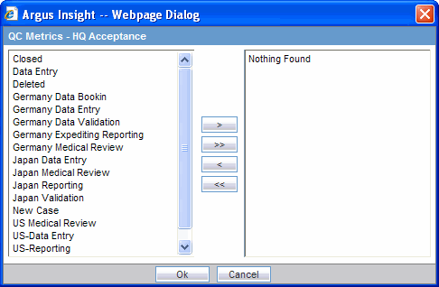
Make the required selections by selecting the required entities from the list on the left and click > to move them individually or click >> to move all of them together.
Alternatively, click the entities to be de-selected from the list on the right and click < to move them individually or click << to move all of them together.
Click OK to save the modification and return to the List Maintenance page.
In Argus Insight, the time values (entered in Argus Safety) in the Product Tab > Drug Duration of Administration, Events Tab > Time to Onset from First Dose, and Events Tab > Time to Onset from Last Dose fields can be mapped to specific ranges called Duration Value Bands. This enables you to specify querying criteria based on ranges instead of specific values for the above fields.
The Duration Values Bands item in the List Maintenance page lets you configure the duration value bands in the hours, days, weeks, months, and years categories. In each category, you can specify multiple ranges by entering maximum and minimum value for each range item. Any value that falls within a configured range will map to that range.
|
Note: Duration Value Band configuration needs to be done before running the Initial ETL.If Duration Value Bands are modified after Initial ETL, you have to re-run the Initial ETL. |
Use the following procedure to configure duration band values.
In the List Maintenance tab page, select the Duration Values Bands item from the List Maintenance Items list.
The Attributes list displays the existing categories. These are default categories and cannot be modified.
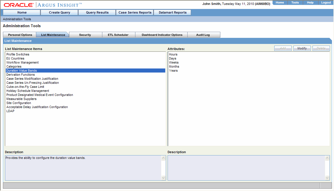
Select an Attributes category.
Click Modify.
The Duration Value Bands Configuration dialog box appears with the factory-configured ranges:
The Label column represents the name of the range.
The Lower Range (>=) and Higher Range (<) columns contain the minimum and maximum values, respectively.
Modify the values, as appropriate.
In the Duration Value Bands Configuration dialog box, you can delete an existing range by clicking the Delete icon or you can modify a range by editing the values in the Higher Range (<) columns.
Note that the lowest band cannot be deleted.
Additionally, the highest value band includes values that are greater than the highest range value that you specify.
To add a range, enter a higher range compared to the previous highest range in Higher Range (<) and press TAB. This adds a new row.
If you delete an intermediate range, the highest value of the deleted range is automatically converted to the lowest value in the next range. However, the range labels do not change.
Click OK to save the changes.
Argus Insight lets you create a new List Maintenance item and derive specific cases to this item based on case attributes. These attributes are supplied to the system as an SQL.
For example, you can create a new List Maintenance item called Report Type 1 and derive to this item, all the cases that have the Report Type attribute as Spontaneous, Literature, and Compassionate Use. As a result, the Report Type 1 List Maintenance item appears as an option in the query tool interface corresponding to the Report Type attribute. When you select the Report Type 1 from the Report Type list and execute your query, the system returns only those cases that have the report type attribute as Spontaneous, Literature, and Compassionate Use.
You may also create a further specialized List Maintenance item called Report Type 1 US and derive to this item, all the cases that have the Report Type attribute as Spontaneous, Literature, and Compassionate Use and the Country of Incidence attribute as United Sates.
|
Note: There can be situations where two different List Maintenance items you create contain similar attributes in the SQL criteria. In this case, you can assign a priority level to individual List Maintenance items. The priority level determines which LM item SQL is executed first. |
Use the following procedure to configure the derivation functions.
In the List Maintenance tab page, select the Derivation Functions item from the List Maintenance Items list.
The Attributes list displays the existing categories.
This is a default category and cannot be modified.
Select the category All Derivations and click Modify. 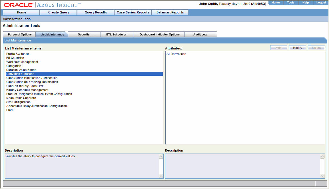
The system opens the Derivation Fields dialog box.
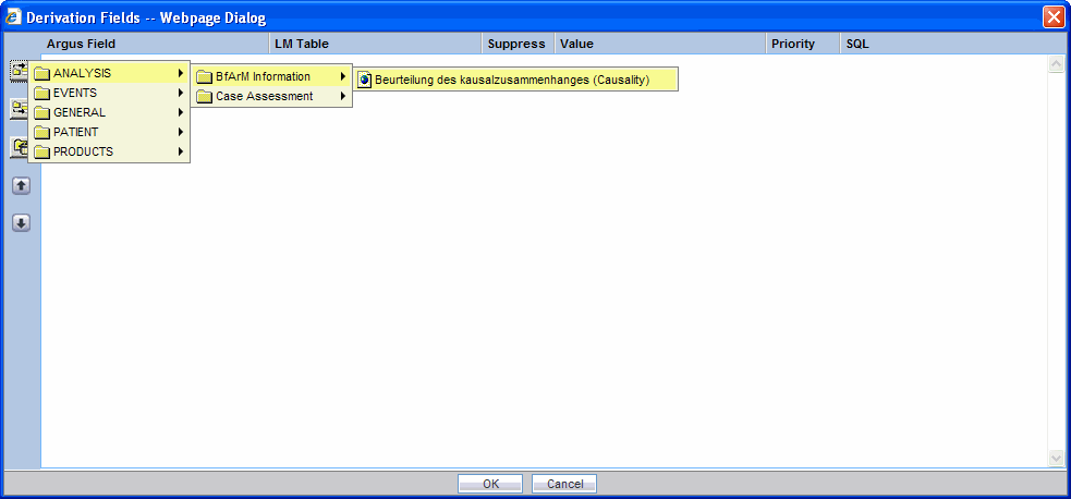
Use the following icons to add/delete/rearrange rows in the Derivation Fields window.
| Click on... | To... |
 |
add a row above |
 |
add a row below |
 |
delete a row |
 |
arrange rows |
Refer to the brief descriptions for the explanation of the fields as displayed in the Derivation Fields window
The Argus Field Mapping derivation rules are applicable as shown below:
ANALYSIS->BfArM Information -> Causality
ANALYSIS->Case Assessment -> Listedness Determination
ANALYSIS->Case Assessment -> Case Outcome
ANALYSIS->Case Assessment -> Case Seriousness
EVENTS->Event Information -> Lack of Efficacy
GENERAL->General Information ->Report Type
GENERAL->General Information -> Pregnancy
PATIENT->Patient Information -> Age Group
PATIENT->Patient Information -> Patient weight BMI desc
PATIENT->Patient Information -> Patient Gender
PRODUCTS->Product Drug -> Derived Overdose
PRODUCTS->Product Drug -> Derived Drug Abuse
PRODUCTS->Product Drug ->Derived Drug Interaction
PRODUCTS->Product Drug ->Last daily dose
|
Note: Age Group, Causality, Last daily dose and Report Type are comma separated Derivation rules. |
| Field | Description |
|---|---|
| LM Table | This field is the table name of the selected Argus field (i.e., automatically populated). |
| Suppress | Suppress functionality is available for fields associated with the list maintenance data. When suppress is enabled for a field, the corresponding list maintenance values which are not present in any case are deleted and thus not available for querying.
Note: This is applicable only if the condition specified in the SQL text box covers all the cases having the selected LM field. |
| Value | This textbox captures the value for the new derivation field.
For the following rules the system expects the user to enter the rule's new value as a comma separated value. Make sure that the values for these rules are entered as mentioned below. Unexpected results and/or ETL error might result if the values are not entered as specified. |
| Age Group rule: VALUE, GROUP_LOW, GROUP_HIGH
Parameter name and description is given below:
Example: NewAgeGroup, 25, 50 If you do not want to specify the High Value then the comma is mandatory in the end. For example, Unknown, 70, |
|
| Causality: VALUE, REPORTABILITY
Parameter name and description is given below:
Example: NewCausality, 1 |
|
| Last Daily Dose: VALUE, DAILY_DOSE_SORTING_ORDER
Parameter name and description is given below:
Examples: Example: 1 -> 0to1, 1 Example: 2 -> 2to3, 2 Example: 3 -> 5to8, 3 |
|
| Report Type: VALUE, INC_LIT, INC_TRIAL, ABRV
Parameter name and description is given below:
Example: NewReportType, 0, 1, NRT |
|
| Priority | This field captures the priority for a list of derivation rules applied to a single LM field. The value can be from 1 to 255
The priority for derivation rules applicable to a single LM filed should be unique. |
| SQL | In this textbox we specify the SQL statement to capture the cases for which the derivation rule is applicable. |
| LM Table | This field is the table name of the selected Argus field (i.e., automatically populated). |
| Suppress | Suppress functionality is available for fields associated with the list maintenance data. When suppress is enabled for a field, the corresponding list maintenance values which are not present in any case are deleted and thus not available for querying.
Note:This is applicable only if the condition specified in the SQL text box covers all the cases having the selected LM field. |
| Value | This textbox captures the value for the new derivation field.
For the following rules the system expects the user to enter the rule's new value as a comma separated value. Make sure that the values for these rules are entered as mentioned below. Unexpected results and/or ETL error might result if the values are not entered as specified. |
| Age Group rule: VALUE, GROUP_LOW, GROUP_HIGH
Parameter name and description is given below:
Example: NewAgeGroup, 25, 50 If you do not want to specify the High Value then the comma is mandatory in the end. For example, Unknown, 70, |
|
| Causality: VALUE, REPORTABILITY
Parameter name and description is given below:
Example: NewCausality, 1 |
|
| Last Daily Dose: VALUE, DAILY_DOSE_SORTING_ORDER
Parameter name and description is given below:
Examples: Example: 1 -> 0to1, 1 Example: 2 -> 2to3, 2 Example: 3 -> 5to8, 3 |
|
| Report Type: VALUE, INC_LIT, INC_TRIAL, ABRV
Parameter name and description is given below:
Example: NewReportType, 0, 1, NRT |
|
| Priority | This field captures the priority for a list of derivation rules applied to a single LM field. The value can be from 1 to 255
The priority for derivation rules applicable to a single LM filed should be unique. |
| SQL | In this textbox we specify the SQL statement to capture the cases for which the derivation rule is applicable.
The SQL query configured against a rule should only have the primary key column name(s) of the field in the SELECT clause. It should also not contain the table name. Example:
Make sure that there is only one space after the select clause in the SQL query. Example:
Make sure that no oracle keyword (such as distinct) is used after the select clause in the SQL query. Example:
|
Log on to the Argus Insight Server as an Admin user.
Open the MailConfig.xml in Notepad from this location: <Argus Insight Installation Path>/<Bin folder on the Argus Insight Web Server>
Modify the tags in the MailConfig.xml file as follows:
| Existing Tag | Modify To |
| <AdminId>Administrator@oracle.com</AdminId> | <AdminId><EmailID></AdminId> where EmailID is the email ID used for sending Scheduled Reports |
| <epwd>Password</epwd> | <epwd><Email Password></AdminId> where Email Password is the email access password for the email ID provided in <AdminId><EmailID></AdminId>
If you want to send emails to external domains, provide a valid password. Else, you can enter any value as password. Secure Connections require a valid password. |
| <SMTPServer>172.16.10.46</SMTPServer> | <SMTPServer><Mail Server IP></SMTPServer> where Mail Server IP is the IP address of your Email Server |
| <Authenticate>NO</Authenticate> | <Authenticate> User Authentication for sending Emails </Authenticate>
If a secure connection is needed ,mark this entry as YES. If a non- secure connection is needed, mark this as NO. Example: Dominos server should mark this entry as no and Microsoft Exchange server should mark this entry as either yes or no |
| <MaxMailSizeKB>1024</MaxMailSizeKB> | Maximum size allowed for mail attachment on email server. |
| <SMTPPORT>25</SMTPPORT> | <SMTPPORT><Port Number></SMTPPORT>
where Port Number is the SMTP Port Number |
| <SMTPConnTimeOut>100</ SMTPConnTimeOut> | < SMTPConnTimeOut><TimeOut in Seconds></ SMTPConnTimeOut >
where Timeout is the time in seconds for SMTP Connection Timeout. |
| <ReplyTo>administrator@oracle.com</ReplyTo | <ReplyTo><EmailID></ReplyTo where EmailID is the id to which the reply will be sent via e-mail |
| FailedRecipientsMailTo | <FailedRecipientsMailTo>EmailID</FailedRecipientsMailTo>
Configure the email address of user who will receive email for information regarding un-delivered emails due to invalid email id or any other error. |
| <OracleService_InsightURL> | <OracleService_InsightURL> contains URL for Argus Insight application for accessing reports which can not be sent to configured mail id due to mail size limit. |
Save the file and close it.
Starting Argus Insight Service:
Go to Start->Run on the Argus Insight web server
Type Sevices.msc in the textbox and press Enter.
Services window will be displayed on the screen.
Go to Argus Insight Service.
Right click the Argus Insight Service and select properties.
Set the startup type as Automatic.
Start the Argus Insight Service.
Press OK to close the Argus Insight Service Properties dialog window.
|
Note: For changing the interval of different service tasks, please modify the entries in Service.config file present under Bin folder of Insight. All the times mentioned in this file are in seconds. |
IMPORTANT! Ensure that the user who runs this service has administrative privileges. If the user does not have administrative privileges, either the Scheduled CIOMS Reports might not return or an LDAP user might not be able to log in to the Argus Insight web application.
Use the information in this section to export and import data. Before importing or exporting data, be aware of the following:
Before importing or exporting to or from a network drive, please verify that you have mapped the network drive. This tool does not support accessing of network drives directly.
Before copying Argus Data, incremental ETL should be completed on Source Insight Database from Source Argus.
It is assumed that the configuration of the instance of Argus used to run Initial and Incremental ETL on the source Insight DataMart will also be copied and applied on the new Argus Instance which will be associated with the new Insight DataMart.
Data has to be imported after loading Factory Data and before running Initial ETL on destination environment.
Use the following procedure to export data.
Go to Start>Programs>Oracle>Argus Insight>Schema Creation Tool.
Click Export Data.

The Export Utility dialog appears.
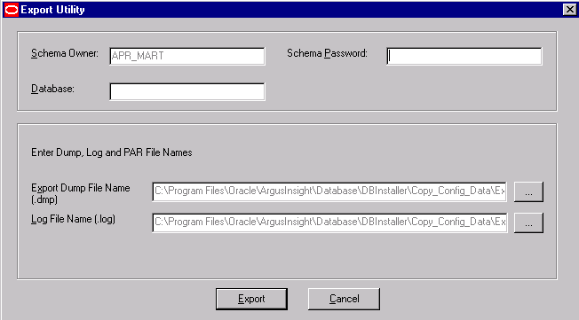
Provide inputs for the Schema Owner, Password and the Database.
To retain the default values of the Export Dump, Log and PAR files, click Export.
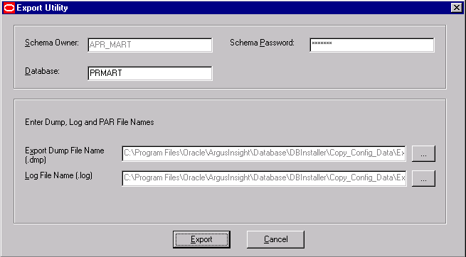
To configure the export file name and location, click the button, next to the Export Dump File Name to open the Export Dump File dialog box.
Navigate to the location in this dialog and provide the export file name and click Save.
Configure the Log File Name similarly, by following steps 5a, 5b and 5c.
To retain the default file name, click Export to continue.
|
Note: Do not change the parameter file name and location. |
When you click Export, the system opens the following command screens.
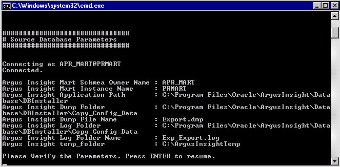
Press Enter to continue.
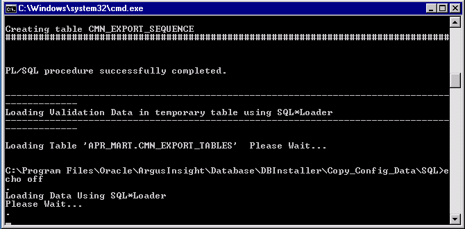
When the system opens the Import Dump Information dialog box stating that the Configuration Data has been exported, click OK.

When the system opens the Argus Insight Schema Creation Tool dialog box, lick OK and verify the log files are at the location displayed in the dialog.
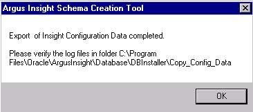
Use the following procedure to import data.
Go to Start>Programs>Oracle>Argus Insight>Schema Creation Tool. Click Import Data.

When the system opens the Import Utility dialog, provide inputs for the Schema Owner, Password and the Database.
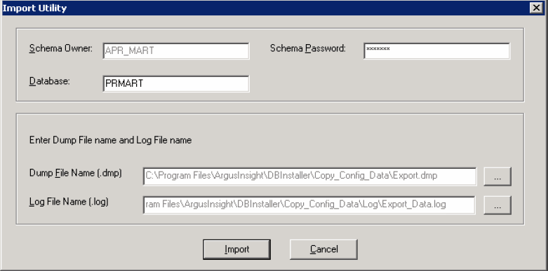
To configure the Dump file name and location, click the button next to the Dump File Name.
When the system opens the Import Dump File dialog box, navigate to the appropriate location in the dialog and select the Dump File Name.
To retain the default log file, click Import.
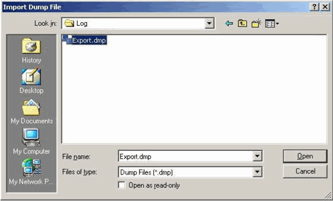
Click Open.
You can configure the Log File Name similarly, by following steps 4, 5, and 6.
To retain the default file name, click Import to continue.
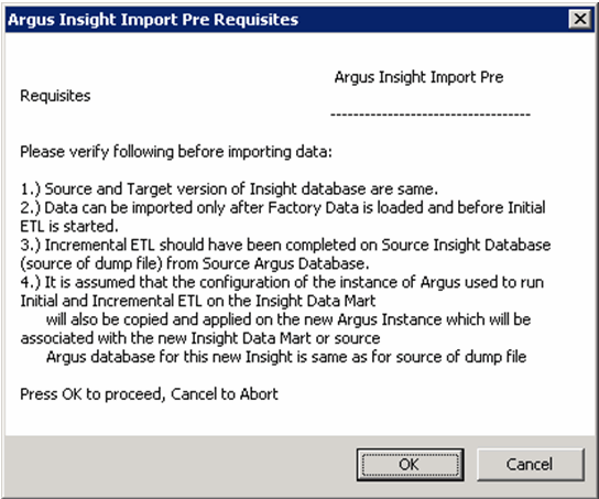
On clicking Import, the following screen appears. Click OK to proceed with the import.
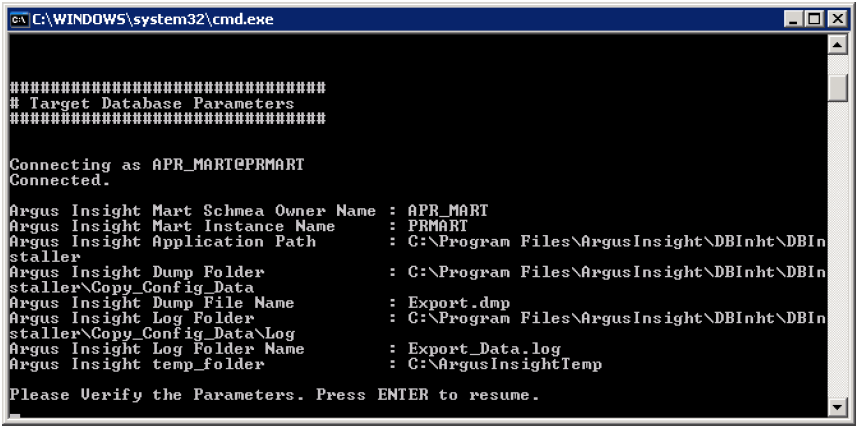
The system imports the data and displays the following command screens..
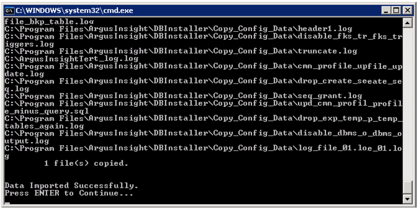
When the system opens the Argus Insight Schema Creation Tool dialog box, click OK.

Verify the log files are at the location displayed in the dialog.
Before running the Initial ETL, verify that Auto extend is set to ON for all the database data files related to Staging and Mart. Before running ETL, be aware of the following:
Do not run incremental ETL for more than 50,000 cases. If the number of cases is greater than 50,000, run the Initial ETL again.
Initial ETL requires a huge amount of Temp space. To prevent data errors, set the temp space to 100 GB. After completing the Initial ETL reset the temp space to 30 GB.
After completing the Initial ETL, the balancing log may show differences between the Argus/Stage and MART table counts. This is because of the derivation rules that are applied onto the datamart.
If this warning appears: "Warning !!! - Could not locate MedDRA-J User in the Argus Database", ignore this warning for all MedDRA tables.
Use the following procedure to run the initial ETL.
Log on to the Argus Insight Web Server as an Admin user.
Select Start > Programs > Oracle > Argus Insight > Schema Creation Tool.
When the system opens the Schema Creation Tool dialog box, click Initial ETL

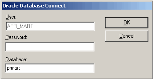
When the system opens the Oracle Database Connect dialog box, enter the APR_MART password and database name in their respective fields. Click OK.
When the system opens the Initial ETL Status dialog box, click Start ETL.
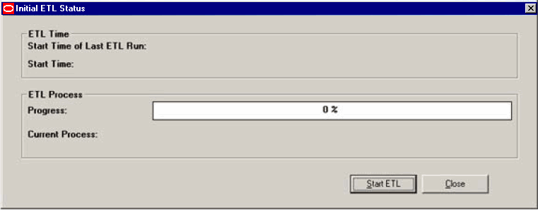
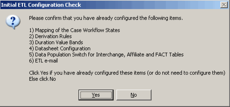
When the system opens the Initial ETL Configuration Check dialog box, click Yes if these items have already been configured.
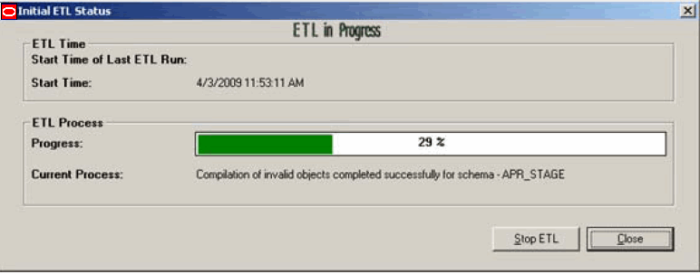
The system presents a processing dialog box showing the ETL start time, current process in execution and the progress bar while ETL is in progress.
|
Note:
|
Initial ETL process completes successfully with 100% displayed in the progress bar.

Click Balancing logs. This button is available after Initial ETL completion.
When the system opens the Balancing Logs dialog box, click OK.
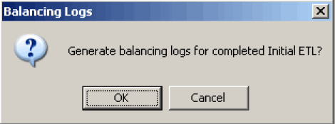
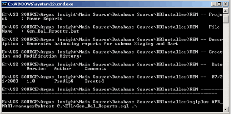
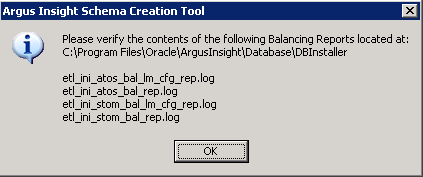
The location of the balancing log reports generated with the report names is shown in the below screen. Click OK.
Click Run ETL (from the Initial ETL Status dialog, as shown in Step 8) if you want to start the Initial ETL process from the beginning after confirmation message and APR_MART password input.
Click Restart ETL to start the Initial ETL process from beginning after confirmation message and APR_MART password input.
Use the following procedure to close the Initial ETL Status dialog box.
Click Close.

When the system opens the Close Application dialog box, click OK.
Use the following procedure to stop the Initial ETL process.
Click Stop ETL.

When the system opens the stop ETL confirmation dialog box, click OK.
The system redisplays the Initial ETL Status dialog box.

Use the following procedure to run the ETL processing from the beginning.
Click Run ETL.
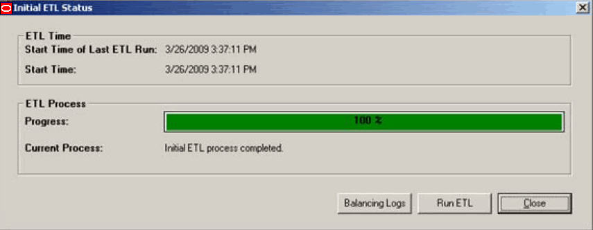
When the system opens the Run ETL dialog box, click OK.
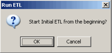
The following dialog is displayed. Enter the APR_MART password and click OK.
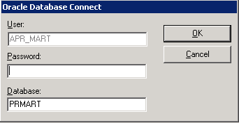
The Initial ETL process starts again from the beginning.
You can choose any of the following options for the failed Initial ETL process.
Click Continue to continue the failed Initial ETL procedure.
Click Ignore to ignore the failed Initial ETL process.
Click Modify Attributes of ETL Data Exclusion if PRE_REQ_CHECK_FLAG switch is set to ABORT.
|
Note: These modifications must be done before running the Initial ETL process. |
Use the following procedure to continue a failed ETL procedure.
Execute the following steps to continue the Initial ETL process from the failed ETL procedure:
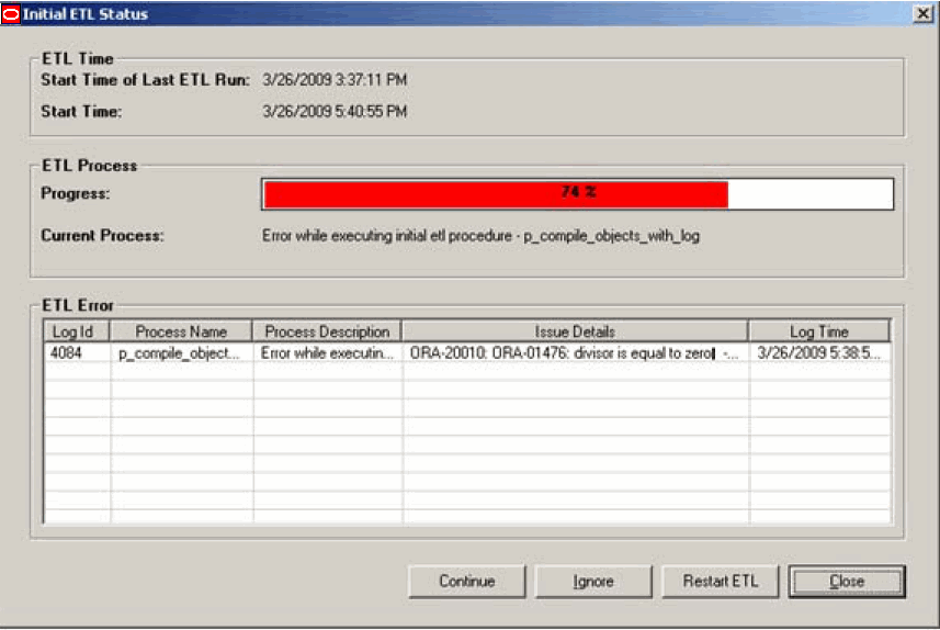
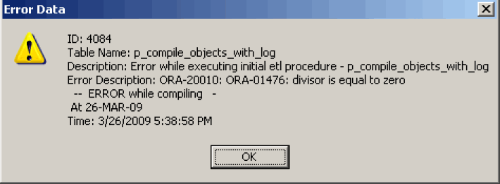
Double-click on the ETL error to view the Error Data dialog containing the details of that error and click OK.
Right-click on the ETL Error and click Copy to copy the error data.
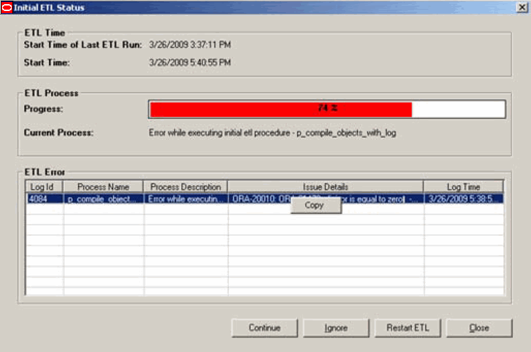
Click Continue to continue the failed ETL process.
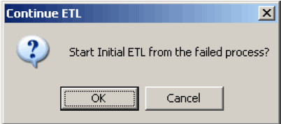
When the Continue ETL dialog opens, click OK.
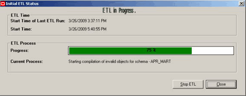
The system continues with the ETL process (if no errors are found).
The system continues executing the initial ETL.
Execute the following steps to start the Initial ETL process by ignoring the failed Initial ETL procedure:
Click Ignore.

When the system opens the Ignore Error confirmation dialog box, click OK.

The system starts the Initial ETL from the next process.

Use the following procedures to modify the ETL Data Exclusion attributes.
Log on to the Argus Insight Web Server as an Admin user.
Select Tools > List Maintenance > Profile Switches > ETL Data Exclusion and click Modify.

When the system opens the Modify Attribute dialog box, enter the appropriate values.
If you want to continue the ETL process but skip the cases with erroneous data, set the value to IGNORE.
If you want to abort the ETL process when it encounters cases with erroneous data, set the value to ABORT.
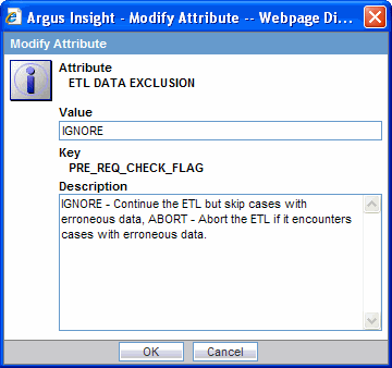
Click OK.
Use the following procedure to start the Initial ETL process from beginning after confirmation message and APR_MART password input.
Click Restart ETL.

When the system opens the Restart ETL dialog box, click OK.

When the system opens the Oracle Database Connect dialog box, enter the APR_MART password and database name in their respective fields. Click OK.

When the system opens the Initial ETL Configuration Check dialog , click Yes if these items have already been configured.

The system proceeds with the ETL process. When the system finishes the ETL process, click Close.


Before importing the repository, delete all the objects in the Argus Insight folder and its corresponding universe and groups. The Argus Insight folder can be accessed by logging into the Central Management Console on the Business Objects Server and clicking on Folders/All Folders.
Use the following procedure to import the repository.
Copy 'Repository.biar' from <Argus Insight Web Server location> \\<Oracle ArgusInsight>\BOXI Repository\ and paste this on the BOXI Server. If BOXI and Argus Insight use the same server, this step is not required.
Open the Start ->All Programs ->Business ->Objects XI release 3.1 ->BusinessObjects Enterprise->Import Wizard and click Next.
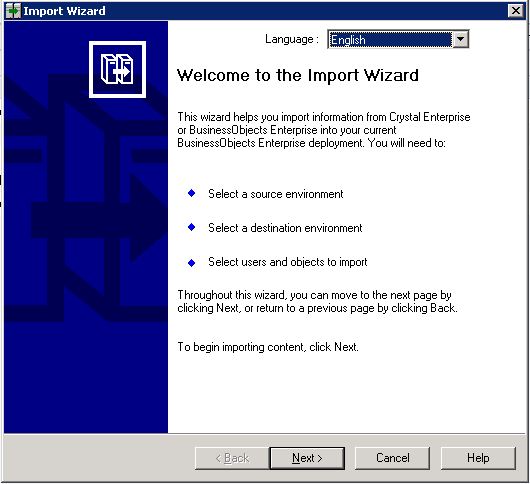
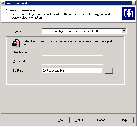
When the system opens the Source environment dialog box, do the following:
Select Business Intelligence Archive Resource (BIAR) File in Source.
Browse to the Repository biar against the BIAR file.
Click Next.
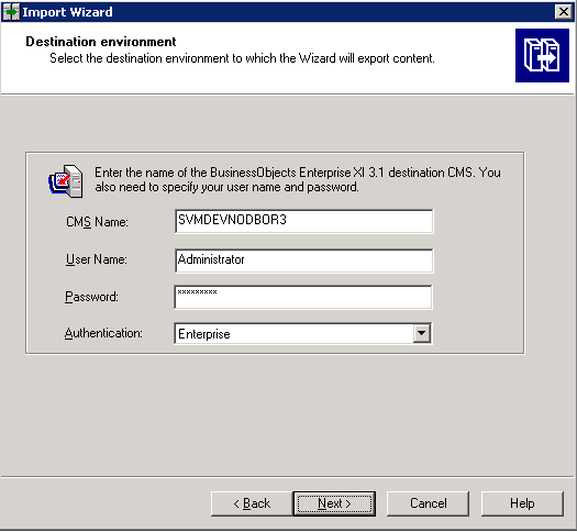
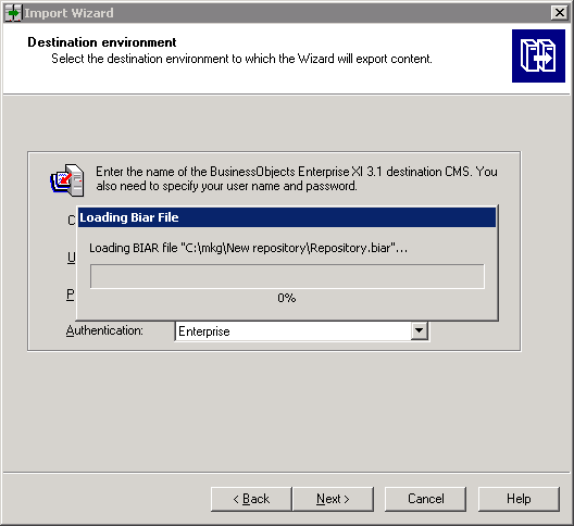
When the system opens the Destination environment dialog box, do the following:
Enter the <BOXI_SERVER> name in CMS Name field.
Enter Administrator in User Name field.
Enter the corresponding password in the Password field.
Click Next.
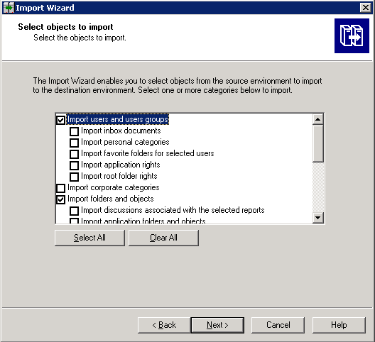
When the system opens the Select objects to import dialog box, check the following:
Check Import users and users groups.
Check Import folders and object.
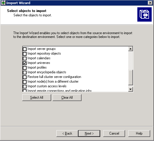
Check Import universes and click Next, as shown below.
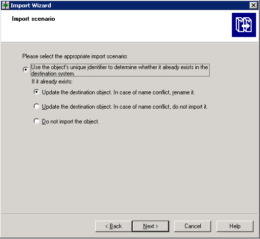
The Import Scenario screen is displayed. Select the appropriate scenario and click Next.
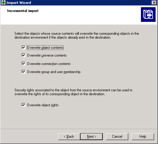
When the system opens the Incremental Import dialog box, check all checkboxes and click Next.
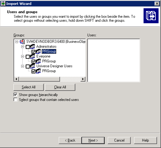
When the system opens the Users and groups dialog box, select the groups you want to import and click Next.
|
Note: The appearance of the preceding dialog box depends on the environment and on the BOXI Server configuration for your system |
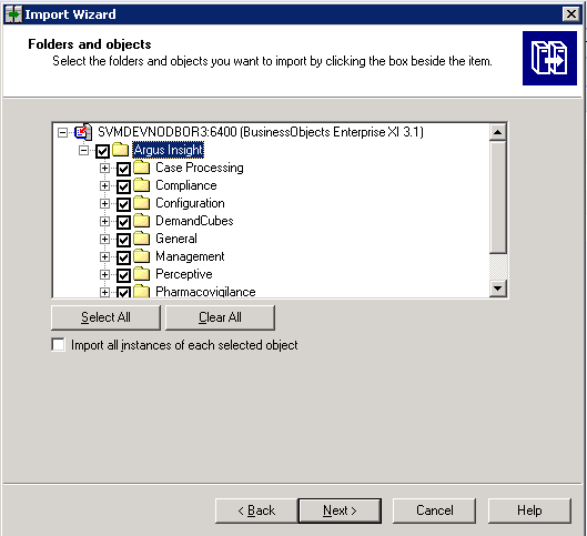
When the system opens the Folders and objects dialog box, select the folders and objects you want to import and click Next.
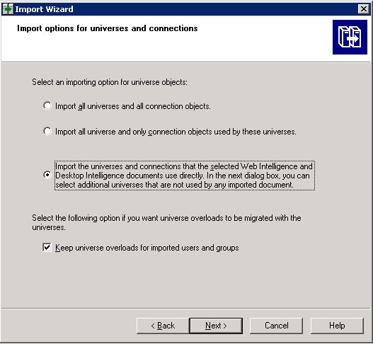
When the system opens the Import options for universes and connections dialog box, select the appropriate options as shown in the following illustration. Click Next.
The system opens the Universe folder and universes dialog box shown below.
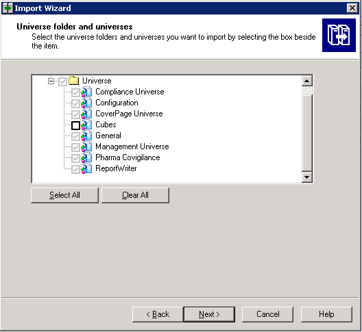
Click Clear All.
Check the root Universe folder. The following dialog is displayed.
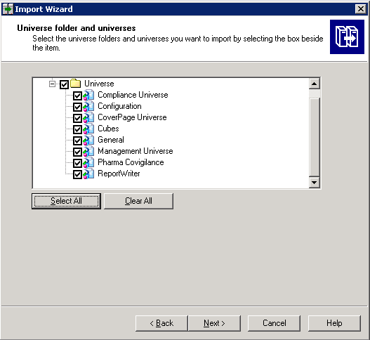
Click Next. The following dialog is displayed.
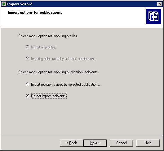
In the Import options for publications, select Do not import recipients and click Next.
When the system opens the A note on importing reports dialog box, click Next.
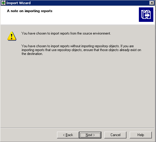
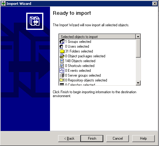
When the system opens the Ready to Import dialog box, click Finish.
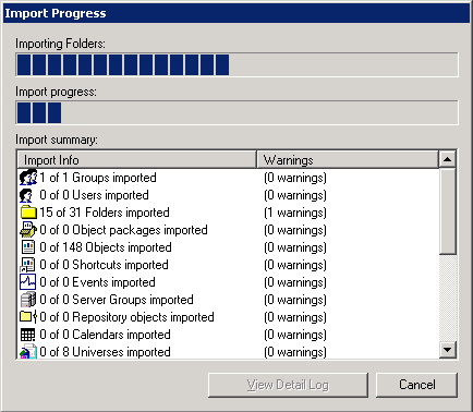
The system opens the Import Progress window.
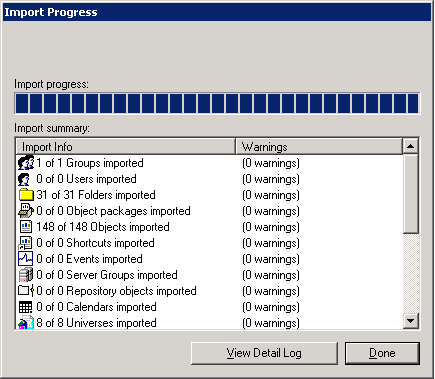
Click Done when the import is complete.
Before configuring the BOXI server, make sure the prerequisite software has been installed. For information about the prerequisite software, see Hardware and Software Requirements.
Use the following procedure to configure the BOXI server.
Open the Start->All Programs->BusinessObjects XI release 3.1->BusinessObjects Enterprise->BusinessObjects Enterprise Central Management Console.
Launch the Central Management Console.
When the system opens the Login page for Central Management Console, enter the Administrator password.
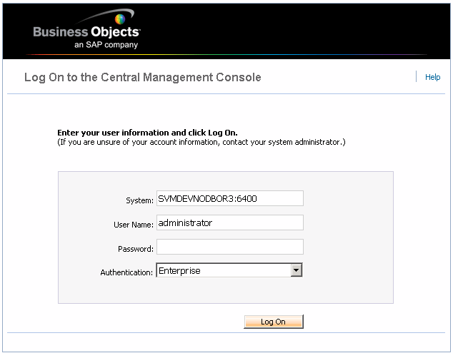
Click Log On.
If the BOXI server is different from the Argus Insight web server, do the following:
Copy the PRMART TNSEntry from Argus Insight Web Server.
If both the applications use same server and Oracle client, paste into BOXI Server TNSNAMES.ora.
There is no modification required in TNSNAMES.ora.
Trusted Authentication provides a transparent, single sign-on solution to the problem of how to integrate your Business Objects Enterprise authentication solution with third-party authentication solutions.
Once users log on to the system, they do not want to have to provide their password more than once in a session. In this scenario, Trusted Authentication allows applications that have established trust with the Central Management Server to log on users without their password.
To enable Trusted Authentication, you must configure both the Business Objects Server and the Argus Insight Web Server.
Use the following procedure to configure the server to use Trusted Authentication.
Log on to the Central Management Console (CMC) with administrative rights.
Click Authentication from the Home page.
Double-click on Enterprise.
Check the Trusted Authentication is enabled checkbox.
Create a shared secret for your users.
|
Note: The shared secret is used by the Argus Insight web server and the CMS to create a trusted authentication password. This password is used to establish trust. |
Enter a timeout value for your trusted authentication requests.
|
Note: The timeout value determines how long the CMS waits for the SessionMgr.Logon call from the Argus Insight application. Recommended Value is 0. |
Click Update.
When creating a valid configuration file on the Argus Insight web server, the following conditions apply to the configuration file:
The name of the file must be TrustedPrincipal.conf.
The file must be placed at this location: businessobjects_root/win32_x86.
The file must contain SharedSecret=secretPassword, where secretPassword is the trusted authentication password.
The file must be saved with UTF-8 encoding if it contains non-ASCII characters.
Either Tomcat or Websphere must be installed on the BOXI Server.
If Tomcat is not installed on the BOXI server, follow the steps provided below to configure WebSphere:
Verify that Websphere 6.0 is installed and working correctly.
This can be done by launching its default page, or administrative console in a web browser. Generally, this default path to Websphere is http://localhost:9060/ibm/console/.
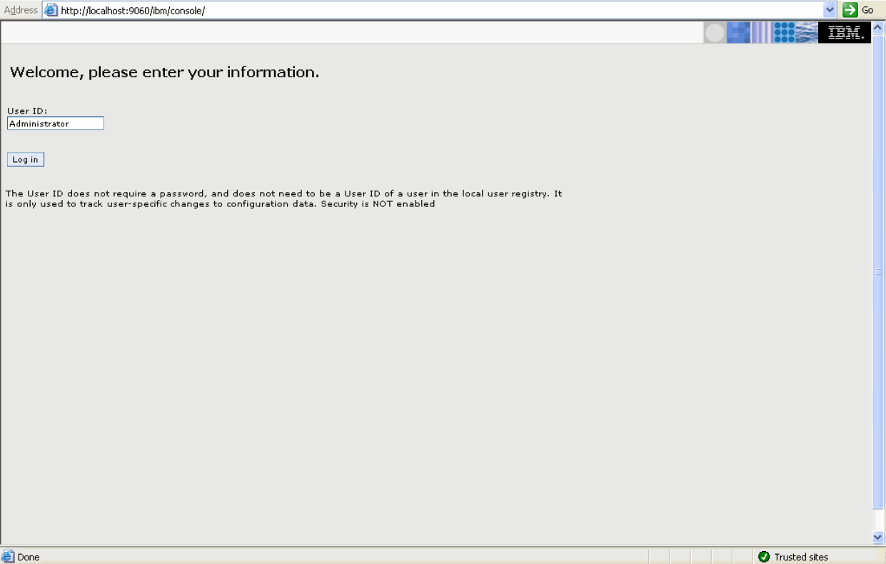
Also, verify and install the latest JVM on the Websphere Machine.
Install the BusinessObjects. While installing, please uncheck the Tomcat Server installation option.
Configure the WebSphere Server. For this you need to start the Websphere Administrative console.
Change the class path. Expand the Servers group in the navigation pane of administrative console.
Click Application Servers. Click Server1.
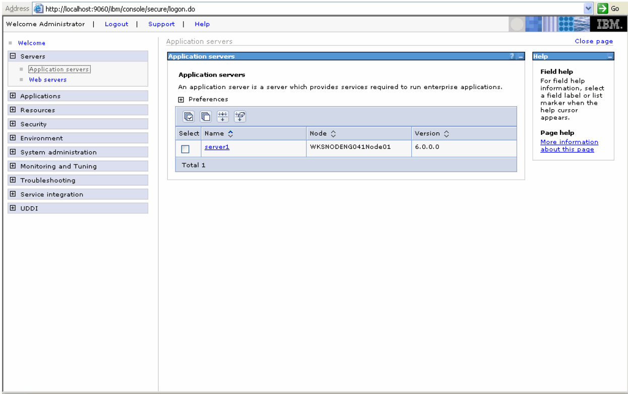
In the Configuration tab, under Server Infrastructure group, click Process Definition link.
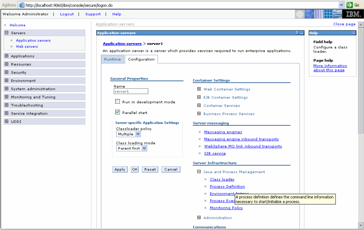
Click the Java Virtual Machines link in the Additional Properties section.
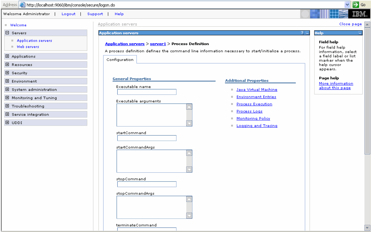
In the General Properties, in the Classpath field, write the path to the cewcanative.jar file. The following are the default locations for various files.

Save the changes to master configuration.
| Webcompadapter.war
Jsfadmin.war Desktop.war Admin.war Adhoc.war Styles.war Analysishelp.war Dswsbobje.war cewcanative.jar |
C:\Program Files\business objects\businessobjects enterprise 11.5\java\applications |
Change the Environmental Variable. Locate the win32_X86 folder in the BusinessObjects Enterprise install tree. The default location for this is c:\Program Files\Business Objects\BusinessObjects Enterprise 11.5\win32_X86.
Right-click on the My Computer icon on your desktop, click Properties. Then click the Advanced tab in the System Properties window.
Click Environment Variables.
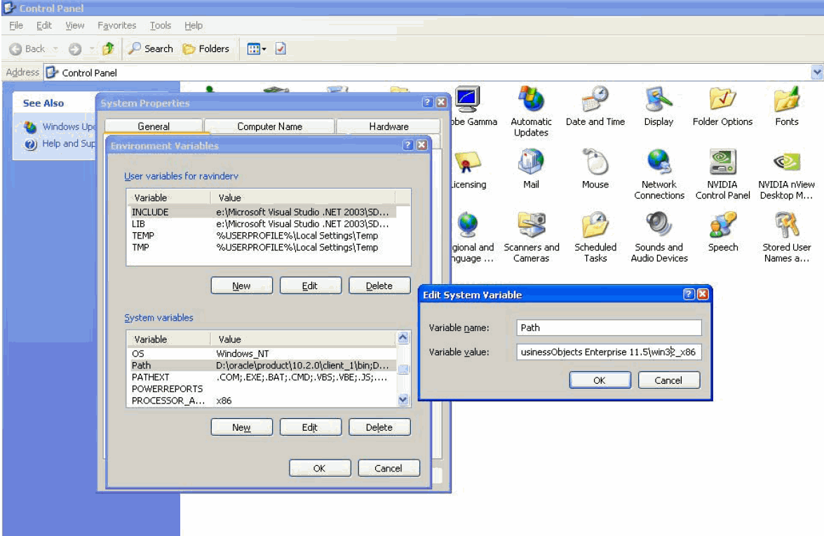
Scroll down until you find the Path system variable. Double click on it.
Get to the end of the Variable Value field. Add a semicolon (;) and then add the location of win32_X86 folder.
Click OK twice.
Use the following procedure to deploy the WebSphere Server
Open the Administrative console.
Expand Applications, and then click Install New Application.
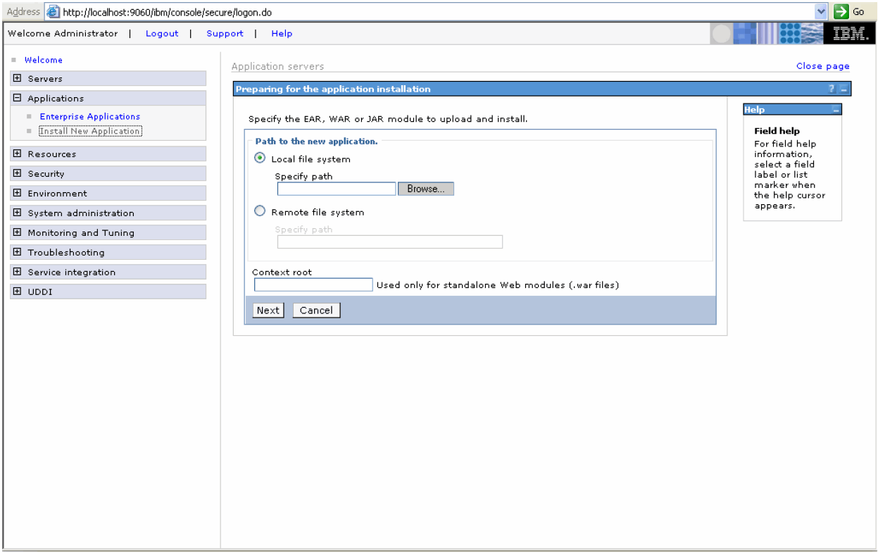
Click Browse and find the location of the desktop.war file. See the table shown above for the file locations.
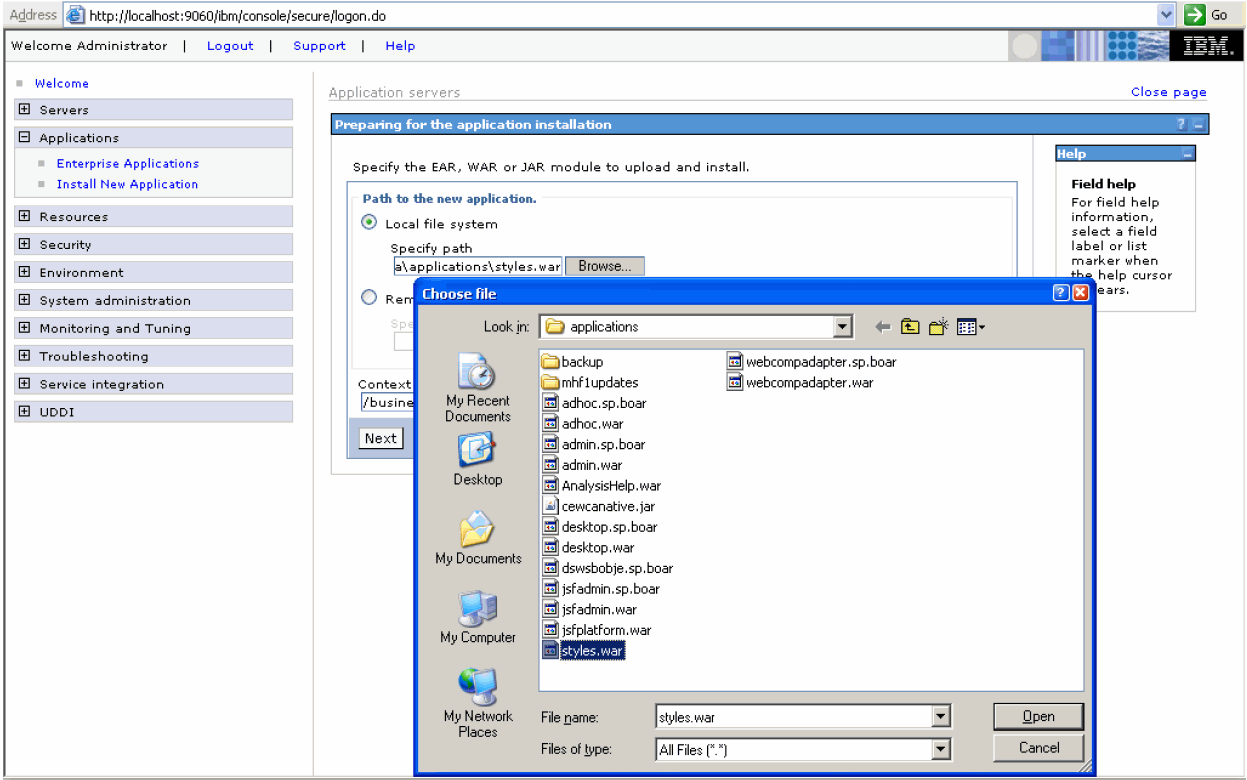
Type the context root for the war file in the Context Root field. Consult the following table for the order and the context root of various files to be deployed.
| War File | Context Root |
| Desktop.war | /businessobjects/enterprise115/desktoplaunch/businessobjects |
| Webcompadapter.war | /businessobjects |
| Jsfadmin.war | /jsfadmin |
| Admin.war | /businessobjects/enterprise115/adminlaunch |
| Adhoc.war | /businessobjects/enterprise115/Adhoc |
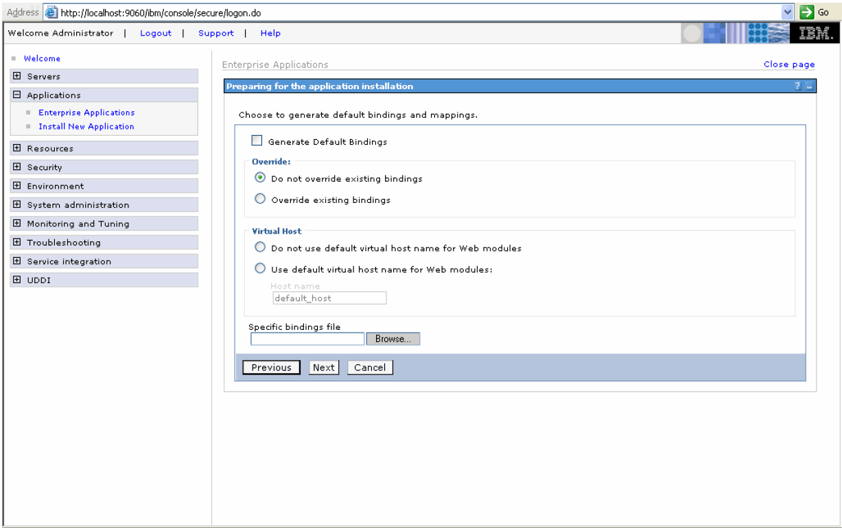
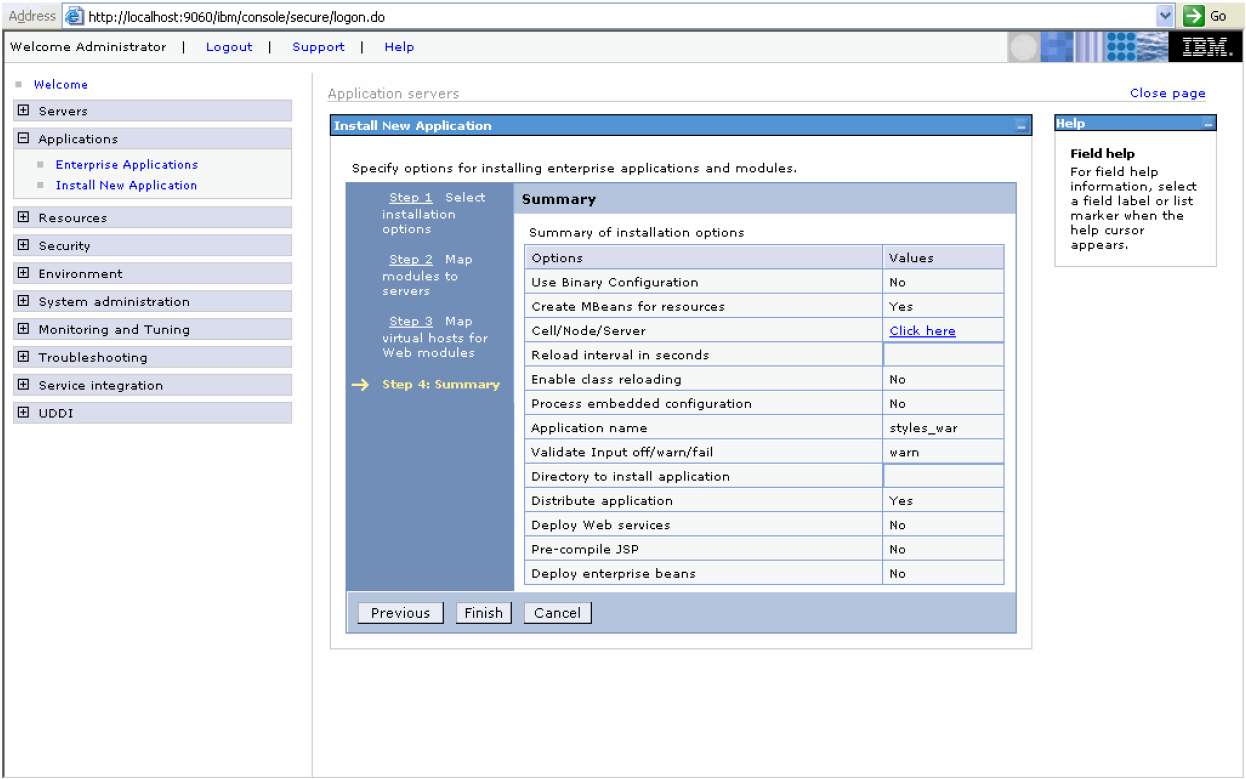
Click Next.
Accept the defaults on each page and click Next until you get to Step 2: Map modules to servers.
Select the Application Server (i.e. server1) and click Next.

Select the Web Module in the list and click Next.

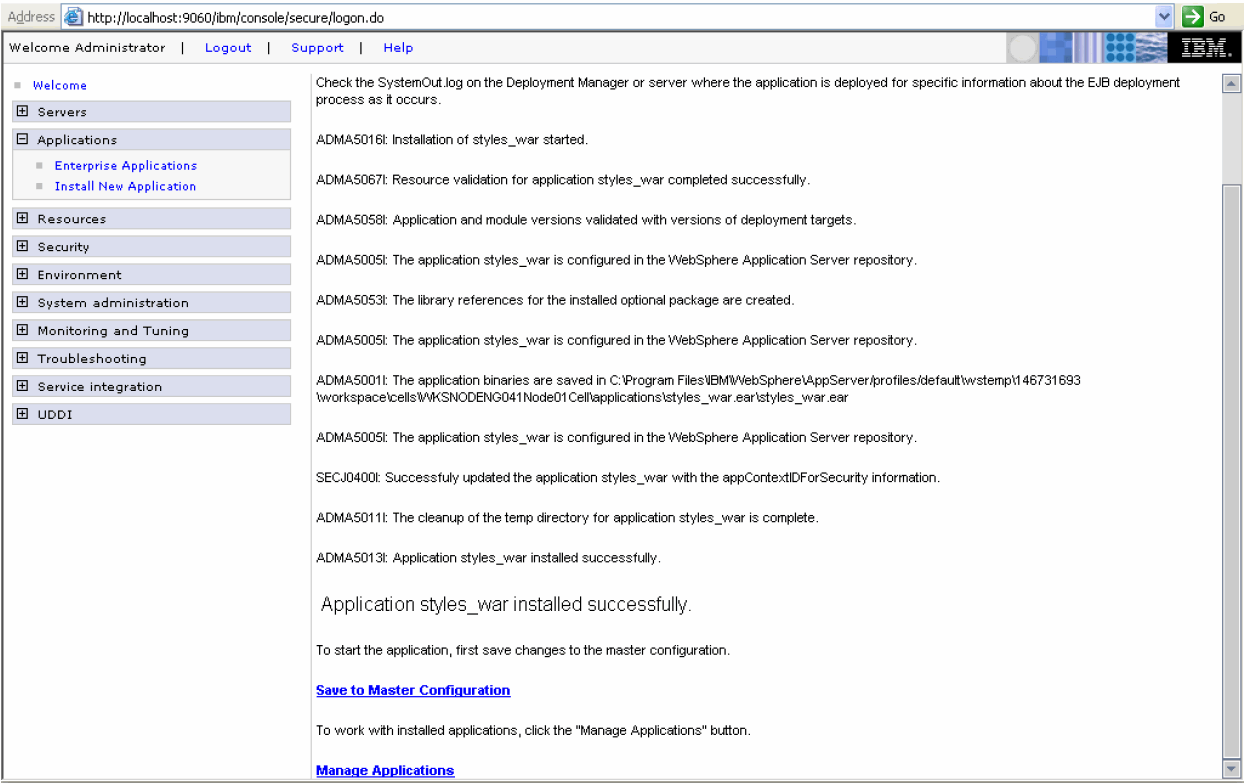
Click Finish. You will receive messages when the process is complete.
Save the changes to the Master configuration.
Repeat the process for all above files. Remember to deploy these files in the order they are mentioned in the table shown above, otherwise, the integration will fail as these files have dependencies on each other.
Verify if we have integrated the BOXI with Websphere successfully or not.
For this, open a browser window.
Enter the URL for the desktop launchpad in the browser using the format http://[hostname]:[port number]/businessobjects/enterprise115/desktoplaunch. For example:
http://localhost:9080/businessobjects/enterprise115/desktoplaunch
|
Note: You cannot use the shortcuts in the BusinessObject Enterprise program group to access the BusinessObjects Enterprise launchpads deployed on your Websphere Server. To access them, you must include the port number of the Websphere Server in your URL. |
Use the following procedure to change the connection string.
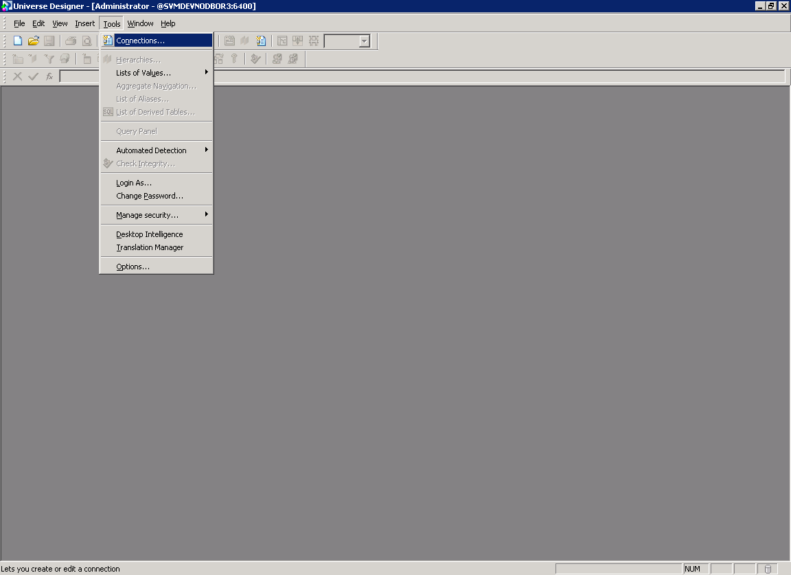
Open Business Objects Designer. Go to Tools > Connections.
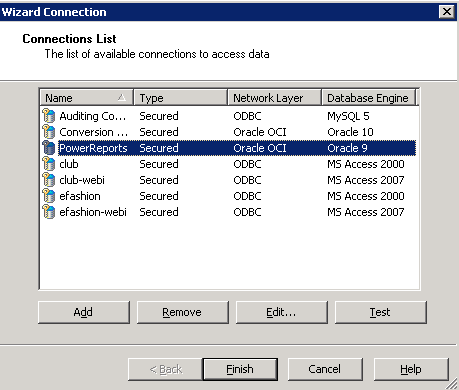
When the system opens the Wizard Connection dialog box, select PowerReports connection and click Edit.
You might get the following warning. Click Yes.

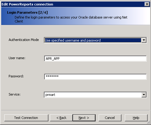
Enter the User name and password for Argus Insight database Read-Only user / APR_APP user in the Edit PowerReports connection dialog. The Read-Only user is created during schema creation. For example, APR_MART_DB_LINK_USER. Click Next.
|
Note: APR_APP user has rights to update many of the MART tables. If user wants to use Read-Only account for BOXI connection they can use APR_MART_DB_LINK_USER account, but Case Series Freezing will not be supported in Reports and ReportWriter with the use of Read-Only account. |
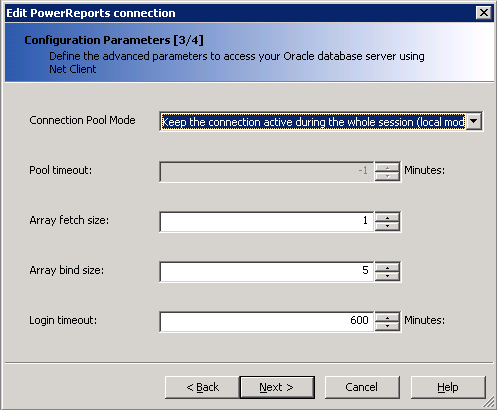
When the system opens the Advance Parameters dialog box, click Next.
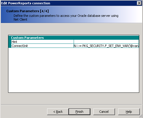
When the system opens the Custom Parameters dialog box, click Finish.
When the system opens the Edit PowerReports connection dialog box from Wizaed Connections, click Test Connection. You get the following dialog.
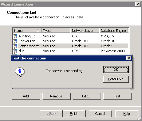
Click OK and Finish to exit from the Business Objects Designer.
Open the Start ->All Programs -> BusinessObjects XI release 3.1 -> BusinessObjects Enterprise ->BusinessObjects Enterprise Central Management Console.
Click Launch the Central Management Console.
In the Password field enter password.
Click Log On.

Click on Users and Groups.
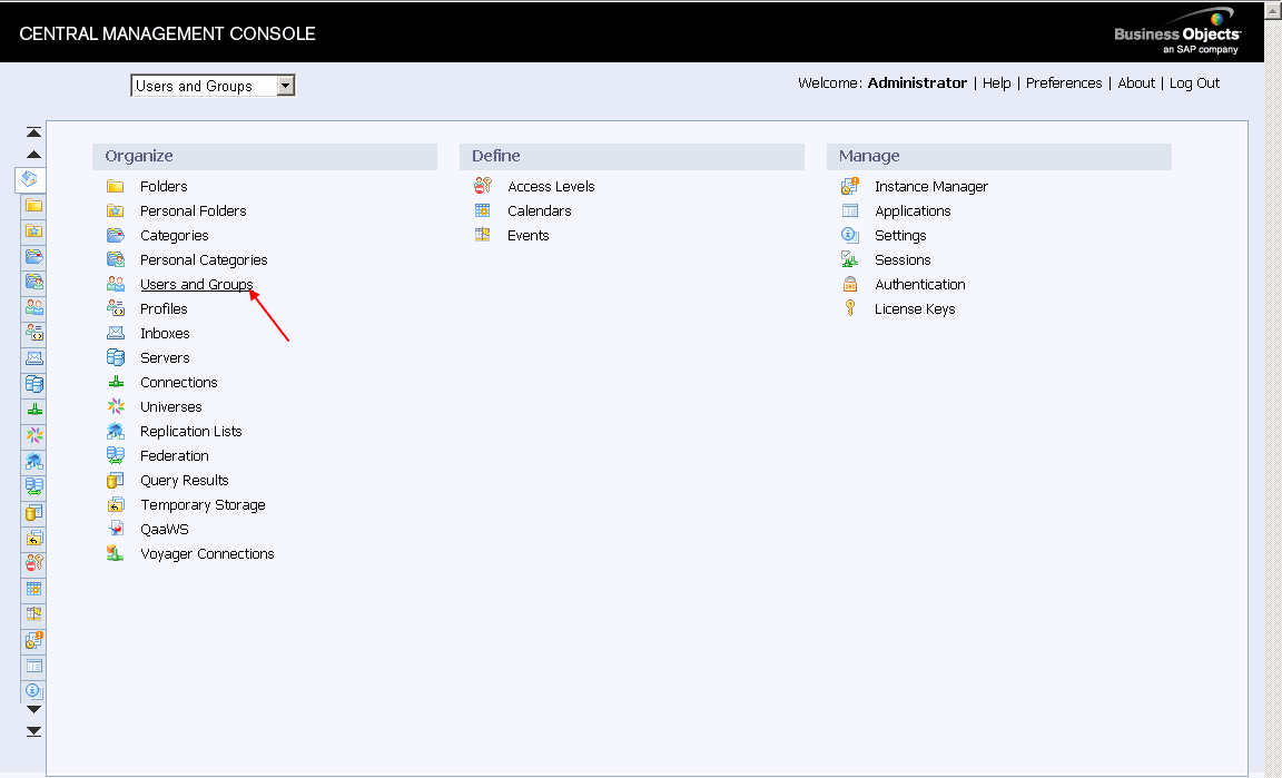
Click PRGroup.
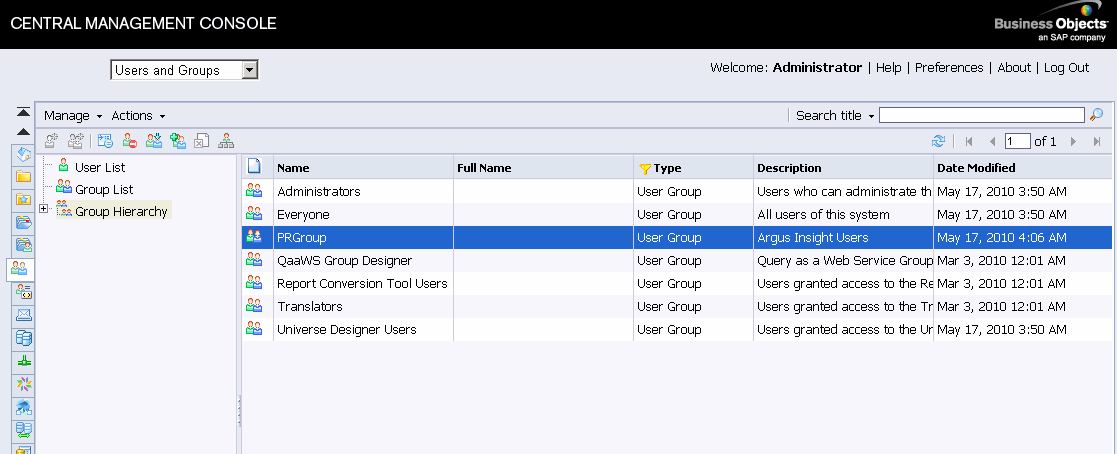
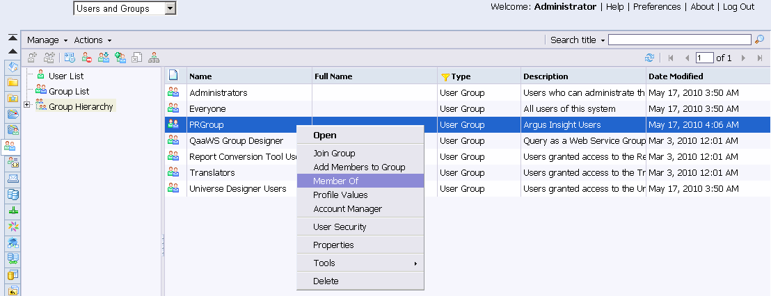
Right-click PRGroup and click Member of.
The following screen appears. Click Join Group.
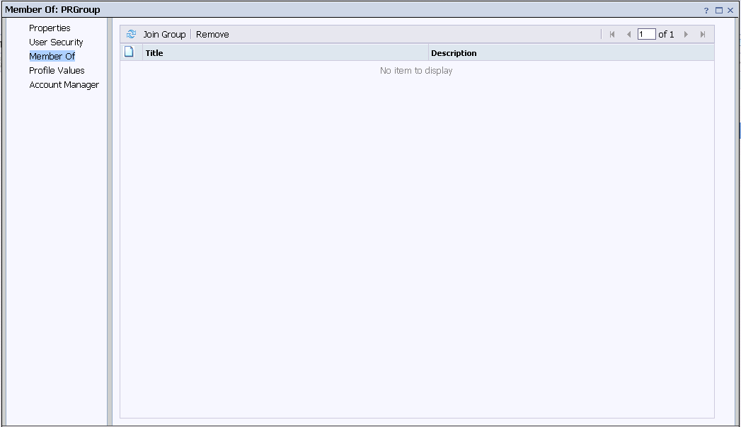
Move Administrators, Everyone, and Universe Designer group from Available groups to Destination Groups.
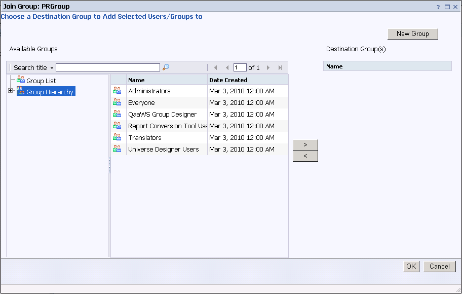
Click OK. The following screen is displayed.

Click Close.
Use the following procedure to configure Argus Insight Folder rights.
Open the Start ->All Programs -> BusinessObjects XI release 3.1 -> BusinessObjects Enterprise ->BusinessObjects Enterprise Central Management Console.
Launch the Central Management Console.
Enter your administrator user name and password.
Click Log On.

The system opens the Central Management Console.
Click Folders.

Right-click Argus Insight and click User Security.

Select Administrators and click Assign Security.

The following screen is displayed.
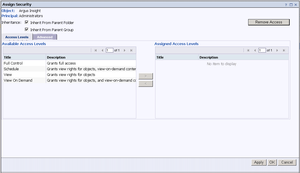
Uncheck the "Inherit from Parent Folder" and "Inherit from Parent Group" checkboxes and assign the Full Control Access as shown below.
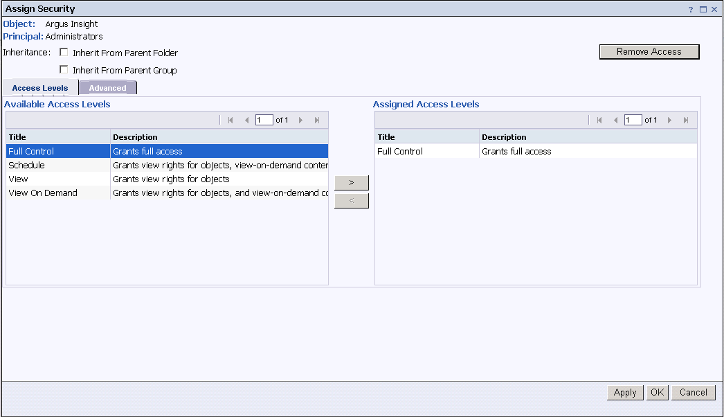
Click the Advanced tab in the Assign Security screen and click Add/Remove Rights.
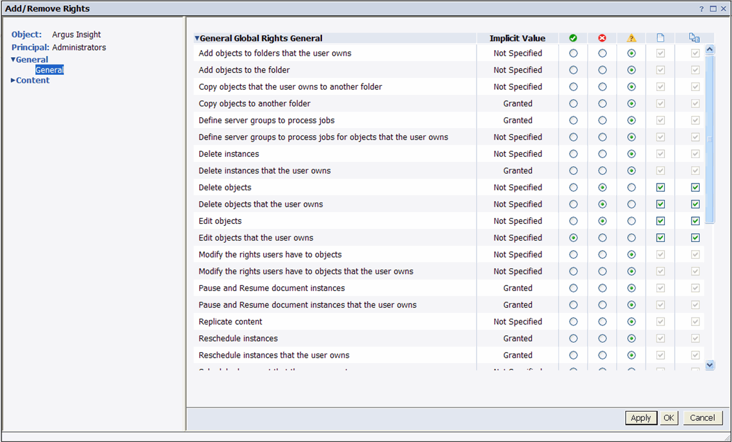
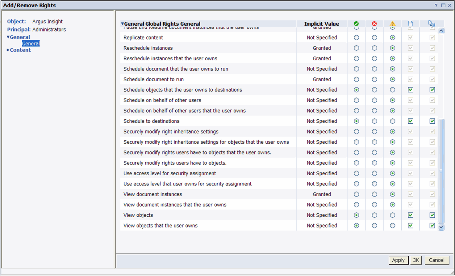
Click OK.
The following screen is displayed.
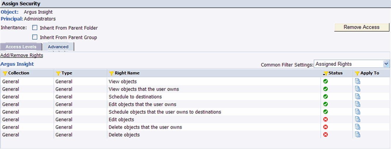
Click OK. The following screen is displayed.

Select Everyone and click Assign Security.
The following screen is displayed.
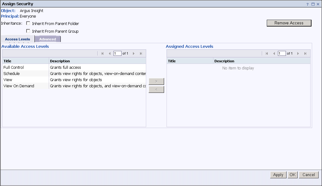
Assign the Schedule and View Control Access, as shown below.
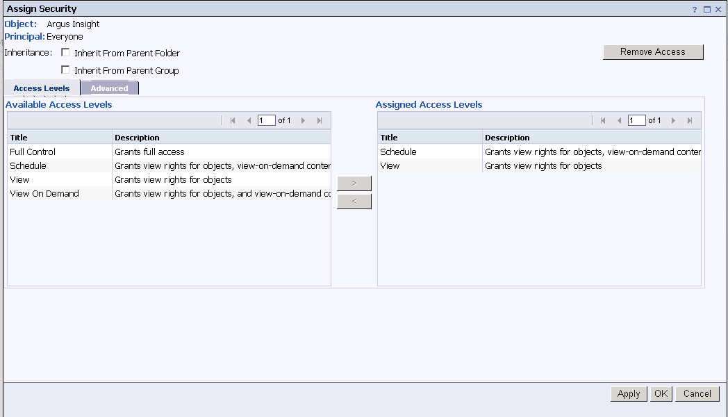
Click OK. The following screen is displayed.

Click Add Principals. The following screen is displayed.
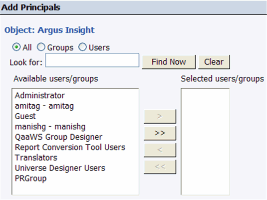
Select PRGroup from Available users/groups and click > to move it to Selected users/groups. The following screen is displayed.
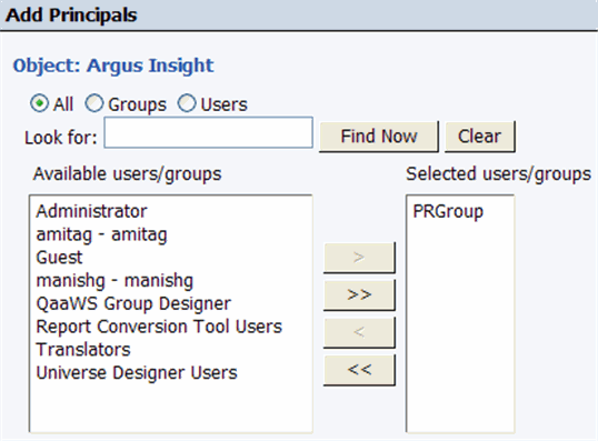
Click Add and Assign Security. The following screen is displayed.
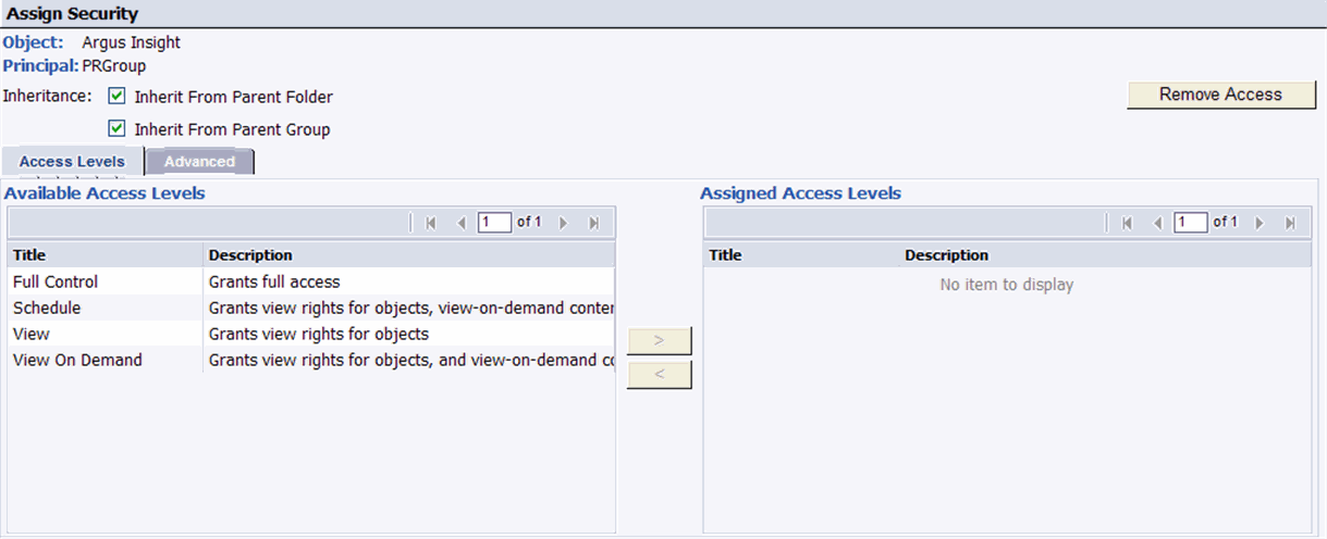
Select Full Control and click > to move it under Assigned Access Levels. The following screen is displayed.
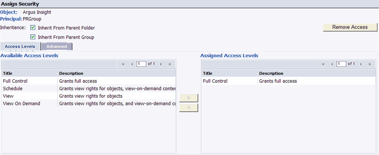
Click OK. The following screen is displayed.

Click Close.
Use the following procedure to configure rights for the BusinessObjects Applications.
Open the Start ->All Programs -> BusinessObjects XI release 3.1 -> BusinessObjects Enterprise ->BusinessObjects Enterprise Central Management Console.
Launch the Central Management Console.
Enter your administrator user name and password.
Click Log On.

The Home page appears, as shown below. Click Applications.
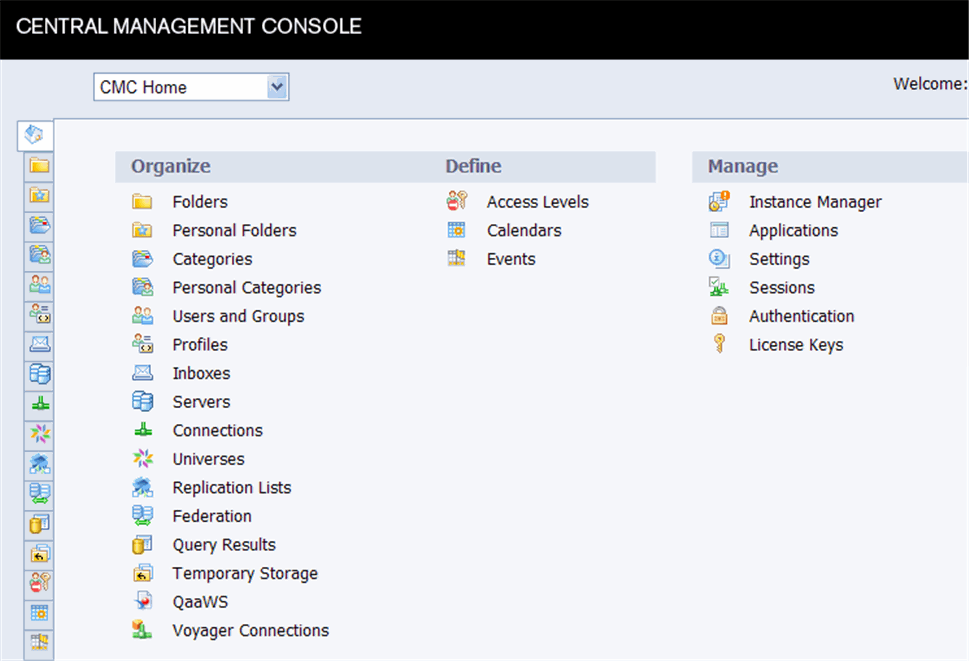
The following screen is displayed.
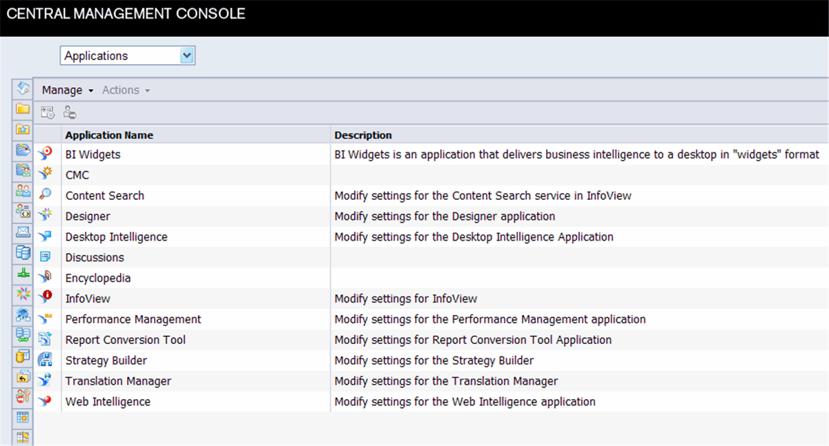
Right-click Web Intelligence and select User Security. The following screen is displayed.

Click Add Principals. The following screen is displayed.
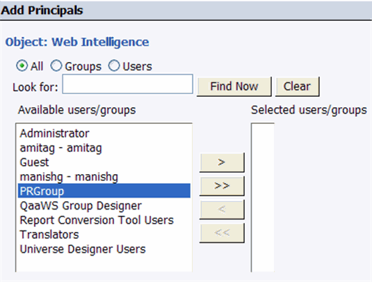
Select PRGroup and click > to move it under Selected users/groups.
Click Add and Assign Security. The following screen is displayed.
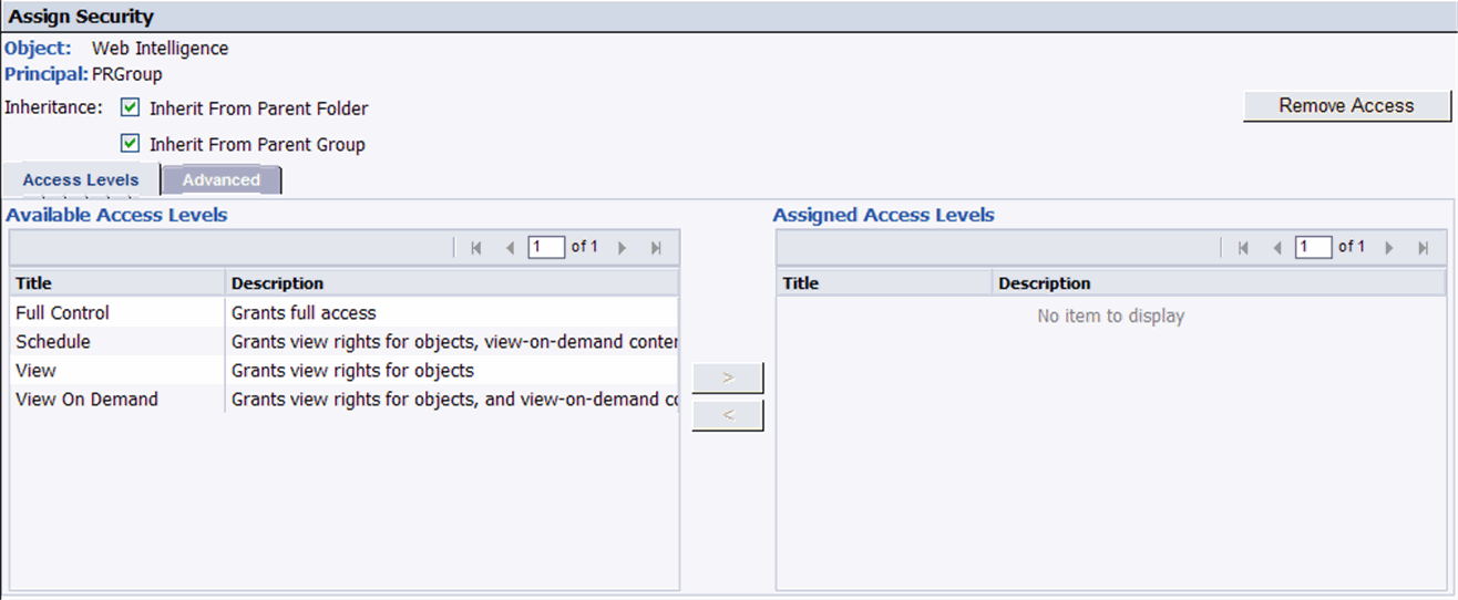
Select Full Control and click > to move it under Assigned Access Levels. The following screen is displayed.
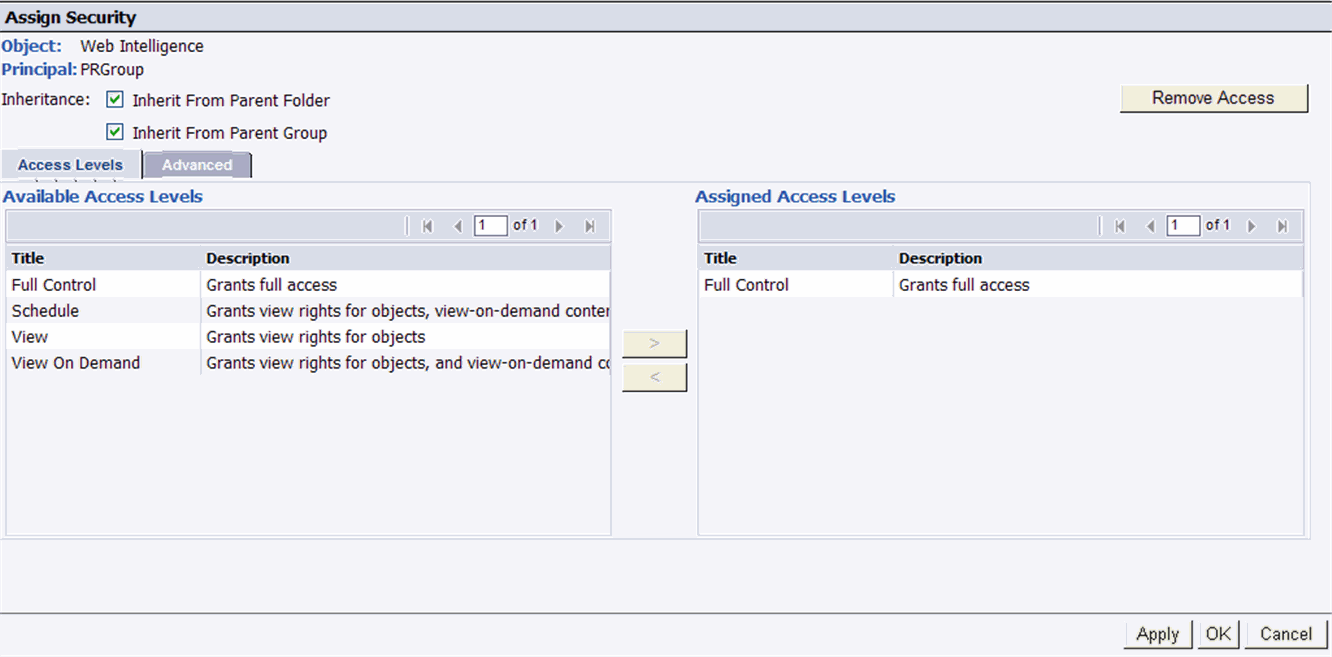
Click OK.
Follow the procedure mentioned in steps 3 - 9 to configure rights for the Desktop Intelligence and Designer applications for BusinessObjects.
This section contains instructions for configuring the Argus Insight Web Server.
IMPORTANT! Follow the installation procedures in the order in which they appear in this section.
This section contains the procedure for scheduling batch generation using Windows Task Manager. You must perform this procedure for each of the six Cubes.
Select Start > Settings > Control Panel->Scheduled Tasks.
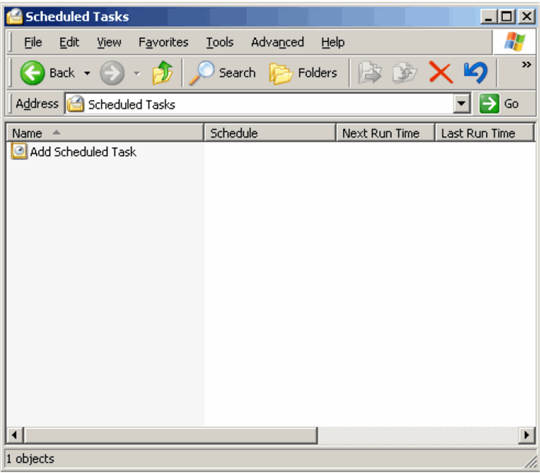
When the system opens the Scheduled Tasks dialog box, double-click the Add a Scheduled Task item.
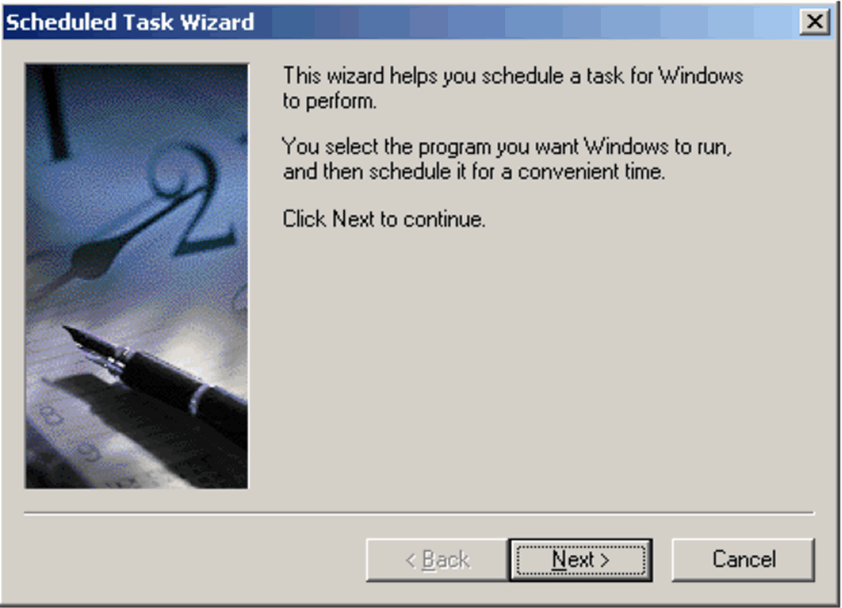
When the system opens the Scheduled Task Wizard dialog box, click Next.
When the system opens the next dialog box, click Browse.
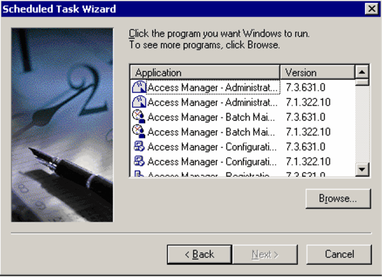
Navigate to the following location:<Argus Insight Installation Folder>\ArgusInsight\CubeGenThis is the path of the folder where the Argus Insight application is installed on the system drive. For example D:\Oracle\ArgusInsight\CubeGen.
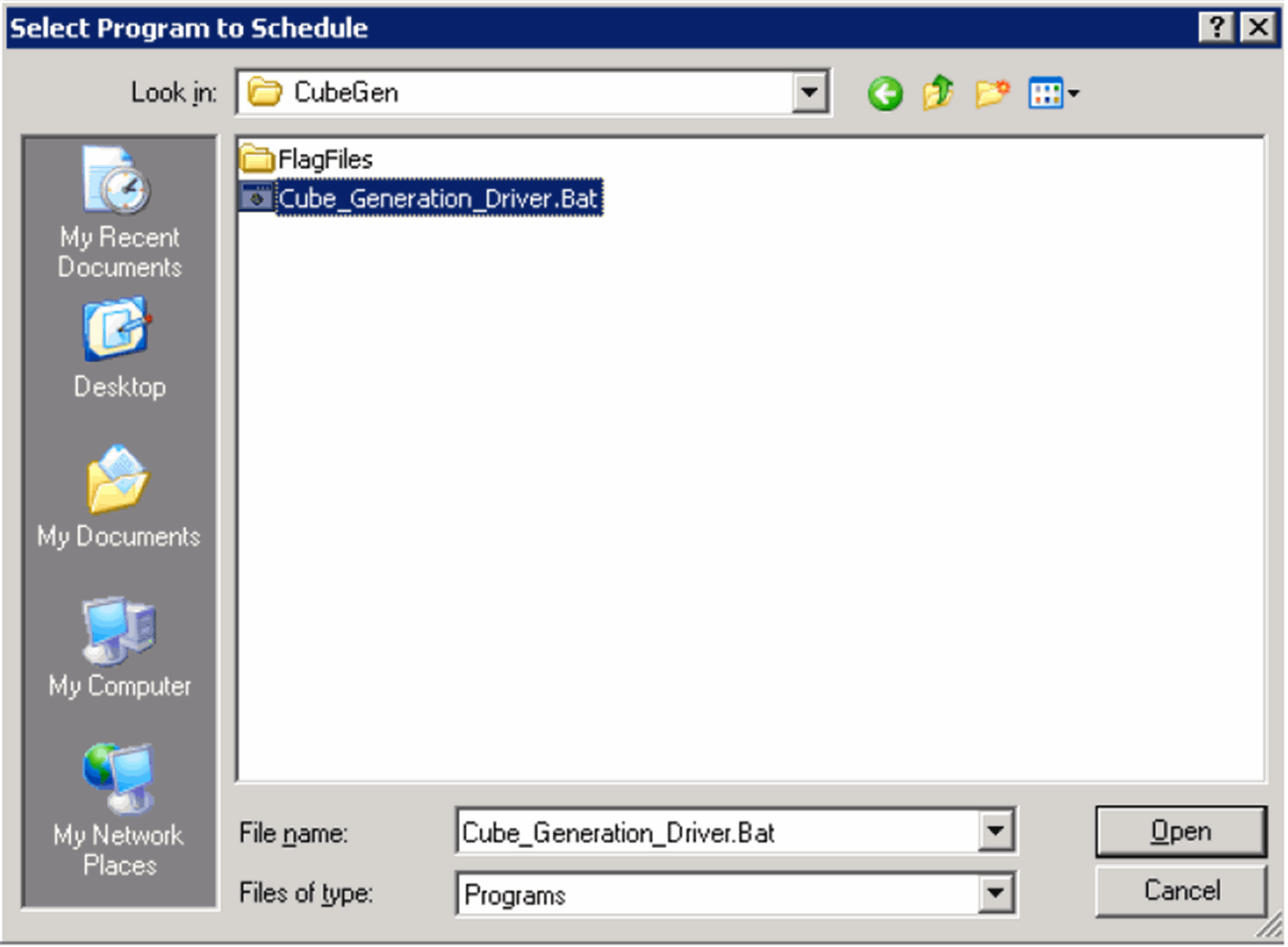
When the system opens the Select Program to Schedule dialog box, select the Cube_Generation_Driver.bat file. Click Open.
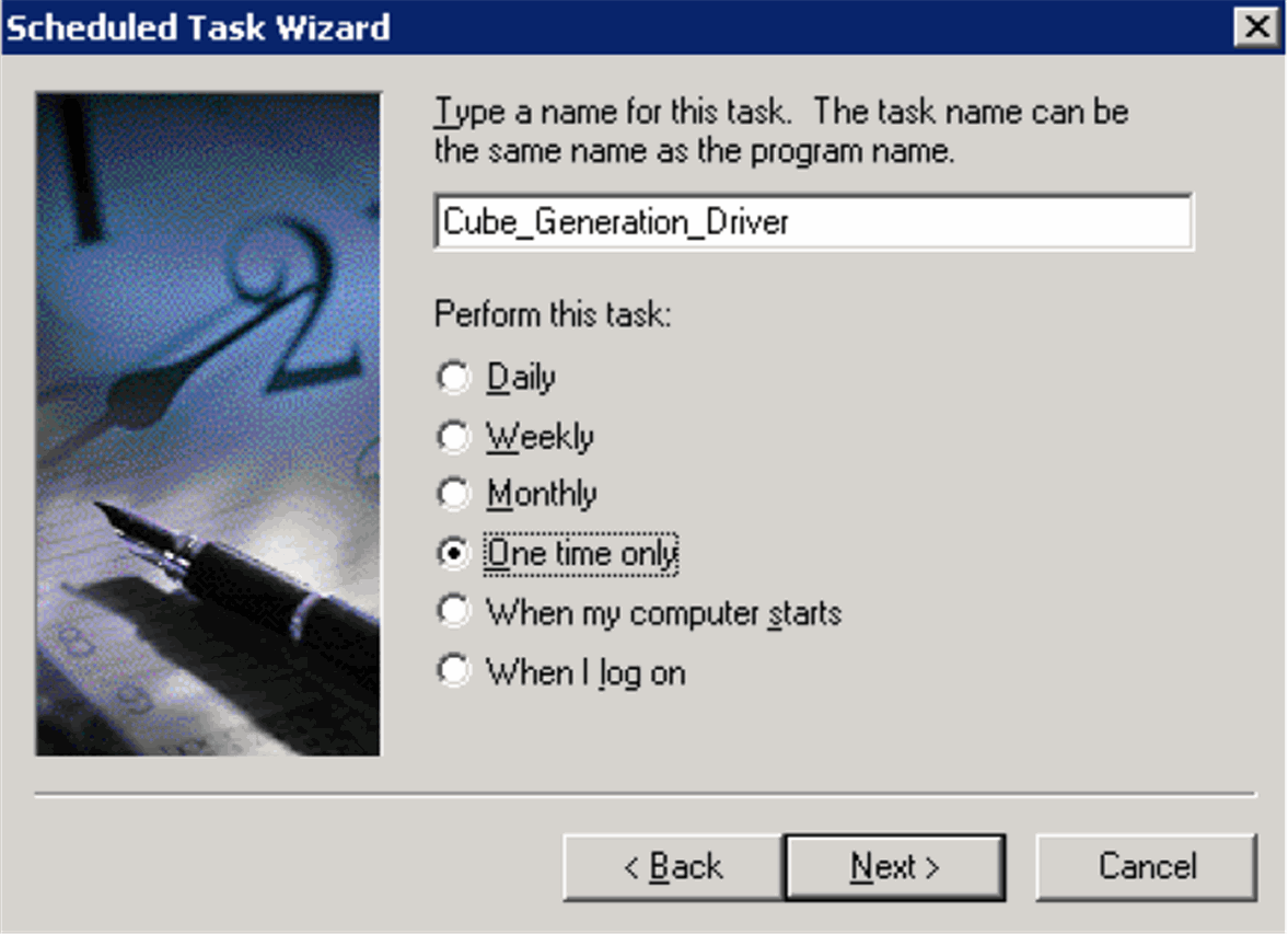
When the system opens the following dialog box, type Cube Generate 1 in the task name field.
Enter the task name in the format Cube Generate <Cube ID>.
Use the Perform this task option button group to set the frequency of the task, as appropriate.
Click Next.
The Cube IDs are listed in the following table.
| Cube Name | Cube ID |
| PV Clinical | 1 |
| PV General | 2 |
| PV Interaction | 3 |
| PV Detail | 4 |
| Reporting Compliance | 5 |
| Workflow | 6 |
In the date dialog box, do the following:
Set the Start time and Start date.
Click Next.

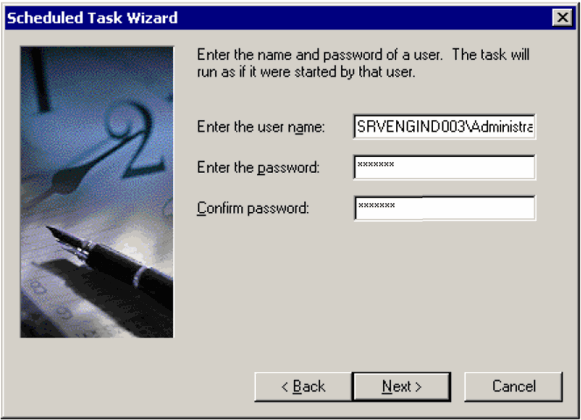
Enter the user name and password of the user authorized to run this task and click Next.
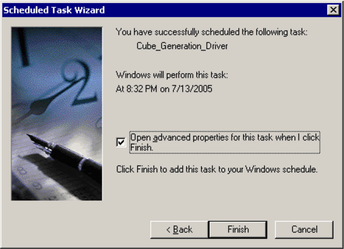
Select the Open advanced properties for this task when I click finish checkbox. Click Finish.
When the system opens the dialog box for setting advanced properties, do the following:
In the Run text box within the Task tab, enter the run-time parameter for this task in the following format:
<Argus Insight Installation Folder>\Argus Insight\Cube_Generation_Driver.bat" <Cube ID>
where CubeID is the ID of the Cube for which you are scheduling the batch generation.
Include the double quotation marks (" ") when entering the runtime parameter.
The following table lists the Cube ID for each cube and provides examples of the run-time parameter to be entered.
| Cube Name | CubeID | Example Run-Time Parameter |
|---|---|---|
| PV Clinical | 1 | "D:\Oracle\ArgusInsight\CubeGen\Cube_Generation_Driver.bat" 1 |
| PV General | 2 | "D:\Oracle\ArgusInsight\CubeGen\Cube_Generation_Driver.bat" 2 |
| PV Interaction | 3 | "D:\Oracle\ArgusInsight\CubeGen\Cube_Generation_Driver.bat" 3 |
| PV Detail | 4 | "D:\Oracle\ArgusInsight\CubeGen\Cube_Generation_Driver.bat" 4 |
| Reporting Compliance | 5 | "D:\Oracle\ArgusInsight\CubeGen\Cube_Generation_Driver.bat" 5 |
| Workflow | 6 | "D:\Oracle\ArgusInsight\CubeGen\Cube_Generation_Driver.bat" 6 |
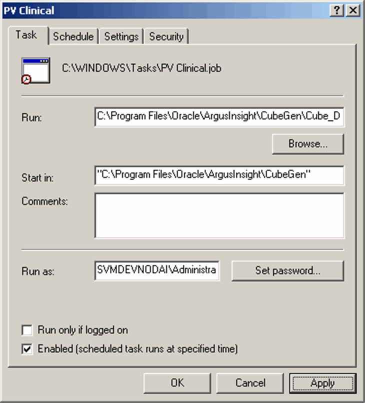
Click Set Password.
Enter the password for the ReportNet Server admin user. Click OK
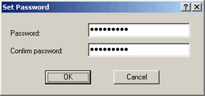
Select the Schedule tab and set the appropriate schedule options.
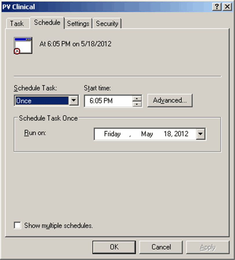
Select the Settings tab and set the options as shown in the following illustration.

Select the Security tab.
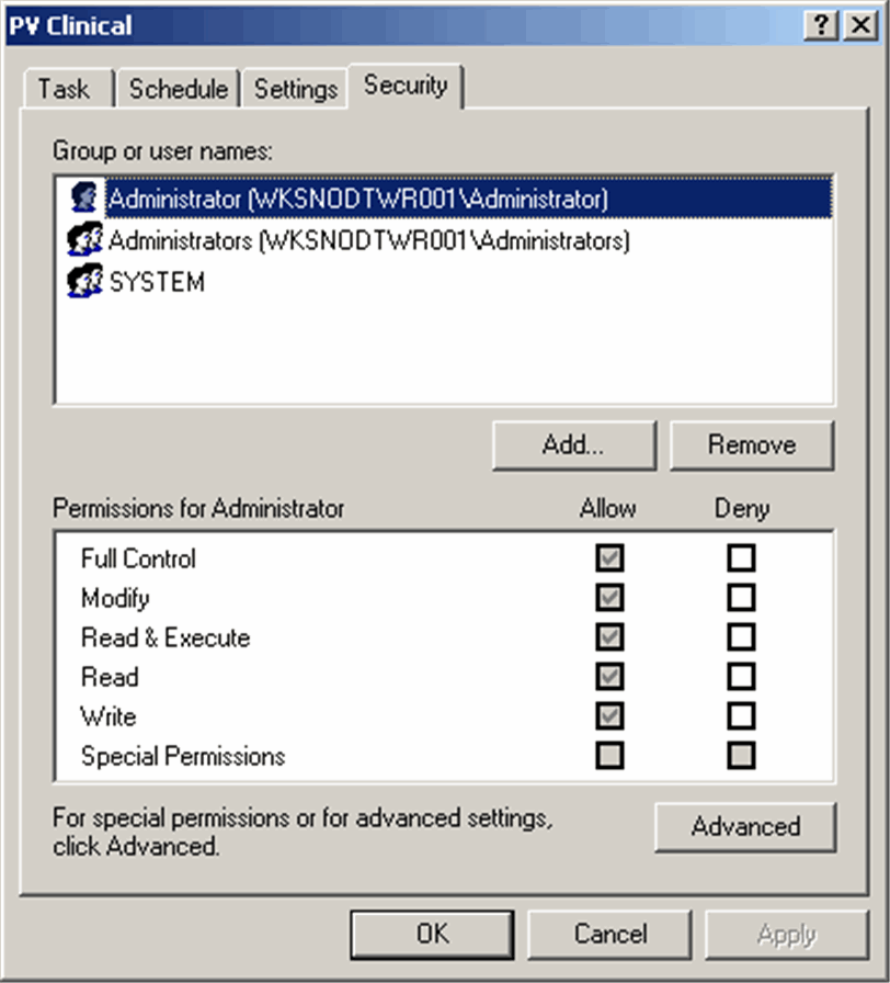
Verify that the user has full permissions assigned. Click OK.
The system creates the new scheduled task Cube Generation.
Repeat the above steps to schedule batch generation for the remaining cubes.
These are required settings because PwReports.exe file is responsible for LDAP authentication along with CIOMS and MedWatch reports.
Go to Start -> Run and type dcomcnfg and press Enter.
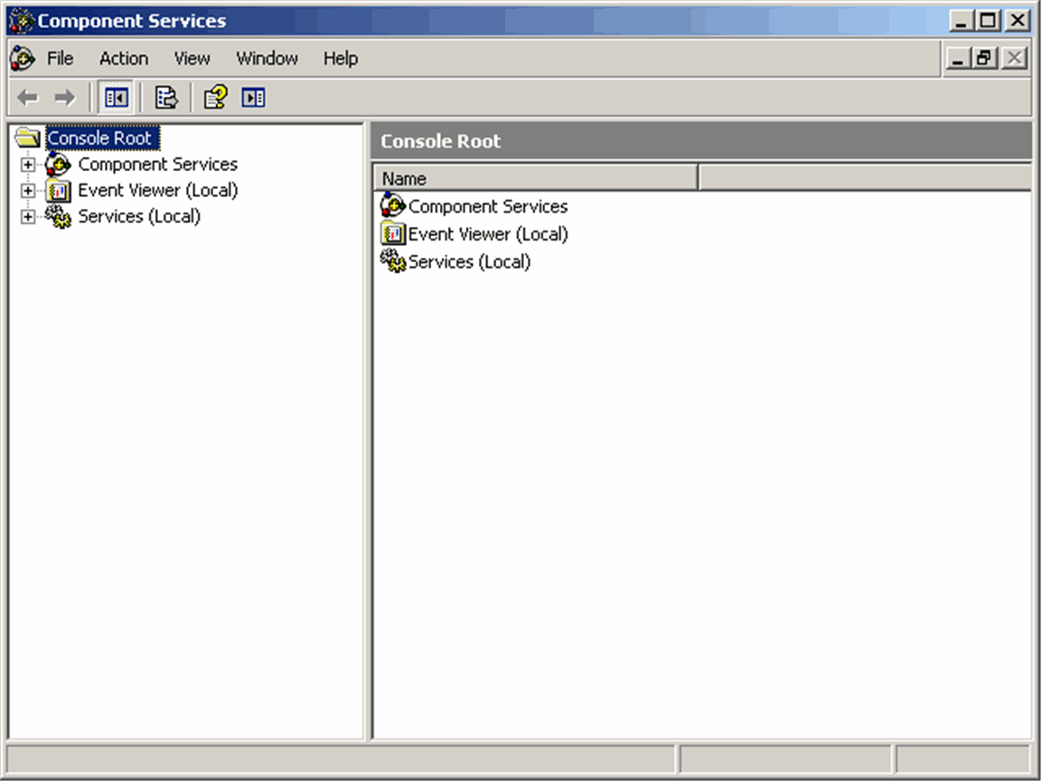
In the tree under Console root->Component Services->Computer->My Computer->DCOM Config.
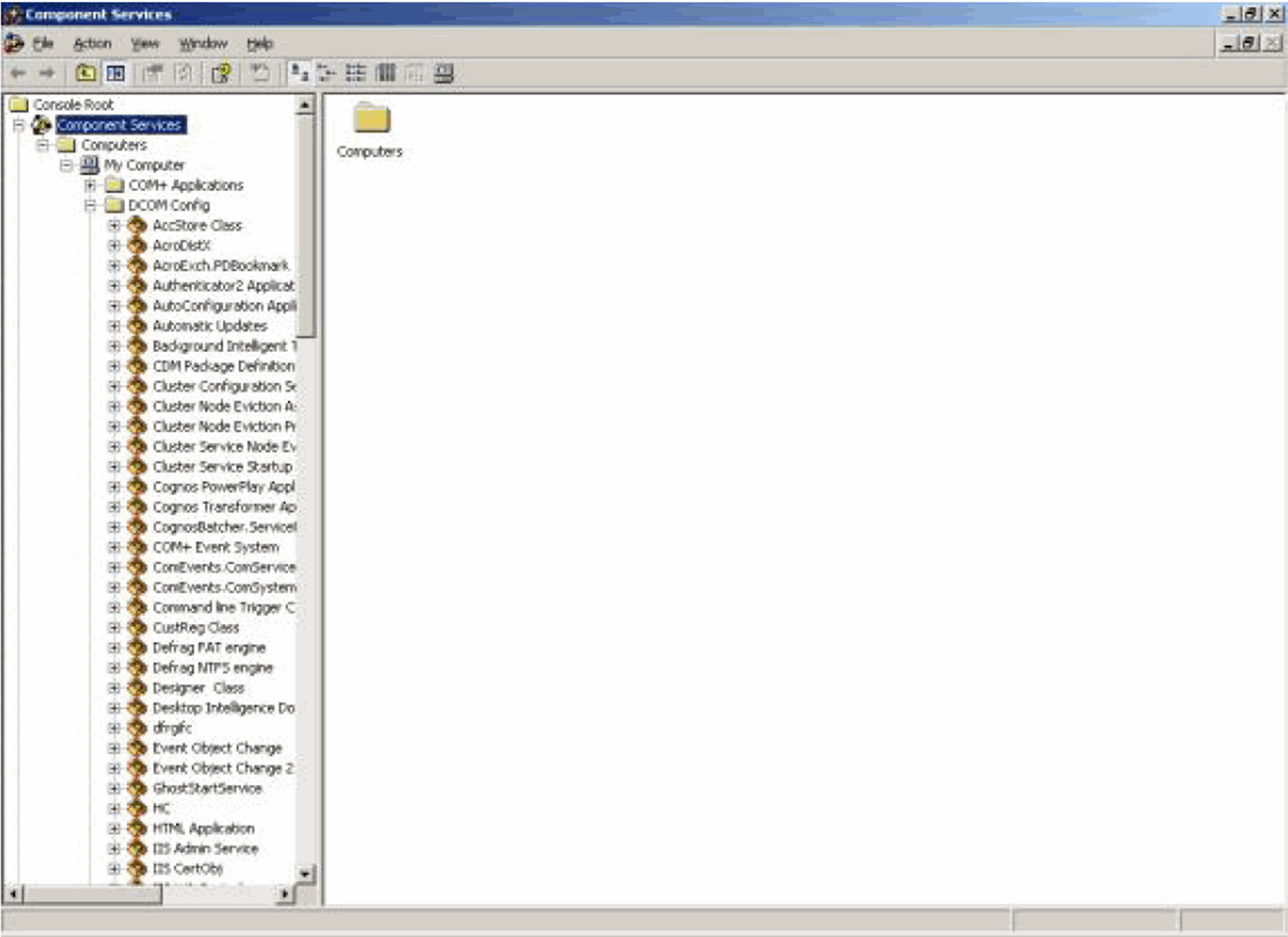
Right click on the PwReports in the list and click Properties.
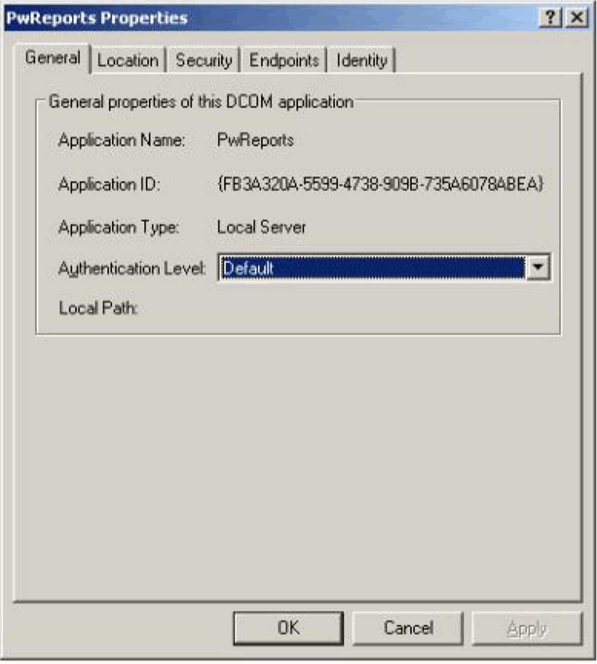
Click on the Security tab.
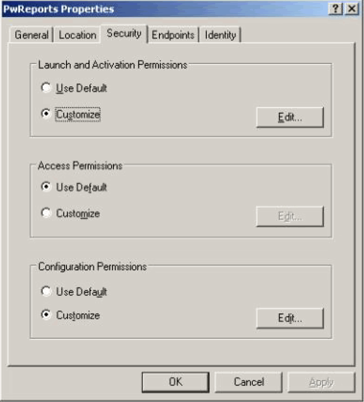
In the Launch and Activation Permissions Mark Customize and click Edit...
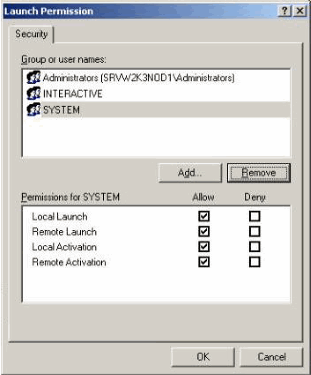
Click Add…
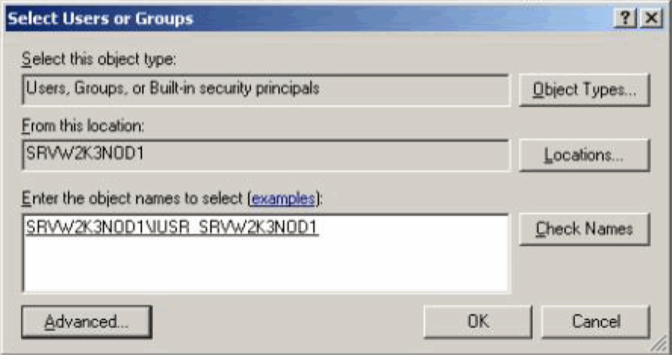
Under Enter the object names to select (examples), add <machine_name>\IUSR_<machine_name> and click OK.
|
Note: If you are using a Windows 2008 Server, add <machine_name>\IUSR and click OK. |
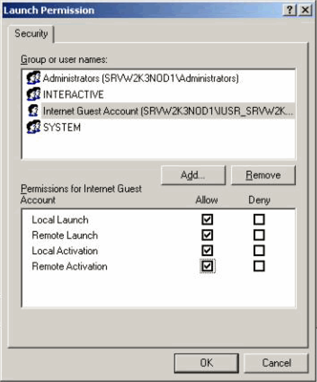
Highlight the newly created Internet Guest Account.
Check all the permissions.
Click OK.
Exit the Component Services program.
Use the following procedure to configure the IIS file download limit for Windows 2003.
Stop the IIS service. Go to Start -> Run. Type iisreset -stop to stop the IIS service.
Go to C:\Windows\system32\inetsrv\metabase.xml file . By default, this file has this entry: AspBufferingLimit = "4194304" This limits the download size to 4,194,304 bytes (4 MB).
Change this size to a large value (such as 200000000 for 200 MB) to allow your Windows 2003 server to send large downloads.
Start the IIS service. Go to Start -> Run. Type iisreset -start to start the IIS service.
Use the following procedure to configure the IIS file download limit for Windows 2008:
Go to the Internet Information Services (IIS) Manager.
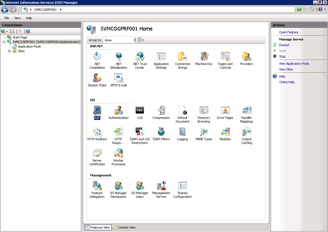
Double-click ASP in the right pane. The following page appears:
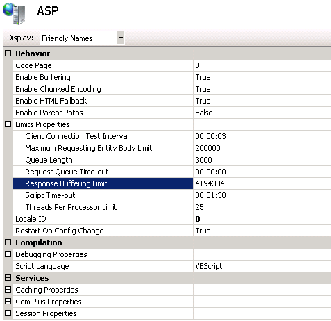
Expand Limit Properties and change the Response Buffering Limit from its default value of 4 MB to a large value such as 200000000 (200 MB).
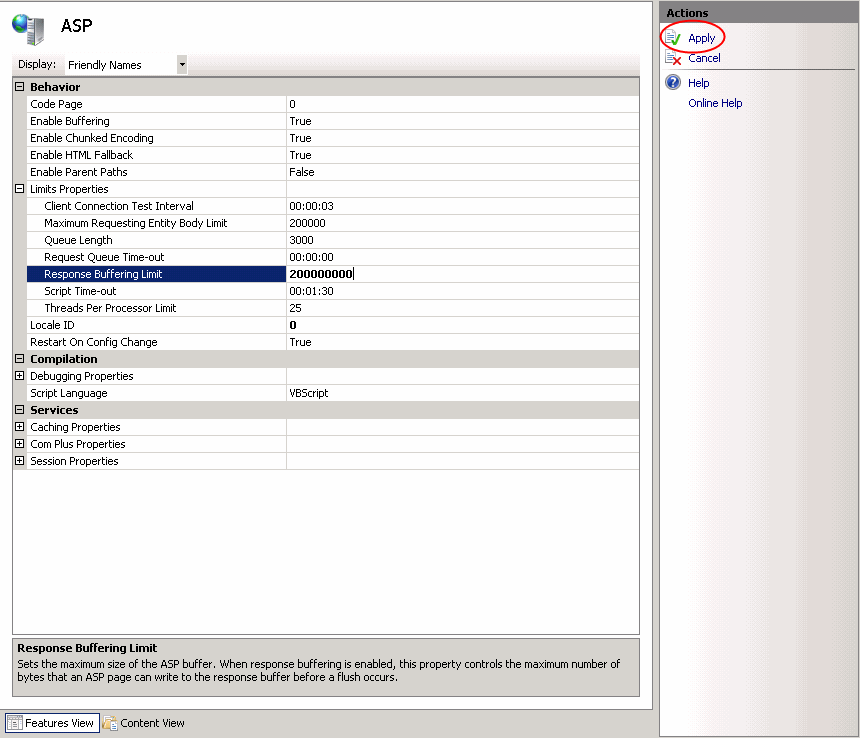
Click Apply to save the changed value.
Restart the IIS service. Go to Start -> Run. Type iisreset to restart the IIS service.
Configuring the ASPMaxRequestEntityAllowed Value (Optional Setting)
This setting is required only if end-users are using custom SQLs in advanced conditions, with more than 70,000 characters. If any AJAX error appears while saving the Custom SQLs of these many characters, update the ASPMaxRequestEntityAllowed value of the MetaBase.xml file. This ensures that the ASP can post that much data onto the server. There are two ways of updating this value: 1. By updating the MetaBase.xml: a) Stop the IIS. Use "iisreset /stop" at command prompt b) Go to \WINDOWS\system32\inetsrv c) Open the MetaBase.xml file in notepad d) Edit the Value of ASPMaxRequestEntityAllowed and set it to 500000 e) Save the file and restart the IIS. Use "iisreset /start" at command prompt. 2. By using the DOS Prompt: a) At a command prompt, type the following command, and then press ENTER: cd drive:\inetpub\adminscripts Note that in this command to change folders, the drive is only a placeholder for the hard disk where IIS is installed. b) On the command prompt, type the following command, and press ENTER: cscript adsutil.vbs set w3svc/ASPMaxRequestEntityAllowed 500000 The maximum value is 1,073,741,824 bytes. Set this value to the lowest possible value that allows for the functionality that you want. c) On the command prompt, type the iisreset command, and press ENTER.
Use the following procedure to configure Holiday Schedule Management and Measurable Suppliers.
Login to the Argus Insight application.
Go to Admin Tools > List Maintenance.
Select Company or US Federal under Attributes from List Maintenance Items - Holiday Schedule Management. Click Modify.
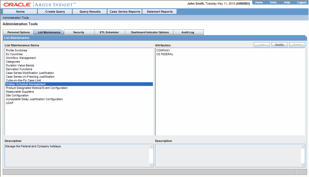
When the system opens the Holiday Schedule Management dialog box, select the appropriate holiday selections and click OK.
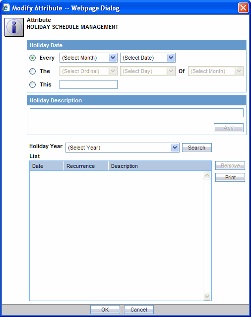
The system returns to List Maintenance.
Select All Configurations under Attributes from List Maintenance Items - Product Designated Medical Event Configuration. Click Modify.
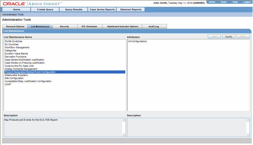
When the system opens the Product Designated Medical Event Configuration dialog box, make the required selections and click OK.
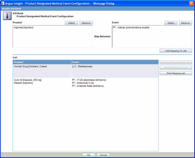
The system returns to List Maintenance.
Select All Configurations under Attributes from List Maintenance Items - Measurable Suppliers. Click Modify.
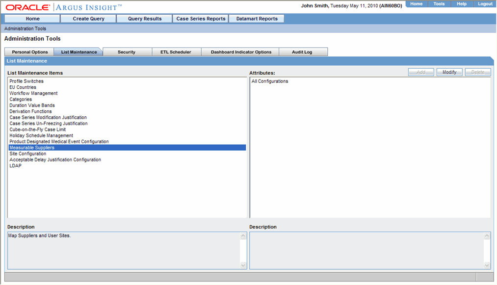
Make the appropriate selections and click OK.
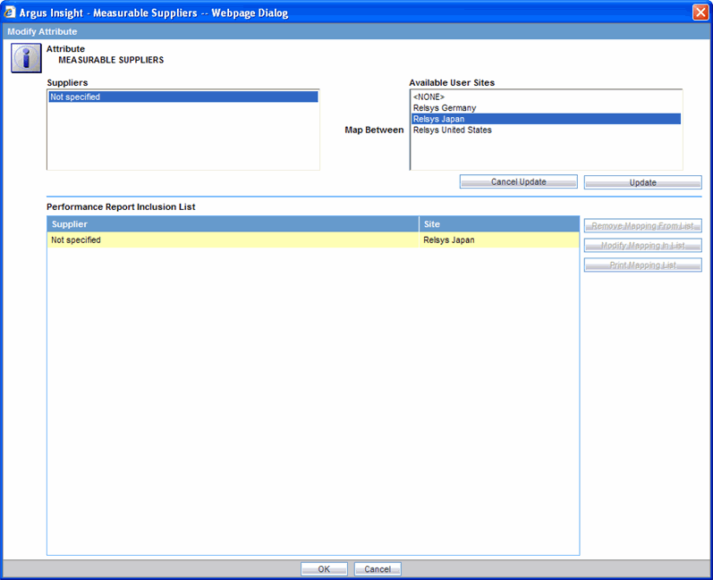
The system returns to List Maintenance.
Click the Logout button in the upper-left corner of the page to exit Argus Insight.
Use the following procedure to configure Sites.
Login to the Argus Insight application.
Go to Admin Tools > List Maintenance.
Select Non-Core Site Configuration under Attributes from List Maintenance Items - Site Configuration. Click Modify.
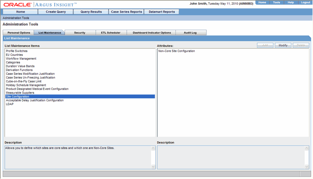
When the system opens the Site Configuration dialog box, select core and non-core sites. The system uses this configuration in the DCA-TME Notification Report in Case Processing.
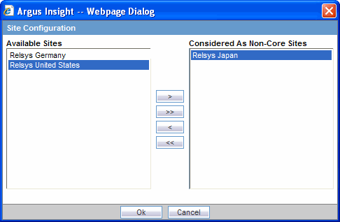
Click OK to return to the List Maintenance page.
Use the following procedure to configure Acceptable Delay Justification:
Login to the Argus Insight application.
Go to Admin Tools > List Maintenance.
Select Acceptable Routing Delay Justification and Acceptable Submission Delay Justification under Attributes from List Maintenance Items - Acceptable Delay Justification.
Select one of the attributes and click Modify.
This dialog enables you to understand whether the delay in report submission is justified or not.
This configuration is used in the Regulatory Submission and Distribution Compliance Report in Compliance.
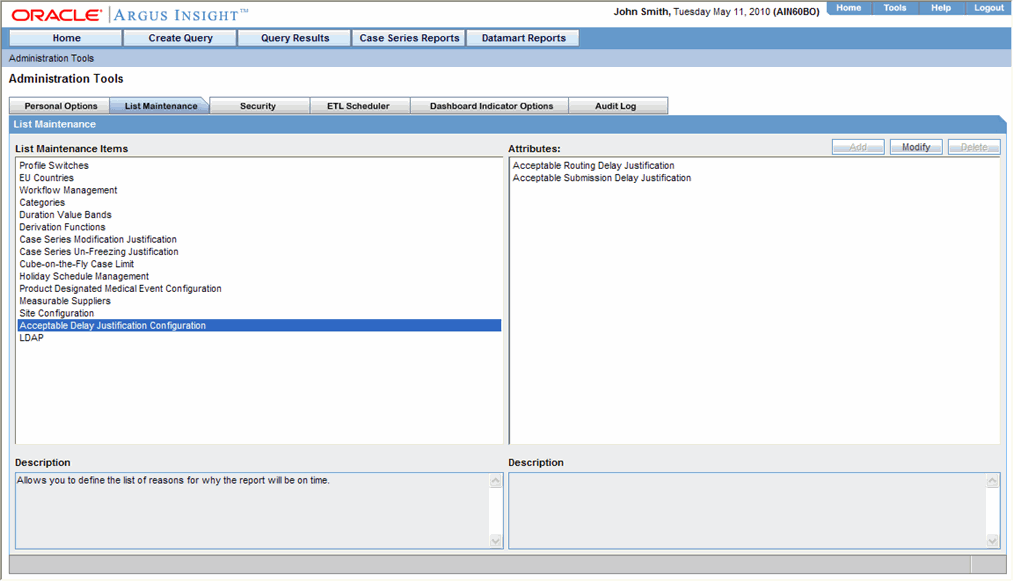
Make the required selections and click OK to return to the List Maintenance page.
This topic has instructions on integrating the LDAP authentication with Argus Insight and BOXI. Follow the installation procedures in the order in which they appear in this topic.
|
Note: Create a group in the LDAP server and assign LDAP users to this group. This group should not exist in BOXI. |
This section explains the procedure for configuring the LDAP server settings in the BOXI. The steps follow:
Login to BOXI CMS using the administrator name and password.
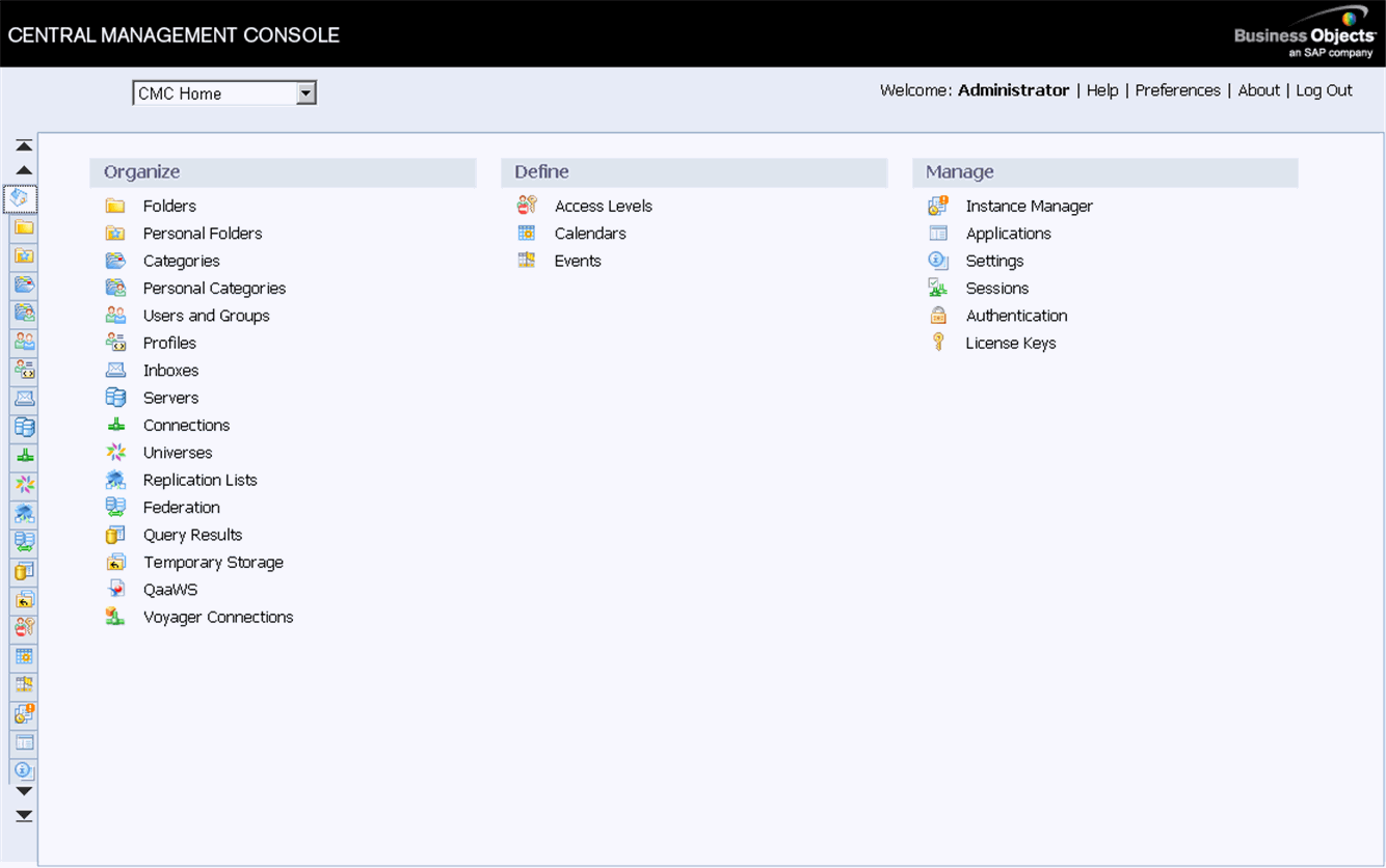
When the system opens the Central Management Console, click Authentication to access the authentication options in BOXI.
Double-click LDAP.
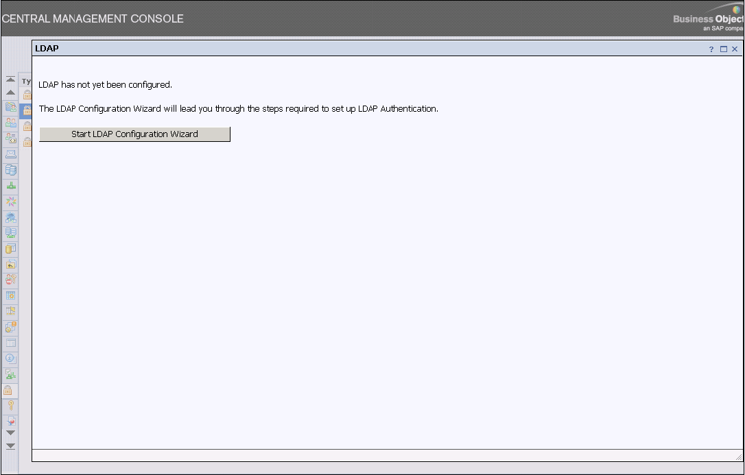
When the LDAP tab opens, click Start LDAP Configuration Wizard.
When the system opens the following screen, add the LDAP server IP Address and port number. Click Next.

When the system opens the following screen, click Next.

When the system opens the following screen, enter the Base LDAP Distinguished Name and click Next.

When the system opens the following screen, click Next.
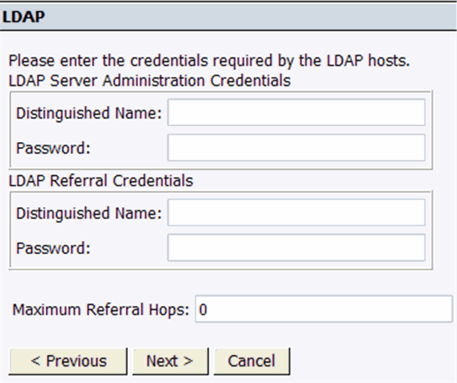
When the system opens the following screen, click Next.

When the system opens the following screen, click Next.
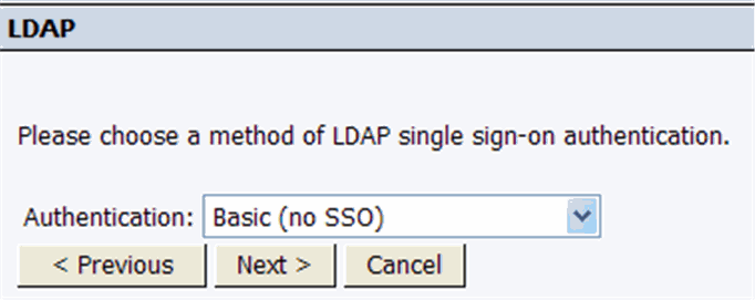
When the system opens the following screen, locate the New User Options section and select Named or Concurrent as required. Click Next.
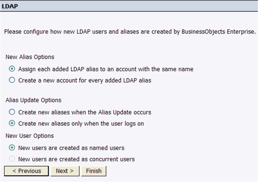
Click Next. The following screen appears.
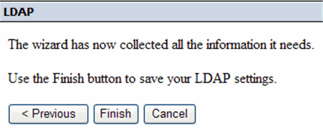
When the system opens the following screen, click Finish. The following screen appears.
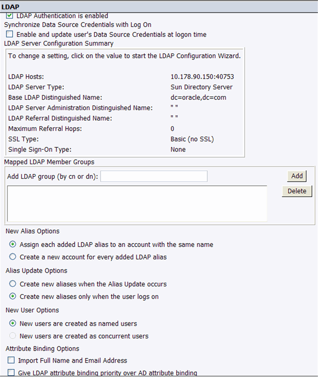
When the system opens the following screen, locate the Add LDAP group (by cn or dn) and type the Group Name configured in LDAP server. Click Add.
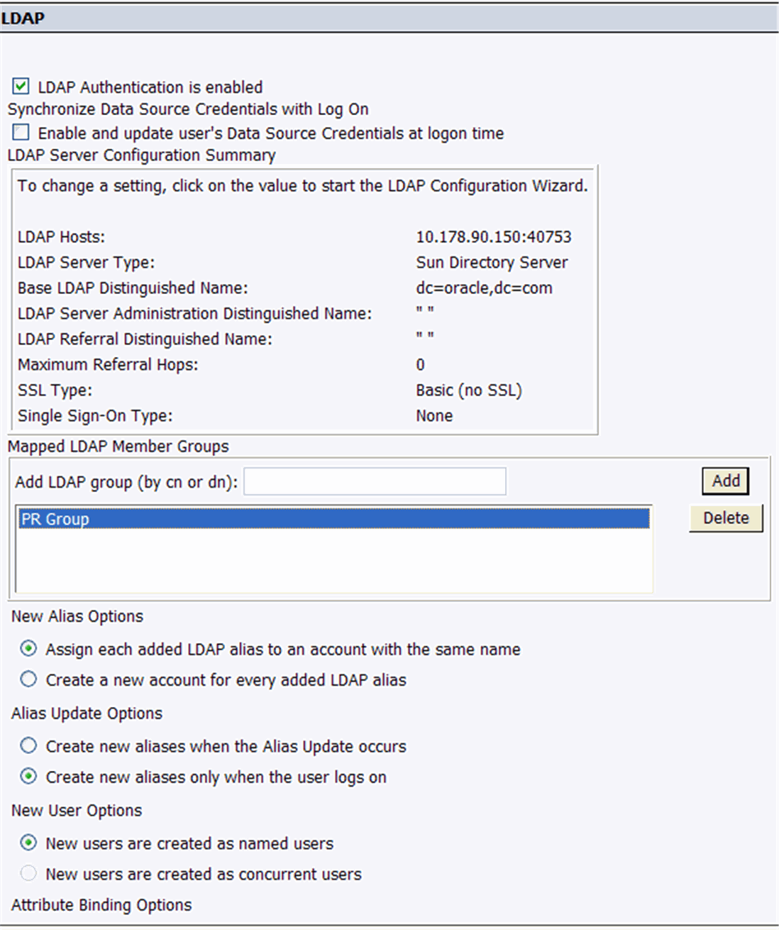
When the system opens the following screen, scroll downwards and click Update.
The system opens the following screen with the LDAP server settings.
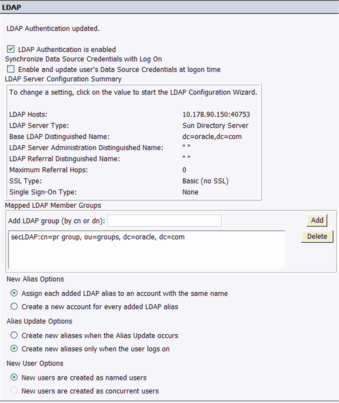
Map the LDAP member group whose users you want to authenticate through LDAP.
For example, PR Group shown above is the member group whose users are part of Argus Insight and use LDAP authentication while getting authenticated on business objects.
Select the following options on LDAP configuration screen:
Create a new account for every added LDAP alias.
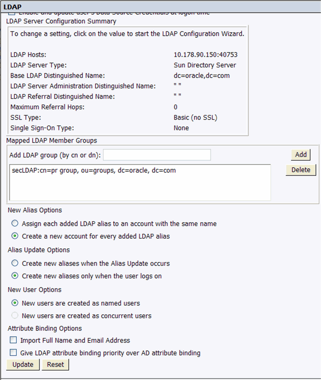
Close the window and go to Home > Groups and select the PR Group.

Right-click the PR Group (LDAP) and select Member of.
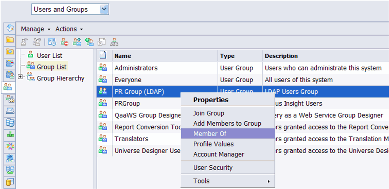
Click Join Group in the following screen.

The following screen appears. Go to Group List > PR Group and click > to add the PRGroup into the Destination Group.
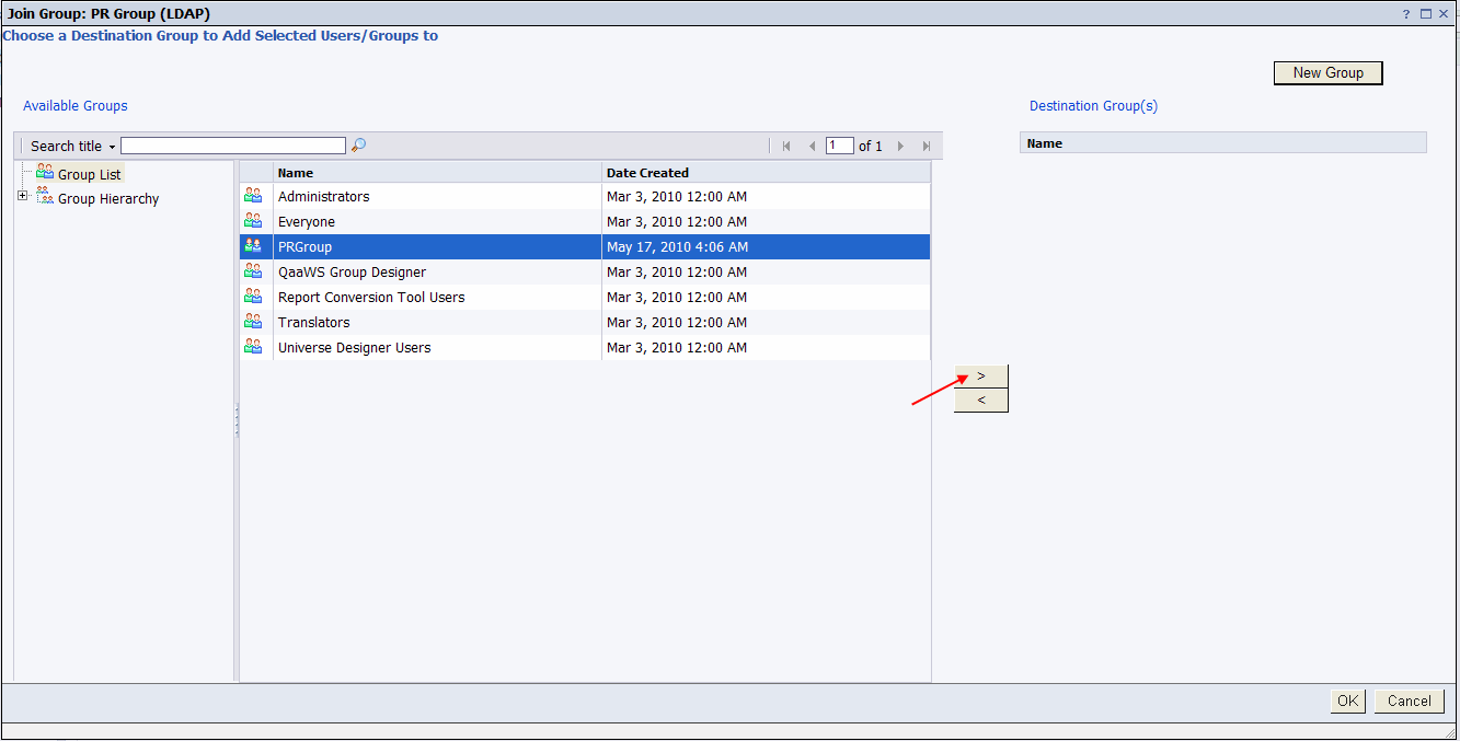
The PRGroup is added under the Destination Group. Click OK.
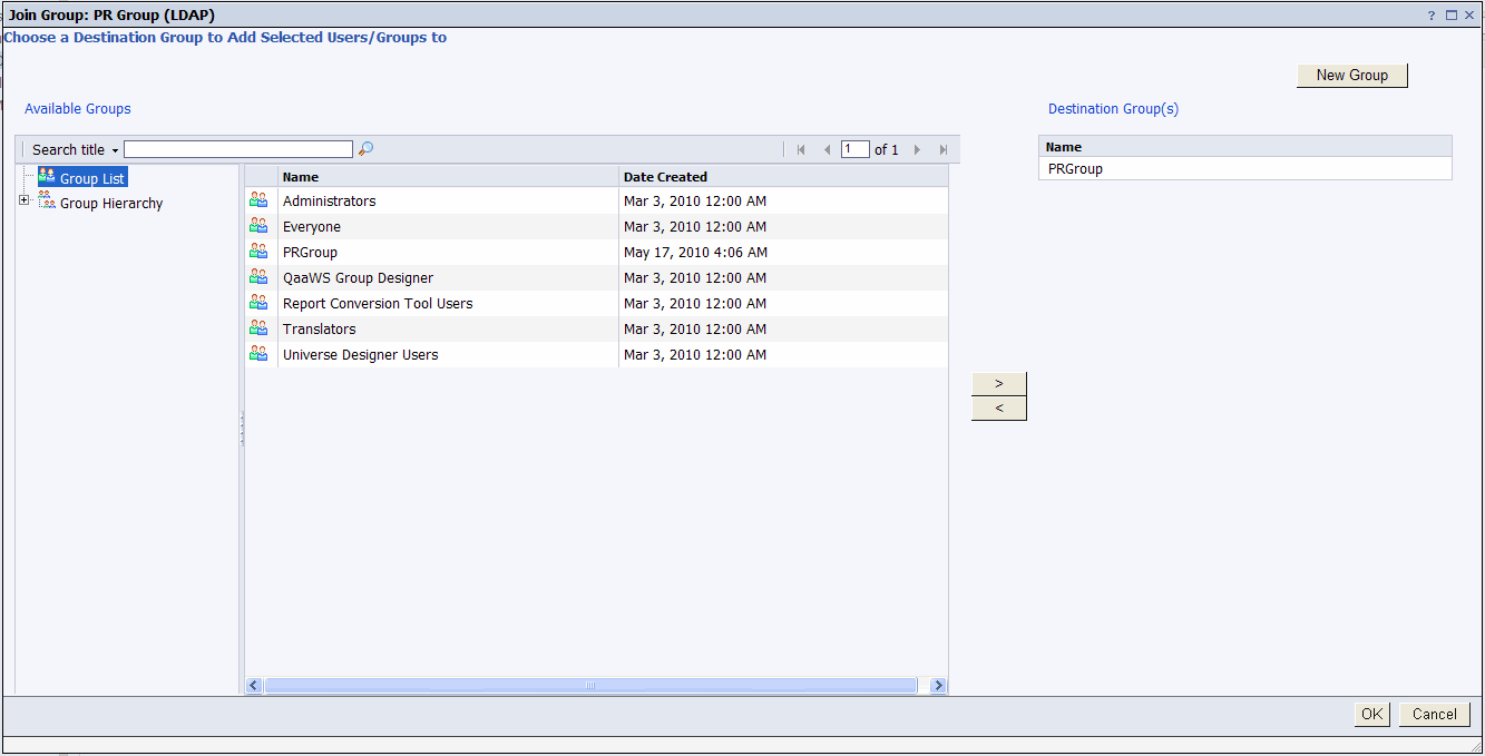
The PR Group (LDAP) is added and displayed as a member of the PRGroup.

Use the following procedure to set up the LDAP configuration in Argus Insight.
Go to Tools > List Maintenance to open the List Maintenance tab.
When the system opens the List Maintenance tab, select LDAP in the left pane.
Select LDAP Configuration from the right pane of the tab. Click Modify.
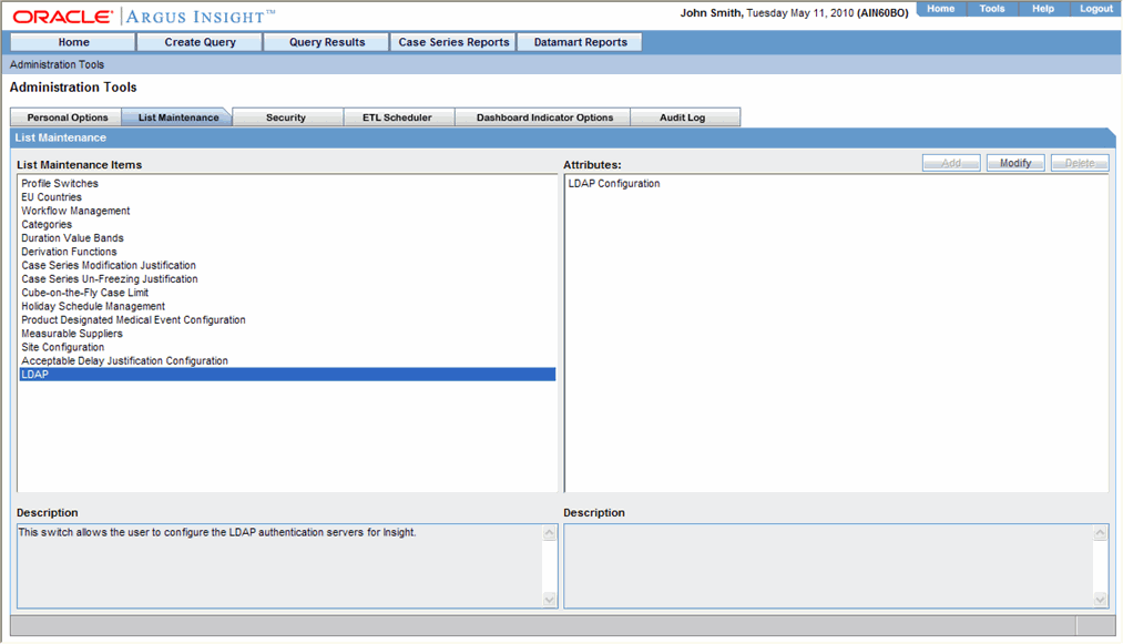
When the system opens the following dialog box:
Locate the Enable LDAP at system level field and click the Yes option button.
Click Add.
|
Note: The entire LDAP configuration imported from Argus Safety via ETL is in read-only mode. |
When the system opens the following dialog box, set the parameters.
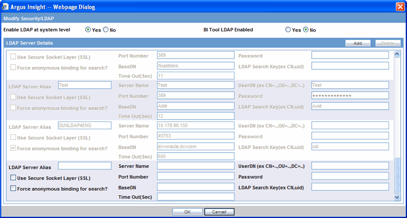
The following table lists and describes the parameters.
| Parameter Name | Description |
| LDAP Server Alias | Enter a unique name to identify the LDAP server configuration. |
| Server Name | Enter the name of the LDAP server. |
| Port Number | Enter the LDAP server port number. |
| BaseDN | Enter the Base DN for configured LDAP server (distinguish Name). |
| Time Out(Sec) | Enter a value for LDAP search timeout. |
| UserDN(ex. CN=..,OU=..,DC=..,): | Enter the complete UserDN for the LDAP search user. Argus Insight uses this user to search for users in the complete LDAP directory for authentication. |
| Password | Enter password for the LDAP search user. |
| LDAP Search Key(ex. CN,uid): | Enter SAMAccountName for Active Directory Server
|
This topic has instructions on Windows Firewall troubleshooting.
Issue Description:
When Windows Firewall is ON at the BOXI server, the user experiences trouble while accessing BOXI server data through Argus Insight application. Typical example is when we run any standard report from Argus Insight application. Then, while loading the pre-filter page, it throws the error and the user has to abort the process.
Issue Resolution:
This issue can be resolved in one of the following two ways:
A) Turn- off the firewall
However, this resolution may not be acceptable to all the clients as some clients rely on Windows Firewall for securing their servers.
B) Modify server settings and add additional ports in the Firewall
Part 1 - Modify the settings of some servers through the BOXI Central Management Console.
Part 2 - Add and open some additional ports in Windows Firewall.
Part 1: Execute the following steps to modify the settings of servers
Log into the BOXI server.
Open the Central Management Console.
Go to Servers. The following screen is displayed.
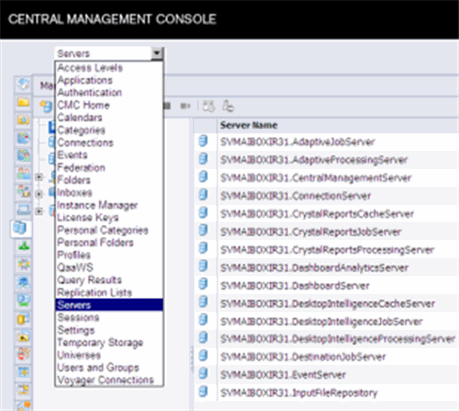
Under Server Name, right-click Central Management Server and click Properties.
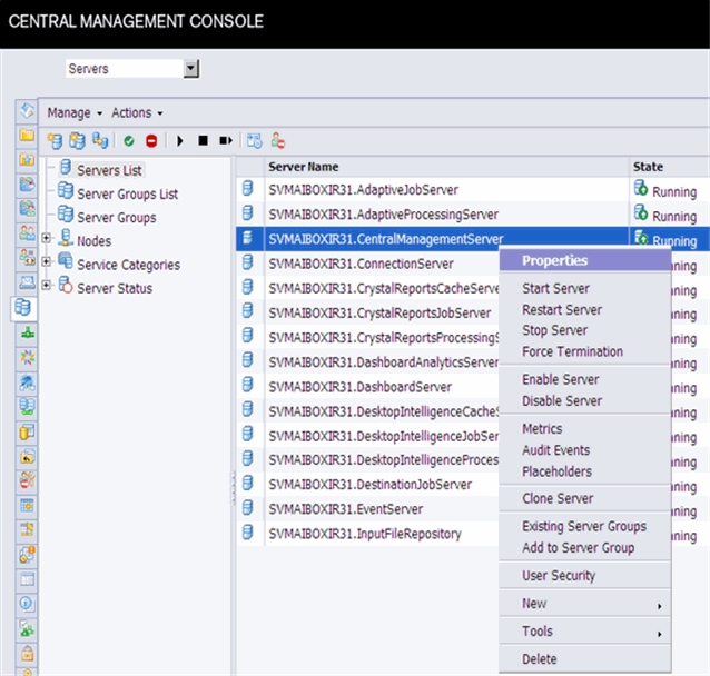
The Properties screen is displayed. Under Common Settings, clear the Auto assign radio button, and add an available port number in Request Port, such as 6411 in the example below.
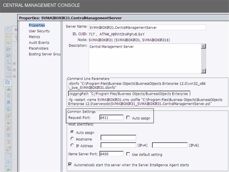
Click Save and Close.
Right-click Central Management Server and select Restart Server.
On coming back to the Servers List page shown below, under Server Name, right-click the Desktop Intelligence Cache Server and click Properties.
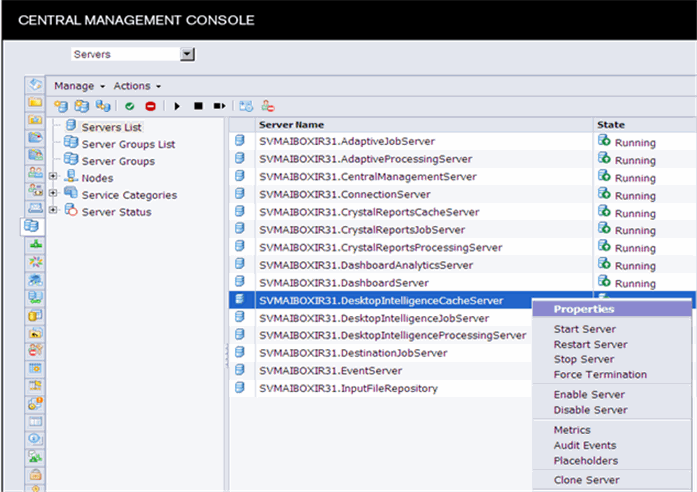
The Properties screen is displayed. Under Common Settings, clear the Auto assign radio button, and add an available port number in Request Port, such as 6600 in the example below.
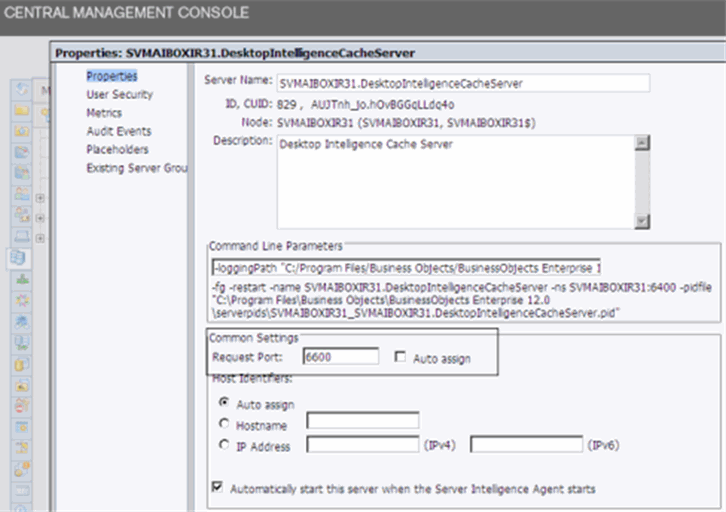
Click Save and Close.
Right-click Desktop Intelligence Cache Server and select Restart Server.
Close the Central Management Console.
Part 2: Modify the Window Firewall settings
Open Windows Firewall on the BOXI server.
Click the Exception tab, as shown below. 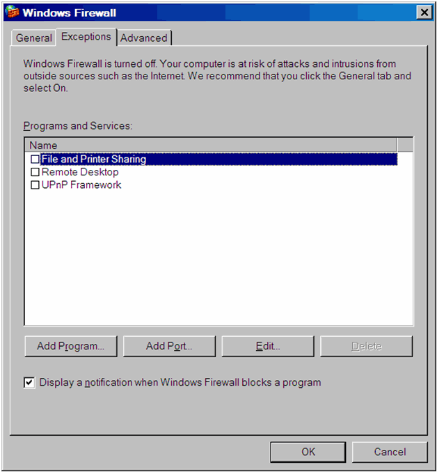
Click the Add Port... button. The Add a Port dialog is displayed. 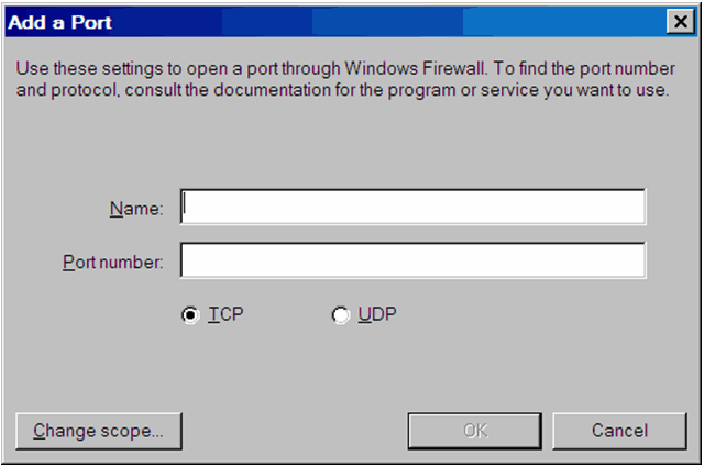
Enter the Name.
Enter the Port Number as 6400 and click OK.
Click Add Port again.
Enter another new Name.
Enter the Port Number as 6411 and click OK. (This should be the same as of Part I, Step 5)
Click Add Port again.
Enter another new Name.
Enter the Port Number as 6600 and click OK. (This should be the same as of Part I, Step 8)
Click Add Port again.
Enter Name. Enter Port Number as <the Port Number on which the Argus Insight application is installed>. By default, this is Port Number 8084. Click OK.
Optional: If you want to access the BOXI Central Management Console from any other machine, click Add Port. Enter the Name. Enter the Port Number as <the Port Number on which the BOXI CMC is installed>. By default, this is Port Number 8080. Click OK.
Click OK.
Resolution Verification:
Once the above steps are executed, you can verify the resolution by logging into the Argus Insight application and executing any standard report successfully, without any errors.