| C H A P T E R 3 |
|
Installing and Replacing Server Blades |
This chapter provides the steps required to install and replace B100x blade
(single-width) and B200x (double-width) blades in the Sun Fire B1600 blade system chassis. The chapter contains the following sections:
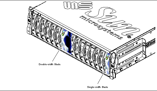
The system chassis contains 16 slots. It can hold a combination of single-width blades, double-width blades and filler panels. Double-width blades occupy two adjacent slots in the system chassis.
FIGURE 3-1 shows a system chassis containing single-width blades and a
double-width blade.
|
Note - Be aware that the system chassis contains three internal dividing walls. Double-width blades must be installed in two available slots between these internal dividing walls. |

|
Caution - Do not leave any slots empty as this can disrupt airflow through the system and compromise EMC performance. |
 To shut down the blade in preparation for removal, and to cause the blue "Ready to Remove" LED to be lit, type:
Where n is the number of the slot containing the blade you are removing.
The steps in this section refer to removal of a single-width blade. The same steps apply when removing a double-width blade or filler panel.
1. If you are removing a blade, check that the blue "Ready to Remove" LED is lit.
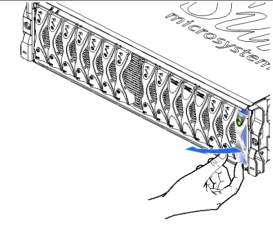
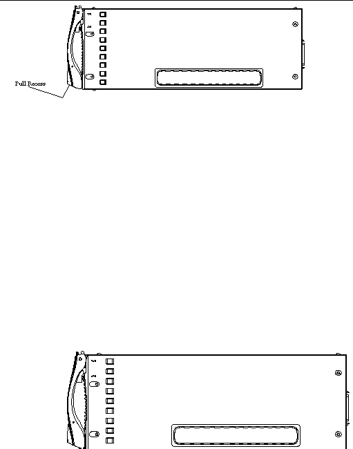
2. Insert your finger in the pull recess located at the bottom front of the blade lever and pull gently to disengage the locking mechanism (FIGURE 3-2).
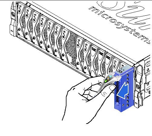
3. Pull the lever in a forward and upward motion, causing the blade lever to unlatch and eject the blade partially from the system chassis (FIGURE 3-3).
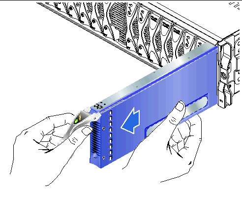
4. Pull the lever to remove the blade from the system chassis (FIGURE 3-4).
Support the bottom of the blade with your free hand while lifting the filler panel clear of the system chassis.
The system chassis is designed to operate with a total of up to 16 blades and filler panels installed.

|
Caution - Do not leave any slots empty as this can disrupt airflow through the system and compromise EMC performance. |
|
Note - Be aware that the system chassis contains three internal dividing walls. Double-width blades must be installed in two available slots between these internal dividing walls. |
The steps below refer to installation of a single-width blade. The same steps apply when installing a filler panel or double-width blade.
If required, open the blade lever by inserting a finger in the pull recess located in lower portion of the blade lever and pull the lever in a forward and upward motion, causing the lever to unlatch (FIGURE 3-5).
5. Align the blade with the empty slot.
Ensure that the blade connector is facing towards the system chassis, with the hinge point of the lever mechanism at the top. Support the bottom of the blade with your free hand while lifting the blade up to the system chassis (FIGURE 3-6).
6. Insert the blade into the selected system chassis slot (FIGURE 3-6).

|
Caution - Ensure that the blade engages with the system chassis guidance system. Failure to align the blade correctly can result in damage to the chassis midplane or the blade connection. |
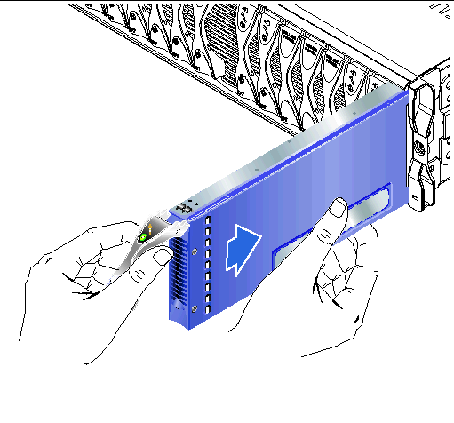
7. Gently push the blade into the slot until the blade latch ears, on top of the lever, are positioned in the chassis.
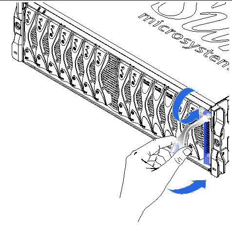
8. Close the blade lever fully by pushing it down until you feel the latch click in place.
This engages the blade with the connectors in the chassis slot (FIGURE 3-7). When you do this, the LEDs on the blade flash several times.
|
Note - For information interpreting LEDs on a blade, see the Sun Fire B1600 Blade System Chassis Administration Guide |
Copyright © 2004, Sun Microsystems, Inc. All rights reserved.