| C H A P T E R 7 |
|
Using Linux Blades in Separated Data and Management Networks |
This chapter contains the following sections:
This chapter tells you how to set up the Sun Fire B1600 blade system chassis for use in an environment that separates the data and management networks. If you have dual SSCs installed in the chassis, the instructions enable you to take advantage of the presence of two switches to give the server blades two connections to each of your networks.
This chapter also explains how to take advantage of the presence of two switches by using failover and link aggregation to provide fully redundant connections from Linux server blades to the data and management networks.
To take advantage of the redundancy offered by the second switch inside the system chassis, we recommend you to:
If you are using DHCP, make sure that the DHCP server for the System Controllers and switches is on the management network, and that the DHCP server for the blades is on the data network.
|
Note - The example in Preparing the Network Environment Using DHCP uses static IP addresses, not DHCP. |
For information on setting up the etc/dhcp.conf file, see Chapter 4.
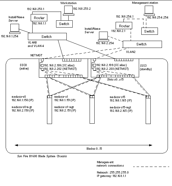
FIGURE 7-1 shows a sample network configuration with the 100Mbps network management port (NETMGT) on both SSCs connected to a different switch from the data uplink ports. This external switch is on a different subnet than the switch that the data uplink ports on the chassis are connected to. It is a subnet dedicated to network management traffic and it therefore also contains both of the System Controllers and switches in the chassis. A management VLAN (VLAN 2) contains both System Controller interfaces and both switch management ports. All the server blades and uplink ports are on the untagged VLAN 1.
FIGURE 7-1 shows the connection of the snet0 interface on B100x blades to the switch in SSC0, and the connection of the snet1 interface on B100x blades to the switch in SSC1. It also shows the connection of snet0 and snet2 interfaces a B200x blade to the switch in SSC0, and the connection of the snet1 and snet3 interfaces on a B200x blade to the switch in SSC1. The IP address of the blade is used by the Failover interfaces to enable failover and link aggregation (see Section 7.4.1, Setting up Linux Server Blades Using the Failover Interface Driver for Network Resiliency).
One or more of the eight uplink ports on each switch in FIGURE 7-1 are connected to an external switch that has an Install Server connected to it. This external switch also has a router (with IP address 192.168.1.1) connected to it that acts as the default gateway from the chassis to the wider network.
|
Note - that there is no direct network connection in FIGURE 7-1 from the management port (NETMGT) in the switch to the server blade ports. This means that, by default, you cannot manage the server blades directly from the management network. This is a security feature to protect the management network from the possibility of hostile attack from the data network. For information about permitting specified traffic from the server blades to the management port, see the example in Example Network Configuration. |
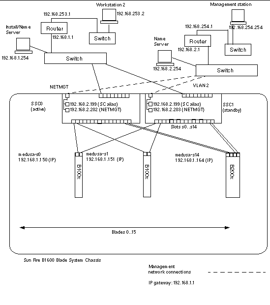
To configure the System Controllers and switches for the type of configuration illustrated in FIGURE 7-1, follow the instructions in the Software Setup Guide. However, remember that the IP addresses you assign to the System Controllers and switches need to be on the management subnet.
To set up a fully configured blade that provides redundant connections to the data and management networks, you will need to configure a number of interfaces.
There are four types of network interface:
These are the standard physical Gigabit Ethernet interfaces on the blade. On a B100x blade, these are snet0 and snet1. On a B200x blade these are snet0 and snet1, and snet2 and snet3.
To provide consistency with interface order, the standard physical Ethernet interfaces have been renamed from "eth" to "snet".
Bonding interfaces use link aggregation to combine the four ethernet interfaces on a B200x blade into two pairs of interfaces, each with a single MAC address. Link aggregation provides 802.3ad interfaces called BOND0 and BOND1.
VLAN interfaces are the virtual interfaces that can be configured on top of physical interfaces or bond interfaces. VLAN support is provided by the sun8021q driver.
Failover support for the switches in SSC0 and SSC1 is provided through failover redundancy interfaces called fail0 and fail1.
It is useful to think of these interfaces as layers, with the physical interface as the bottom layer, and the failover interface as the top layer. The example configurations in the next section demonstrate how these layered interfaces can be configured to provide failover.
This section provides sample network interface configurations for server blades.
FIGURE 7-2 shows a failover interface (fail0) configured to provide redundancy between the physical interfaces snet0 and snet1 on a B100x server blade.
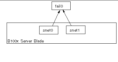
FIGURE 7-3 shows two failover interfaces (fail0 and fail1) configured to provide redundancy between two pairs of physical interfaces on a B200x server blade. Fail0 provides redundancy between snet0 and snet1, and fail1 provides redundancy between snet2 and snet3.
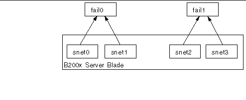
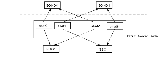
FIGURE 7-4 shows a B200x blade with a bonding interface layer configured to combine the four ethernet interfaces on the blade into two pairs of interfaces, each with a single MAC address. In the bonding interface layer, snet0 and snet2 become a single interface (BOND0), and snet1 and snet3 become a single interface (BOND1).
To enable failover between the two switches, a failover interface (fail0) has been configured on top of the bonding interface. Fail0 provides redundancy between BOND0 and BOND1.
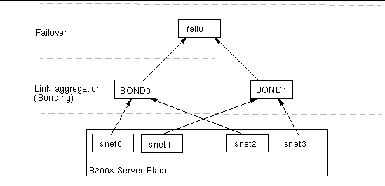
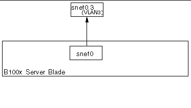
FIGURE 7-5 shows a B100x blade with a VLAN3 interface configured on a physical interface (snet0). Note that the VLAN interface name comprises the name of the physical interface (snet0), followed by the VLAN number (.3). Therefore, in this example, the VLAN interface name is snet0.3.
shows a B100x server blade with two VLAN interfaces (snet0.3 and snet1.3) configured on top of the physical interfaces (snet0 and snet1). A failover interface (fail0) has been configured on top of the VLAN interface. Fail0 provides redundancy between snet0.3 and snet1.3.
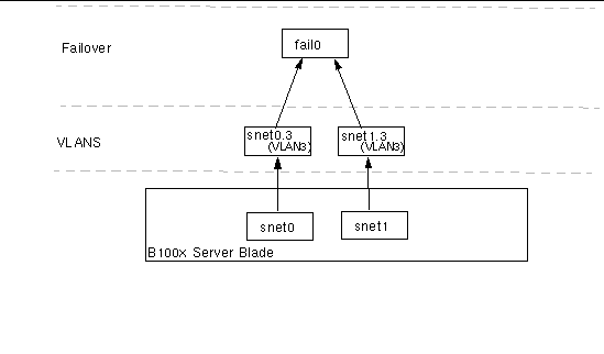
FIGURE 7-7FIGURE 7-7 shows a B200x server blade with four VLAN3 interfaces (snet0.3, snet1.3, snet2.3 and snet3.3) configured on top of four physical interfaces. Failover interface fail0 has been configured on top of snet0.3 and snet1.3, and fail1 has been configured on top of snet2.3 and snet3.3.
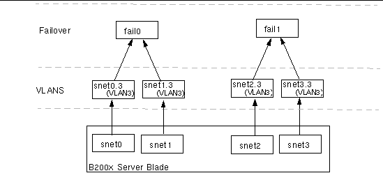
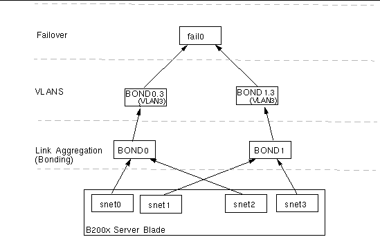
FIGURE 7-8 shows a B200x blade with failover between two VLAN interfaces that are configured on aggregated links.
A bonding interface layer has been configured to combine the four ethernet interfaces on the blade into two pairs of interfaces, each with a single MAC address. Therefore, in the bonding interface layer, snet0 and snet2 become a single interface (BOND0), and snet1 and snet3 become a single interface (BOND1).
A VLAN3 interface layer has been configured on top of the bonding interface layer to provide two VLAN interfaces called BOND0.3 and BOND1.3.
To enable failover between the two switches, a failover interface (fail0) has been configured on top of the VLAN interfaces. Fail0 provides redundancy between BOND0.3 and BOND1.3.
Bonding interfaces are used to provide link aggregation for B200x server blades. Link aggregation allows you to combine the four ethernet interfaces on the blade into two pairs of interfaces, each with a single MAC address. Therefore, snet0 and snet2 become a single interface to SSC0, and snet1 and snet3 become a single interface to SSC1. When the Sun Fire B1600 blade system chassis is fully operational, both switches are constantly active.
Link aggregation is achieved by using the Bonding driver to set up two bonding interfaces to enslave each pair of ethernet interfaces. In Red Hat el-3.0 the full 802.3ad specification is supported. In other versions of Linux, a simple
active-backup protocol is used. Note that the Bonding driver can only be configured on top of physical interfaces.
To use link aggregation you must also configure the switches to accept the aggregated links. You do this by either enabling LACP (link aggregation control protocol, which is available with Red Hat el-3.0 only) or by setting up port-channels for the blade that uses aggregated links to the switch. For more information, see Configuring the Switch for Link Aggregation.
The Bonding driver is used to provide Link aggregation, and is initially configured using module parameters when the driver is loaded. You must then associate physical interfaces to the bond interfaces manually using the ifenslave utility.
The module parameters configure the number of bond interfaces and their behavior. These module parameters are set in the /etc/modules.conf file. The parameters are:
You need to associate physical interfaces to the bond interfaces using the ifenslave utility. The ifenslave utility enslaves physical interfaces as slaves to the bond master. For example,
enslaves snet0 and snet2 to bond0.
The location of ifcfg files depends on the version of Linux you are running:
CODE EXAMPLE 7-3 shows a bond interface (ifcfg-bond0) that enslaves snet0 and snet2 to provide link aggregation.
|
ONBOOT must be set to "yes". This means that the interface is configured at boot time. |
The instructions in this section tell you how to configure the two switches to accept aggregated links from a B200x blade. The method you use to configure the switches will depend on the version of Linux you are running. For Red Hat el-3.0, which supports 802.3AD, follow the instructions in Configuring the Switch for Link Aggregation with Red Hat el-3.0 (Using LACP). For earlier versions of Red Hat, and SuSE, follow the instructions in Configuring the Switch for Link Aggregation Using Active-Backup.
The following steps tell you how to configure the switch for link aggregation if you are using Red Hat el-3.0. They use an example B200x server blade in slots 14 and 15.
1. To log into the switch in SSC0, type:
2. When prompted, type the username and password for the switch.
5. Repeat Step 1 through Step 4 for the switch in SSC1.
The following steps tell you how to configure the switch for link aggregation if you are using active-backup. Active-backup is used with SuSE, and releases of Red Hat earlier than Red Hat el-3.0. The instructions use an example B200x server blade in slots 14 and 15.
1. To log into the switch in SSC0, type:
2. When prompted, type the username and password for the switch.
3. Set up a port-channel for the default configuration.
4. Bind the Ethernet interface for slot 14 into the port-channel.
5. Bind the Ethernet interface for slot 15 into the port-channel.
6. Repeat Step 1 through Step 5 for the switch in SSC1.
VLANs are a virtual interface that can be configured on physical interfaces or on bonding interfaces. For example, you can configure a VLAN interface on Ethernet snet0 (a physical interface), or on BOND0 (a virtual interface). VLAN support is provided by the sun8021q driver.
For VLANs to work correctly, both the blade and the switch ports for that blade need to be configured. The VLAN interfaces are configured using the sunvconfig utility.
This section tells you how to configure a server blade so that the Ethernet interface provides an active logical interface to a VLAN. In the example shown, snet0 provides an interface to VLAN 3.
To create VLAN 3 on top of snet0 use the sunvconfig utility.
This creates a VLAN3 interface which is configured on snet0. All network packets sent through this interface will have a VLAN tag of 3 added.
You can ensure that VLAN settings are maintained after a reboot by editing the ifcfg-snet0.3 file.
The location of ifcfg files depends on the version of Linux you are running:
CODE EXAMPLE 7-2 shows an example ifcfg-snet0.3 file.
The switch must also be configured to accept tagged VLAN traffic from the blades. The instructions in this section tell you how to add the server blades to the VLAN 3. If you are configuring for switch failover, you must add server blades to the switches in both SSC0 and in SSC1.
|
Note - If you reset the switch while you are performing the instructions in this section, you must save the configuration first. If you do not, you will lose all of your changes. |
1. From the sc> prompt, log into the console to configure the switch in SSC0.
To log into the switch in SSC0, type:
2. When prompted, type your user name and password.
3. At the Console# prompt on the switch's command line, type:
4. Enter the switch's VLAN database by typing:
6. Exit the vlan database by typing:
7. Add the server blade port SNP0 to the data VLAN (VLAN 3).
To do this, type the following commands:
Console#configure Console(config)#interface ethernet SNP0 Console(config-if)#switchport allowed vlan add 3 tagged Console(config-if)#exit Console(config)# |
The meaning of this sequence is as follows:
Repeat Step 7 for all the remaining server blade ports (SNP1 through SNP15). All of these ports need to be included in both the management network and the data network.
To inspect the port you have configured, type:
8. If required, copy the configuration of the switch in SSC0 on to the switch in SSC1.
Follow the instructions in the Sun Fire B1600 Blade System Chassis Software Setup Guide, Appendix A.
Network resiliency is provided using the Failover interface driver. The failover interface can be used with physical interfaces, and virtual interfaces, such as bond interfaces (used with link aggregation) or VLAN interfaces.
The Failover interface driver enslaves two interfaces. These two interfaces should each provide a path to a different switch in the chassis. For example, for failover between physical interfaces on a B100x blade, snet0 and snet1 can be enslaved. On the B200x blade, snet0 and snet1 can be enslaved, and so can snet2 and snet3.
When providing failover between virtual interfaces such as VLANs or aggregated links, these interfaces must also provide a path to different switches. Therefore, the physical interfaces underlying the virtual interfaces must be configured so that each enslaved interface has a path to a different switch in the chassis.
The instructions in this section tell you how to use the Failover interface driver to take advantage of the redundant connections from each Linux server blade to the two switches in the chassis.
The Failover interface driver works by enslaving the network interfaces on a server blade. It detects link availability by periodically arping the arp targets from the Ethernet interfaces. This means that if for any reason all of the arps fail on a given interface (indicating that the path to the network is no longer available on the interface that was used to perform the arp) the failover interface ensures that network traffic uses only the interface that remains valid.
The targets used for arping should be the default gateways for the Ethernet interfaces. You can configure arp targets using the failarp utility. The failarp utility looks in the routing table for gateways which it sets as the targets for the failover interface. Alternatively you can specify arp targets manually when you set up the failover interface.
You can configure failover interfaces manually using the failctl utility. Alternatively, you can edit the ifcfg files provided in/etc/sysconfig/network-scripts/.
To enable failover between the two switches you must configure a failover interface (fail0 in FIGURE 7-10). The failover interface works by enslaving snet0 and snet1 and detecting link availability by periodically arping the arp targets through the Ethernet interfaces. If arps fail on snet0 the failover interface ensures that network traffic uses snet1, and vice versa.
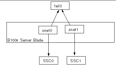
You can configure failover interfaces manually using the failctl utility. The steps in this section tell you how to configure fail0 to provide failover between the two switches (as shown in FIGURE 7-10). For the purposes of illustration the instructions use a sample configuration input from the network scenario illustrated in the section Preparing the Network Environment Using DHCP.
|
Note - You need to perform the instructions in this section on each B100x server blade that requires a redundant connection to the network. |
TABLE 7-3 summarizes the information you would need to give to the Failover Interface Driver on the server blade as illustrated in FIGURE 7-1.
1. Log into the console of the server blade whose interfaces you want to configure. Type the following at the sc> prompt:
where n is the number of the slot containing the server blade you want to log into.
2. Enslave the two Ethernet devices on the blade using the failctl command.
3. Configure static arp targets for fail0.
4. Configure the arp interval used to check link availability. The arp interval is measured in milliseconds (ms).
where nnnnn is the number of milliseconds required for the arp intervals.
5. Set up a static IP address for fail0.
|
Note - Alternatively you can configure the failover interface to obtain IP addresses using DHCP. |
|
Note - You can maintain the failover interface configurations after rebooting by editing the ifcfg-fail files in /etc/sysconfig/network-scripts (or /etc/sysconfig/network-scripts, if you are running SuSE.) For more information, see Example ifcfg-fail0 File for a B100x Server Blade. |
CODE EXAMPLE 7-3 shows an ifcfg-fail0 file that provides failover between the two switches.
DEVICE=fail0 CHILDREN="snet0 snet1" ONBOOT=yes BOOTPROTO=none IPADRR=192.168.1.150 NETMASK=255.255.255.0 ARP_INTERVAL=10000 #ARP_TARGET=192.168.1.1 #failarp(8) is used if ARP_TARGET isn't specified. |
The example in this section (FIGURE 7-11) shows a network configuration where server blades are added to the management VLAN, which is VLAN 2 by default. VLAN 1 is also set up by default on the switch. This VLAN contains all the switch's server blade and uplink ports. However, to demonstrate the use of the switch's VLAN configuration facilities, the example uses VLAN 3 instead of VLAN 1 for the data network.
In this example the management VLAN (VLAN 2) and the data VLAN (VLAN 3) are tagged. However, the example also shows an additional VLAN for blade booting (VLAN 4). This handles untagged traffic generated by the blades during the PXE boot installation process.
This traffic on the boot VLAN (VLAN 4) can be tagged or untagged when it leaves the system chassis. In the sample commands in this section it is tagged. (The instructions in this section assume that the devices outside the chassis are VLAN-aware, and VLAN 4 is assumed to contain the PXE boot installation server used by the server blades.)
The example in this section uses full redundancy to the switches in SSC0 and SSC1, and link aggregation.
 [ D ]
[ D ]
To support the configuration in FIGURE 7-11 on a B200x blade, you must configure three network interface layers, as illustrated in FIGURE 7-12.
Two bonding interfaces must be configured to provide aggregated links that combine the four ethernet interfaces on a B200x blade into two pairs of interfaces BOND0 provides link aggregation for the physical interfaces snet0 and snet2, and BOND1 provides link aggregation for the physical interfaces snet1 and snet3.
Two VLAN3 interfaces (BOND0.3 and BOND1.3) are configured on top of the two aggregated links (BOND0 and BOND1), and two VLAN2 interfaces (BOND0.2 and BOND1.2) are configured on top of the same two aggregated links.
To provide redundancy between the two switches, two failover interfaces must be configured on top of the VLAN interface layer. The fail1 interface provides failover for the two VLAN3 interfaces (BOND0.3 and BOND1.3). The fail2 interface provides failover for two VLAN2 interfaces (BOND0.2 and BOND1.2).
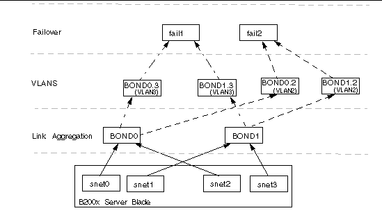
You configure these network interfaces by editing ifcfg files for snet0, snet1, snet2, snet3, BOND0, BOND1, BOND0.2, BOND1.2, BOND0.3, BOND1.3, fail1 and fail2.
Refer to the following code examples for information on editing the ifcfg files. The location of ifcfg files depends on the version of Linux you are running:
DEVICE=fail1 CHILDREN="bond0.3 bond1.3" ONBOOT=yes IPADDR=192.168.1.164 [ $ONBOOT = no ] || . ifinit |
DEVICE=fail2 CHILDREN="bond0.2 bond1.2" ONBOOT=yes IPADDR=192.168.2.164 [ $ONBOOT = no ] || . ifinit |
To support the configuration in FIGURE 7-11, you will need to add the server blades to the management and data VLANs on the switches in SSC0 and SSC1.
1. From the sc> prompt, log into the console to configure the switch in SSC0.
To log into the switch in SSC0, type:
2. When prompted, type your user name and password.
3. At the Console# prompt on the switch's command line, type:
4. Enter the switch's VLAN database by typing:
5. Set up the VLAN for the data network and for the boot network by typing:
Console(config-vlan)#vlan 3 name Data media ethernet Console(config-vlan)#vlan 4 name Boot media ethernet |
6. Exit the vlan database by typing:
7. Add the server blade port SNP0 to the management VLAN (VLAN 2), the data VLAN (VLAN 3), and to the VLAN that you are using for booting (VLAN 4).
To do this, type the following commands:
The meaning of this sequence is as follows:
Repeat Step 7 for all the remaining server blade ports (SNP1 through SNP15). All of these ports need to be included in both the management network and the data network.
To inspect the port you have configured, type:
8. If you intend to combine any of the data uplink ports into aggregated links, do this now.
Follow the instructions in the Sun Fire B1600 Blade System Chassis Software Setup Guide, appendix A.
9. Add any data uplink ports (that are not aggregated links) to the data VLAN (that is, VLAN 3) and to the boot VLAN (VLAN 4) by typing the following commands:
To inspect a port that you have configured, type:
10. Add any external aggregated links to the data VLAN (VLAN 3) by typing the commands below.
For more information about using aggregated link connections, see the Sun Fire B1600 Blade System Chassis Software Setup Guide, Appendix A.
In the example below, the aggregated link is called port-channel 1. The interface port-channel 1 command specifies the aggregated link you are about to configure.
11. Add any internal aggregated links to the data VLAN (VLAN 3) by typing the commands below.
For internal aggregated links the uplink port is added to the data network (VLAN 3).
For more information about using aggregated link connections, the Sun Fire B1600 Blade System Chassis Software Setup Guide, Appendix A.
In the example below, the aggregated link is called port-channel 1. The interface port-channel 1 command specifies the aggregated link you are about to configure..
12. Configure the aggregated links for the server blade.
In the example below, SNP0 is added to port-channel 1.
13. Add all uplink ports to VLAN 3 either individually or as aggregated links (see Step 9 and Step 10).
For example, if ports NETP1, NETP2, and NETP3 are combined into aggregated link 1, and NETP4, and NETP5 are combined into aggregated link 2, you will need to add ports NETP0, NETP6, and NETP7 plus aggregated link 1 and aggregated link 2 to VLAN 3.
14. Follow the instructions in the Sun Fire B1600 Blade System Chassis Software Setup Guide, Appendix A.
15. Save the changes you have made to the configuration of the switch in SSC0.
To do this, follow the instructions in the Sun Fire B1600 Blade System Chassis Software Setup Guide, Appendix A.
16. Copy the configuration of the switch in SSC0 on to the switch in SSC1.
Follow the instructions in the Sun Fire B1600 Blade System Chassis Software Setup Guide, Appendix A.
17. Type #. to exit the switch's command-line interface and return to the System Controller.
18. From the sc> prompt, log into the switch in SSC1 by typing:
19. Type your user name and password.
20. Set the IP address, netmask, and default gateway for the switch in SSC1.
To do this, follow the instructions in the Sun Fire B1600 Blade System Chassis Software Setup Guide, Appendix A.
21. Save the changes you have made to the configuration of the switch in SSC1.
To do this, follow the instructions in the Sun Fire B1600 Blade System Chassis Software Setup Guide, Appendix A.
22. Type #. to exit the switch command-line interface and return to the sc> prompt.
Copyright © 2004, Sun Microsystems, Inc. All rights reserved.