C H A P T E R  2

Setting Up the Disk Module Hardware

This chapter contains the following topics:


Important Notice

Before installing your disk module, please read the Sun Blade 6000 Disk Module Configuration Guide (part number 820-6547). There is a checklist of steps that need to be performed when you are configuring a chassis with server and disk blade pairs. It also contains important information about using the disk blade with different servers, operating systems, and host bus adapters.


Installation Overview


caution icon

Caution - Server modules that use LSI host bus adapters and that are intended for use with a disk module should be inserted before the disk module. Then, prior to inserting the disk module for the first time, you must erase the “non-present” mappings in the host bus adapter using the lsiutil utility described in the Sun Blade 6000 Disk Module Administration Guide (part number 820-4922). If the server blade uses an Adaptec host bus adapter, this procedure is not necessary.


You should insert the server modules in even-numbered slots. Then, insert the companion disk modules in the odd-numbered slot to the right of the server modules. The 10 chassis slots are numbered 0 through 9 from the left to the right, viewed facing the front of the chassis. See Server Modules and Disk Modules in a Chassis.

You can insert the disk module into the chassis whether or not the chassis is powered on. The Sun Blade 6000 Disk Module is hot-pluggable.

The disk module receives its power directly from the chassis. There is no power switch on the module itself.

If the service processor software on the chassis, called the Chassis Management Module (CMM) Integrated Lights Out Manager (ILOM), is already configured, it should automatically recognize the disk module and the state of the disk module LEDs.


Inserting the Disk Module


electrical icon

Caution - Before handling components, attach an electrostatic discharge (ESD) wrist strap to bare metal on the chassis. Both the front and back of the chassis have grounded locations. The system’s printed circuit boards and disk drives contain components that are extremely sensitive to static electricity.


procedure icon  To Insert the Disk Module

  1. Locate the desired slot in the chassis.

  2. Remove the filler panel.

    Pull the lever out and eject the filler panel.


    caution icon

    Caution - If the chassis is powered on, insert the disk module within 60 seconds of removing the filler panel. Otherwise chassis cooling may be compromised.


    Note - Filler panels should remain in any unused slots because they ensure that the chassis maintains the proper cooling and complies with FCC limits on electromagnetic interference (EMI).


  3. Open the ejectors as far as possible without forcing them.

  4. Position the disk module vertically so that the ejectors are on the right, as seen from the front of the module.

    The following illustrations show the disk module being inserted into the Sun Blade 6000 Modular System. Your chassis might differ (see FIGURE 2-1 [1]).
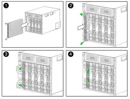
    FIGURE 2-1   Inserting the Disk Module Into the Chassis

    Figure showing insertion of the disk module
into the chassis


  5. Push the disk module into the slot until the disk module stops (see FIGURE 2-1 [2]).

  6. Rotate the ejectors down until they snap into place.

    The disk module should now be flush with the chassis (although the disk drives stick out about 1.5 mm) and the ejectors are locked (see FIGURE 2-1 [3, 4]).


The Sun Blade 6000 Disk Module Front Panel

The front panel of the Sun Blade 6000 Disk Module is shown in FIGURE 2-2.
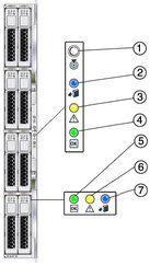
FIGURE 2-2   Sun Blade 6000 Disk Module Front Panel

Figure showing a front view of the disk module
with its LEDs


Refer to TABLE 2-1 for descriptions of the LED behavior.


TABLE 2-1   Front Panel LED Functions  
LED Name Description
1 Combined Locate button and LED (white) This LED helps you to identify which module you are working on in a chassis full of servers.
  • Push and release this button to make the Locate LED blink for 30 minutes.

  • When the Locate LED is blinking, push and release this button to make the Locate LED stop blinking.

  • Hold down the button for 5 seconds to initiate a “push-to-test” mode that illuminates all other LEDs for 15 seconds.

  • This LED can also be made to blink from a remote system using the CMM ILOM. Refer to the Sun Blade 6000 Disk Module Administration Guide for details.

2 Ready-to-Remove LED (blue)
  • Not used.

3 Module Fault LED (amber) This LED has two states:
  • On: An event has been acknowledged, and service action is required.

  • Off: Normal operation.

4 Module Activity LED (green) This LED has three states:
  • On: Module is configured and online.

  • Off: Module is not configured or is offline.

  • Blinking: Module is configuring or a firmware flash update is in progress.

5 Disk Drive Activity LED (green) This LED has three states:
  • On: Power is on and disk is online.

  • Off: Disk is offline.

  • Blinking: Irregular blinking means normal disk activity; steady, slow blink means RAID activity.

6 Disk Drive Fault and Locate LED (amber) This LED has four states:
  • On: Disk fault. Service action required.

  • Off: Normal operation.

  • Slow blink: Disk failure predicted.

  • Fast blink: Locate function activated.

7 Ready-to-Remove LED (blue)
  • Not used.