Sun Blade 6000 Disk Module
Service Manual 6000 Disk Module
Service Manual |
| C H A P T E R 2 |
This chapter contains information and procedures for servicing the Sun Blade 6000 disk module hardware, including component removal and replacement procedures.
On occasion, a disk drive might fail. The status of the drive is indicated by its LEDs, as shown in TABLE 2-1.
| LED Name | Description |
|---|---|
| HDD Activity LED (green) | This LED has three states: |
| HDD Fault and Locate LED (amber) | This LED has four states: |
| Ready-to-Remove LED (blue) |
A single disk failure does not cause a data failure when disks are configured as a mirrored RAID volume. When there is no hot spare assigned to the mirror, the failed disk can be hot-swapped. When the new disk is inserted, the contents are automatically rebuilt from the rest of the array with no need to reconfigure the RAID parameters.
If the mirror was configured with a hot spare, the mirror is automatically rebuilt with the hot spare.
Observe the amber Fault LEDs on the faces of the disks to identify the defective disk.
Execute the software commands appropriate to the software that you are using to prepare the hard drive for removal.
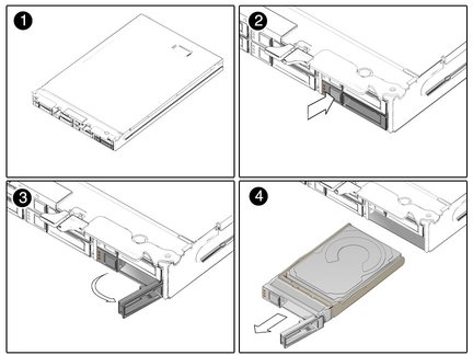
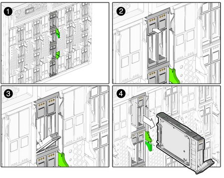
Press the button on the face of the disk to release the spring-loaded securing latch. See FIGURE 2-1 and FIGURE 2-2.
Grasp the securing latch and remove the disk from the drive bay.
Disks in the Sun Blade 6000 Disk Module are hot-pluggable, so you can remove a disk either when the disk module is installed in the chassis or when it is out of the chassis. See FIGURE 2-1 and FIGURE 2-2.


Copyright © 2009, Sun Microsystems, Inc. All rights reserved.