Introduction to the Sun Blade X6250 Server Module
|
This chapter contains overviews of the Sun Blade X6250 server module. It contains the following sections:
1.1 Features of the Servers
The Sun Blade X6250 server module is designed to fit into the Sun Blade 6000 chassis system. The Sun Blade X6250 server module supports two Intel Xeon 5000 series processors and embedded I/O that provides PCI-Express, SAS, and Gigabit Ethernet interfaces to the Sun Blade 6000 chassis midplane, and four SAS (with RAID Expansion Module) or SATA drive interfaces at the front of the server module. Server monitoring is performed by an onboard IPMI 2.0 compliant service processor with Integrated Lights Out Manager (ILOM) or an Embedded Lights Out Manager (ELOM).
TABLE 1-1 summarizes the features of the server module.
TABLE 1-1 Summary Comparison of Features
|
Feature or Component
|
Specifications
|
|
CPU
|
Up to two Intel Xeon 5000 series dual-core or quad-core processors
|
|
Memory
|
Up to 8 fully buffered ECC DIMMs per CPU (up to 64 GB capacity using 4 GB DIMMs)
|
|
Hard Disks (HDs)
|
Four Serial-Attached SCSI (SAS) or Serial ATA (SATA) HDs (2.5 inch) or four Solid State Drives (SSDs)
|
|
Service Processor
|
Onboard IPMI 2.0 compliant service processor (SP) with Intgrated Lights Out Manager or Embedded Lights Out Manager.
One 10/100 Management Ethernet Port to Midplane
Remote Keyboard/Video/Mouse (KVMS) over IP
|
|
RAID options
|
Four-channel SAS RAID disk controller
|
|
Midplane I/O
|
- Four 8-lane PCI-Express, one per Network Express Module (NEM)
- Two 10/100/1000 Gigabit Ethernet, one per NEM
- 10/100 Ethernet management port to the Chassis Control Module (CMM), which serves as the service processor for the Sun Blade 6000 chassis
|
|
Front Panel I/O
|
Dongle connector that interfaces to:
- VGA Graphics
- Serial Console to SP
- Dual USB ports (keyboard/mouse)
|
|
Compact Flash
|
IDE Compact Flash Module Interface
|
1.2 Sun Blade X6250 Server Module Orientation
This section contains illustrations that you can use to become familiar with the components of the Sun Blade X6250 server module.
1.2.1 Server Module Front Panel
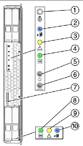
FIGURE 1-1 shows the features of the front panel.
FIGURE 1-1 Server Module Front Panel

Figure Legend
|
1
|
Locate button/indicator (white)
|
|
2
|
Ready to Remove indicator (blue)
|
|
3
|
Service Action Required / Fault (amber)
|
|
4
|
System Status Indicator (green)
|
|
5
|
Power on/standby button
|
|
6
|
For service use only
|
|
7
|
UCP (universal connector port) to connect dongle cable
|
|
8
|
HD OK/Activity Indicator (green)
|
|
9
|
HD Fault/Locate Indicator (amber)
|
|
10
|
HD Ready to Remove Indicator (blue)
|
1.2.2 Server Module Components
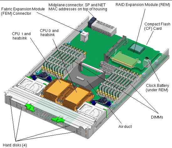
FIGURE 1-2 shows the locations of the server module replaceable components, with the top cover removed.
FIGURE 1-2 Server Module Replaceable Component Locations

1.3 Using a Dongle Cable for Testing
Your chassis ships with a dongle cable that allows you to plug devices directly into the front of the server.
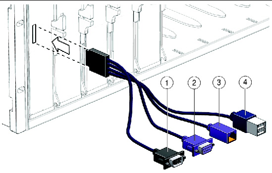
The dongle cable has either three of four connectors. FIGURE 1-3 shows a dongle with four connectors.
|
 To Use a Dongle Cable for Testing To Use a Dongle Cable for Testing
|
1. Insert the dongle cable into the universal connector port (UCP) on the server module front panel. See FIGURE 1-1 and FIGURE 1-3.
2. Connect the dongle cable connections as appropriate.
FIGURE 1-3 Dongle Cable Connections

Figure Legend
|
1
|
DB-9 serial connector
|
|
2
|
VGA video connector. Note: this connector is not present on a three-connector dongle
|
|
3
|
RJ-45 connector.
- On a three-connector dongle, this connector provides serial access to the service processor.
- On a four-connector dongle, this connector is unused.
|
|
4
|
Dual USB connectors
|

|
Caution - Disconnect the multi-port dongle cable when you are finished using the cable. Otherwise, the cable, blade, or chassis could be damaged when the chassis door is closed or the cable abruptly pulled.
|
TABLE 1-2 lists the pinouts of the DB9 port.
TABLE 1-2 DB9 Port Pinouts
|
Pin
|
Signal Description
|
Status
|
|
6
|
COM DSR
|
Not supported
|
|
2
|
COM SIN
|
Supported
|
|
7
|
COM RTS
|
Supported
|
|
3
|
COM SOUT
|
Supported
|
|
8
|
COM CTS
|
Supported
|
|
4
|
COM DTR
|
Supported
|
|
1
|
COM DCD
|
Supported
|
|
9
|
COM RI
|
Not supported
|

|
Caution - Disconnect the dongle cable when you are done with it. Otherwise, the cable could be damaged. Also, the server might exceed RFI specifications while the dongle is connected.
|
1.4 Accessory Kits
TABLE 1-3 lists the contents of the accessory kit that is shipped with the servers.
TABLE 1-3 Accessory Kit
|
Item
|
Part Number
|
|
Sun Blade X6250 Server Module Tools and Drivers CD
|
707-0093
|
|
Sun Blade X6250 Server Module Installation Guide
(printed documentation)
|
820-1182
|
|
Where to Find Sun Blade X6250 Server Module Documentation
(printed sheet)
|
820-1187
|
|
Additional safety and license documentation
|
|
1.5 Additional Options and Replaceable Components
Supported components and their part numbers are subject to change over time. For the most up-to-date list of replaceable components for these servers, go to:
http://sunsolve.sun.com/handbook_pub/Systems/
1. Click the name and model of your server.
2. On the product page that opens for the server, click on Full Components List for the list of components.
| Note - These servers are fully compliant with the Reduction of Hazardous Substances (RoHS) Directive.
|
1.6 Customer Replaceable Units (CRUs) and Field Replaceable Units (FRUs)
Customer Replaceable Units (CRUs) are designed to be changed by customers. Field Replaceable Units (FRUs) must be changed by Sun service personnel.

|
Caution - Changing FRUs can damage your equipment and void your warranty.
|
TABLE 1-4 lists the CRUs and FRUs.
TABLE 1-4 CRU and FRU List
|
Part
|
CRU or FRU
|
|
FRU, Blade, No CPU/Memory (motherboard)
|
FRU
|
|
CPU chip - quad core, 3.50 GHz, 1333 MHz (Xeon X5270)
|
FRU
|
|
CPU chip - quad core, 3.33 GHz, 1333 MHz (Xeon X5470)
|
FRU
|
|
CPU chip - quad core, 2.66 GHz, 1333 MHz (Xeon L5430)
|
FRU
|
|
CPU chip - quad core, 2.50 GHz, 1333 MHz (Xeon E5420)
|
FRU
|
|
CPU chip - quad-core, 1.86 GHz, 1066MHz (Xeon E5320)
|
FRU
|
|
CPU chip - quad-core, 1.60 GHz, 1066MHz (Xeon L5310)
|
FRU
|
|
CPU chip - quad-core, 2.33 Ghz, 1333MHz (Xeon E5345)
|
FRU
|
|
CPU chip - quad-core, 2.66 GHz, 1333MHz (Xeon X5355)
|
FRU
|
|
CPU chip - dual-core, 3.0 GHz, 1333 MHz (Xeon X5160)
|
FRU
|
|
CPU chip - quad-core, 3.0 GHz, 1333 MHz (Xeon X5365)
|
FRU
|
|
CPU chip - dual-core, 3.33 GHz, 1333 MHz (Xeon X5260)
|
FRU (see Note)
|
|
CPU chip - quad-core, 2.5 GHz, 1333 MHz (Xeon L5420)
|
FRU (see Note)
|
|
CPU chip - quad-core, 2.33 GHz, 1333 MHz (Xeon E5410)
|
FRU (see Note)
|
|
CPU chip - quad-core, 2.83 GHz, 1333 MHz (Xeon E5440)
|
FRU (see Note)
|
|
CPU chip - quad-core, 3.16 GHz, 1333 MHz (Xeon X5460)
|
FRU (see Note)
|
|
CPU chip - quad core, 3.00 GHz 1333 MHz (Xeon E5450)
|
FRU (see Note)
|
|
2 x 1 GB, DIMM kit
|
CRU
|
|
2 x 2 GB, DIMM kit
|
CRU
|
|
2 x 4 GB, DIMM kit
|
CRU
|
|
80 GB SFF SATA disk drive
|
CRU
|
|
73 GB 10K SFF SAS disk drive
|
CRU
|
|
73 GB 15K SFF SAS disk drive
|
CRU
|
|
146 GB SFF SAS disk drive
|
CRU
|
|
200 GB SFF SATA disk drive
|
CRU
|
|
300 GB 10K SFF SAS disk drive
|
CRU
|
|
Sun Blade RAID 5 Expansion Module (REM) (with or without battery)
|
CRU
|
|
Battery for Sun Blade RAID 5 Expansion Module
|
CRU
|
|
Sun Blade 10 GigabitEthernet Fabric Expansion Module (FEM)
|
CRU
|
|
PCIe Pass Through Fabric Expansion Module (FEM)
|
CRU
|
|
CR2032 coin battery
|
CRU
|
|
Cable kit
|
CRU
|
| Note - In servers with these CPUs, the Solaris 10 U4 OS requires patch 127112-05 or later, which must be added when the operating system is installed, as the server cannot boot without it. Servers with the Red Hat Linux must have RHEL 4.6 or newer.
|
| Sun Blade X6250 Server Module Service Manual
|
820-1185-17
|
   
|
Copyright © 2009 Sun Microsystems, Inc. All rights reserved.


