| Sun Blade X6450 Server Module Installation Guide |
| C H A P T E R 1 |
|
Introduction |
This chapter contains the following topics:
Note the following terms used in this book:
The following overview outlines the steps to install the server module. The actual procedures are in Chapter 2.
Unpack the server module before proceeding.
1. Insert the server module into the chassis.
When you are done, the server module comes up to standby mode. See Inserting the Server Module.
2. Access and configure the service processor. Using the service processor, you can:
When you are done, you can access the service processor from the Ethernet. You can also set the service processor’s network settings, including its IP address at this time.
3. Configure any additional network hardware. See Operating System Installation Options for more information.
4. Configure or select a boot device. See Accessing BIOS Configuration Utilities and Selecting a Boot Device for more information.
5. Install or configure your operating system.
This section describes how to apply standby power to the server module so you can operate the service processor. It also includes procedures for powering on and for shutting down the server module.
| Note - You can also power on and power off the server module remotely using the service processor. Powering on is described in Accessing the System Console. More complete instructions are provided in the corresponding service processor documentation. |
|
When standby power is applied, the service processor is powered on, and everything else is powered off.
If the chassis is powered on, standby power is automatically applied to the server module. No action is required.
|
1. Insert the server module into a powered chassis.
The server module comes up to standby power mode automatically.
In standby power mode, the green OK LED on the front panel flashes. The blue OK to Remove LED remains ON with ILOM 2.0 and ELOM. It remains Off with ILOM 3.0.
See FIGURE 1-1.
2. Use a non-conducting pointed object, such as a stylus, to press and release the recessed Power button on the server front panel.
When main power is applied to the full server, the green OK LED above the Power button lights and remains lit.
FIGURE 1-1 Server Module Front Panel

|
White LED - Locate. Use it to identify the server module. When turned on, the locate LED blinks at .25Hz for 30 minutes. To turn it on or off, press it momentarily, or use the ILOM as described in:
|
|
|
Blue LED - Ready to remove. Use ILOM 3.0 commands to turn it On and Off. |
|
|
Green LED - Power/OK. See LED Behavior for details. |
|
|
To power off the server, use one of the following two methods:
When main power is off, the Power/OK LED on the front panel begins flashing, indicating that the server is in standby power mode.
After you have shut down main power, it is OK to remove the server module from the chassis. You can use the ILOM 3.0 web interface or CLI to light the blue OK to Remove LED if necessary to inform onsite personnel that it is OK to remove it.

|
Caution - Do not remove the server module from the chassis while it is installing (flashing) firmware. |
| Note - To power off the server completely, you must remove it from the chassis, or disconnect the AC power cords from the back panel of the chassis. |
1. Log in to the ILOM web interface. See To Connect to the ILOM Web Interface for details.
2. Navigate to System Monitoring -> Indicators.
3. Select the radio button next to the Locate LED
4. Select an action from the drop-down menu:
|
|
1. Log in to the ILOM CLI. See To Connect to the ILOM CLI for details.
2. Use the following commands:
The Sun Blade X6450 can be configured to install the operating system in a wide variety of locations.
This section describes some of the options available. They include:
The following sections describe methods of configuring remote drives:
After you have configured one or more remote drives, you can proceed with the operating system installation. From the point of view of the operating system installation, when remote drives are installed and configured correctly, they operate the same as local drives. They should appear in the list when the operating system installation procedure queries for where to install the operating system.
If the operating system installation procedure requires you to select a boot device in the BIOS, see Accessing BIOS Configuration Utilities and Selecting a Boot Device.
The Sun Blade X6450 is equipped with a compact flash device that can support some operating systems. It is the only local option for installing an operating system.
The following operating systems support booting from compact flash:
The compact flash drive supports a finite number of writes before its performance degrades. You can mitigate the limited number of writes by configuring it to redirect the log files (the /var and /tmp directories) to another location. See your operating system documentation for details.
The SSD is a 32-gigabyte solid-state SATA drive that mounts on the motherboard.
| Note - This feature requires a F540-7821-01 or newer motherboard, with 2.0 software installed. The motherboard part number appears on the motherboard, and can be read using the service processor. |
When an SSD is present, it appears as a disk device which is controlled by the onboard SATA controller. You can install an operating system on it.
Note the following conditions:
For instructions to install an SSD, see the Sun Blade X6450 Server Module Service Manual.
The SAS-NEM module, mounted in the back of the chassis, allows to the Sun Blade X6450 Server Module to connect to SAS devices inside the chassis and outside of the chassis. Each chassis can support one or two SAS-NEM modules.
These configurations require the Sun Blade X6450 Server Module to have either a REM or a FEM.
The Sun Blade 6000 Disk Module and the Sun Blade X6450 Server Module work in pairs, with the server module in an even-numbered slot, directly to the left of the disk module. Thus, the pairs can be in slots 0+1, 2+3, 4+5, 6+7, or 8+9.
In this configuration, the eight disks on the disk module are available to the server module, and appear in the boot list as local drives.
For more information, see the Sun Blade 6000 Disk Module Installation Guide (820-1702), and the documentation for the corresponding SAS NEM module.
The following device requires software 3.0 or newer.
The following devices require software 2.0 or newer.
The following devices require a F540-7821-01 or newer motherboard, with 2.0 software installed. The motherboard part number appears on the motherboard, and can be read using the service processor.
The combinations, and the configurations they support appear in TABLE 1-1.
|
Sun Blade RAID 5 Expansion Module, or
|
||
|
Sun Blade RAID 5 Expansion Module, or
|
||
|
Sun Blade RAID 5 Expansion Module, or
|
Sun Blade 6000 10GbE Multi-Fabric Network Express Module Note - This SAS-NEM also supports the 10GbE Ethernet connectors. See External Connecton to the 10 GbE Ethernet Connections. |
FIGURE 1-2 shows a Sun Blade X6450 server module in slot 0 and a Sun Blade 6000 Disk Module in slot 1, with a pair of Sun Blade 6000 10GbE Multi-Fabric Network Express Modules.
FIGURE 1-2 Connections to a SAS NEM Module
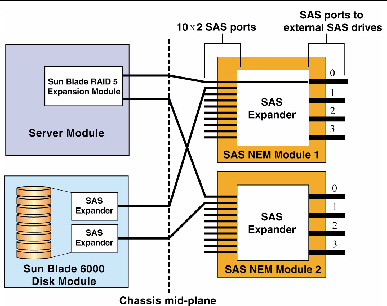
Inside the chassis, the Sun Blade 6000 Disk Module provides eight SAS drives.
The Sun Blade 6000 Disk Module and the Sun Blade X6450 Server Module work in pairs, with the server module in an even-numbered slot, directly to the left of the disk module. Thus, the pairs can be in slots 0+1, 2+3, 4+5, 6+7, or 8+9.
In this configuration, the eight disks on the disk module are available to the server module, and appear in the boot list as local drives.
In addition to the four external SAS connectors, the Sun Blade 6000 10GbE Multi-Fabric Network Express Module provides ten 10GbE ports. To use the 10GbE ports, you must have a Sun Blade 6000 10GbE Multi-Fabric Network Express Module installed.
For more information, see the Sun Blade 6000 Disk Module Installation Guide, and the documentation for the SAS NEM module.
The Sun Blade X6450 supports connections to an external SAN over a fibre channel link provided by a PCIe ExpressModule card in the corresponding PCIe ExpressModule slot. The PCIe ExpressModule card provides a fibre channel connection to the external SAN.
FIGURE 1-3 shows the configuration.
FIGURE 1-3 PCIe ExpressModule with Fibre Channel and SAN

The chassis supports two PCIe ExpressModule slots for each server slot. They are numbered N-0 and N-1, where N is the server slot number. The numbering is described in the chassis documentation.
See the documentation provided with the PCIe ExpressModule card for more details.
To configure a boot device on the SAN device, see Accessing BIOS Configuration Utilities and Selecting a Boot Device.
This section provides an overview of the boot process.
When you start your server module, it offers two chances to select the way it boots:
When you power on your server module, it completes its self-test and then displays a series of messages that offer a chance to access and configure the BIOS.
See the Sun Blade X6450 Server Service Manual for details.
| Note - Many configurations require you to configure your option card(s) with their respective BIOS configuration utilities before installing your operating system. See Accessing BIOS Configuration Utilities and Selecting a Boot Device for additional instructions. |
When the BIOS Power-On Self Test (POST) is finished, an operating system boots.
Most operating systems start by opening a bootloader. Like the BIOS, a bootloader offers a menu of boot selections, and if you do nothing, it boots the default selection. However, unlike the BIOS, the bootloader offers a choice of installed operating systems, not a selection of bootable hardware devices.
After you make a selection or accept the default, the bootloader boots the indicated selection.
Bootloaders are commonly used for two types of selections:
| Note - This is the currently supported method of switching the console output between the serial management port and the VGA port. |
After the bootloader exits, the server module continues to boot from the selection you have made.
The bootloader you see depends on the type of operating system booted by the BIOS:
For example, in a system with the Solaris operating system and the Windows operating system, if the BIOS boots the device containing the Solaris operating system, the GRUB bootloader appears. However, the GRUB can be configured to include a selection that boots a Windows operating system.
| Note - Bootloaders are highly configurable. The choices are determined by local configuration. See your network administrator for additional information. |
When the GRUB bootloader opens, it displays a menu of selections.
The Windows bootloader performs the same basic function as GRUB. For more details, see your Windows operating system documentation.
Because the Sun Blade X6450 is a diskless server, it most likely requires an option card to connect to its hard drives. In most cases, the option card must be configured using the BIOS configuration utility before you can install an operating system.
TABLE 1-2 lists some of the option cards and the keystrokes that access the corresponding BIOS configuration utility.
|
See the documentation that came with your PCIe ExpressModule. |
||
|
See the documentation that came with your PCIe ExpressModule. |
||
The following sections provide details for accessing BIOS configuration utilities.
1. Power on the server module.
2. Press F2 to access the BIOS.
4. Select the Boot Device Priority option.
5. Select a boot device from the menu.
Promote it to the top of the list by pressing + or - until it is at the top of the list.
1. Power on the server module.
2. Use Ctrl-Q to open the QLogic BIOS configuration utility.
3. Navigate to the Boot Device page.
The page displays a list of all bootable HDDs.
4. Enable the PCIe ExpressModule as a boot device.
See the documentation for your PCIe ExpressModule for details.
When you boot the system, the BIOS lists drives connected to the PCIe ExpressModule and allow you to select them as the boot drive.
5. (Optional) Configure volumes and RAID arrays as required.
See the documentation for your PCIe ExpressModule for details.
|
|
1. Power on the server module.
2. Use Ctrl-E to open the Emulex BIOS configuration utility.
3. Navigate to the Boot Device page.
The page displays a list of all bootable HDDs.
4. Enable the PCIe ExpressModule as a boot device.
See the documentation for your PCIe ExpressModule for details.
When you boot the system, the BIOS will list drives connected to the PCIe ExpressModule and allow you to select them as the boot drive.
5. (Optional) Configure volumes and RAID arrays as required.
See the documentation for your PCIe ExpressModule for details.
Selecting F12 during POST causes the server module to boot from the network, using a process called netboot.
When the netboot environment is properly configured, and the server module comes up, it broadcasts its IP address to the network, which responds by installing an operating system for it.
See your operating system documentation for information about netbooting.
RAID configuration requires an (optional) RAID Expansion Module (REM).
|
|
Caution - If you are going to include your boot drive in a RAID array, you must configure it before installing the operating system. Use one of the BIOS configuration utilities described in BIOS and BIOS Configuration Utilities. |
See To Configure the Sun Blade RAID 5 Expansion Module.
1. Power on the server module.
2. Use Ctrl-A to open the configuration utility.
3. Use the utility to create a volume for each disk or each RAID that you want the server’s BIOS (and OS if installed) to see.
The BIOS utility can create up to 20 volumes. Each volume can contain a single disk or a RAID (RAID levels 0, 1, 1E, 10, 5, or 6) with global or dedicated hot spares.
Each volume created by the BIOS Utility will be seen by the server’s BIOS as a single disk drive.
For additional information, see: the Sun Intel Adaptec RAID User's Guide.
1. Power on the server module.
2. Use Ctrl-C to open the configuration utility.
3. Follow the on-screen instructions to create a mirrored RAID.
You can choose between RAID 1 (two mirrored disks with an optional hot spare) or RAID 1E (three or more mirrored disks with one or two hot spares).
4. Exit the LSI RAID configuration utility.
5. You can install your OS on this RAID volume.
See the Sun LSI 106x RAID User’s Guide for additional configuration information.
After you have installed your server, you can install an operating system and drivers. Your server module supports the Solaris, Linux, VMware, or Windows operating systems.
The server module always sends console I/O to the VGA port.
By default, it sends service processor I/O to the serial port.
The External Serial Port control in the BIOS allows you to modify the behavior of the serial port connection.
These settings only affect the connections on the dongle cable.
| Note - You can also view console output using the service processor, as described in Accessing the System Console. |
| Sun Blade X6450 Server Module Installation Guide | 820-3535-13 |
Copyright © 2009 Sun Microsystems, Inc. All rights reserved.
 To Apply Standby Power