| C H A P T E R 2 |
|
Powering On the Server Module, Configuring BIOS and Resetting BIOS, SP and CMOS |
This chapter contains information about powering the server on and off, configuring the BIOS, resetting the BMC and BIOS passwords, clearing the CMOS password and updating firmware. Information about the (power-on self-test) POST and POST codes is also included.
The information is contained in the following sections:
This section contains procedures for powering on the server module.
| Note - Before powering on your server for the first time, follow the installation instructions provided in the Sun Blade X6450 Modular Server Installation Guide, (820-1182.) |
|
1. When you insert your server module into a chassis that is powered on, it comes up to standby power mode.
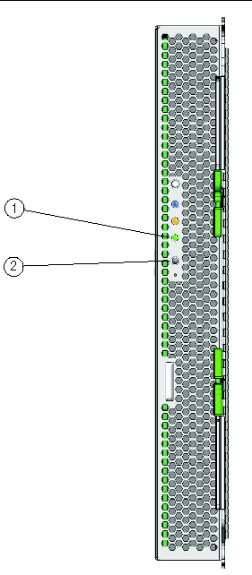
When the server module is in standby power mode, the green Power/OK LED on the front panel blinks, indicating that the service processor (SP) is working and the system is ready to be fully powered on to main power mode. See FIGURE 2-1 for the LED location.
| Note - See your chassis documentation for information about powering on the chassis. |
2. Use a non-conducting pointed object, such as a stylus to press and release the recessed Power button on the server front panel. See FIGURE 2-1 for the Power button location.
When main power is applied to the full server, the green Power/OK LED next to the Power button lights and remains lit.
FIGURE 2-1 shows the location of the power button.
You can also use the SP to turn on main power.
FIGURE 2-1 Power Button and Power/OK LED Location
You can use one of the methods for shutting down the server from main power mode to standby power mode.
1. Graceful shutdown: Use a non-conducting pointed object, such as a stylus to press and release the Power button on the front panel. This causes Advanced Configuration and Power Interface (ACPI) enabled operating systems to perform an orderly shutdown of the operating system. Servers not running ACPI-enabled operating systems will shut down to standby power mode immediately.
2. Emergency shutdown: Press and hold the Power button for four seconds to force main power off and enter standby power mode.
3. ELOM or ILOM web interface: Log in to the web interface and use the Remote Power Control screen to perform a graceful power off of the server.
4. ELOM or ILOM command-line interface (CLI): Log in to the ELOM or ILOM CLI and use the following command:
For more information about controlling server power from the web interface or CLI, see the corresponding SP documentation collection.
5. To completely power off the server, you must eject it from the chassis power connector or remove power from the chassis. See To Remove the Server Module From the Chassis or your chassis documentation for details.
| Note - When you use the Power button to enter standby power mode, the system continues to supply power to the SP and the power supply fans, and the Power/OK LED blinks. |
When main power is off, the Power/OK LED on the front panel blinks, indicating that the server is in standby power mode.
This section describes how to use the BIOS Setup Utility to view and modify the BIOS settings. The BIOS Setup Utility is stored in the BIOS memory. You access the BIOS Setup Utility by rebooting the server, watching the POST messages, and pressing F2 when prompted.
You can view the BIOS Setup Utility and configure the BIOS using several different interfaces:
The configured data is provided with context-sensitive Help. The data is stored in the system's battery-backed CMOS RAM. If the configuration stored in the CMOS RAM is invalid, the BIOS settings will default to optimal values.
To navigate the BIOS Setup Utility, use the left and right arrow keys to move sequentially back and forth through the screens. Fields that you can configure are highlighted or appear in color. Use the keyboard up and down arrow keys to scroll through a screen's submenu. Use the Tab key to move back and forth across columns.
|
1. Reboot the server, watch the display as the POST messages appear, and when prompted, press F2 to enter the BIOS Setup Utility.
The main BIOS Setup menu screen appears.
POST testing is indicated when the Power/OK LEDs on the front and back panels go into slow-blink mode.
2. Highlight the field to be modified using the arrow keys and Tab key.
3. Press Enter to select the field.
A dialog box appears. The dialog box presents you with the options available for the setup field that you have chosen.
4. Modify the setup field and close the screen.
5. If you need to modify other setup parameters, use the arrow keys and Tab key to navigate to the desired screen and menu item, then repeat Steps 1 through 4. Otherwise, go to Step 6.
6. Press and release the right arrow key until the Exit menu screen appears.
7. Follow the instructions on the Exit menu screen to save your changes and exit the Setup utility.
This section contains information and considerations regarding the system BIOS.
The slots for the PCIe ExpressModules are detected by the BIOS during startup in this order:
For example, if the server module is in slot 3, the BIOS boot priority will be 3.1, 3.0.
The Sun Blade X6450 server modules have up to two 10/100/1000BASE-T Gigabit Ethernet ports provided by the NEMs installed in the Sun Blade 6000 or 6048 chassis. The lower NEM port provides NET 0 and the upper NEM port provides NET 1. The numbers correspond to the slot number, as shown in FIGURE 2-2 (N represents the slot number).
FIGURE 2-2 Ethernet Port Chassis Labeling Designations
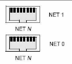
TABLE 2-1 shows how various operating systems and interfaces name the NICs shown in FIGURE 2-2.
The order in which the BIOS detects the Ethernet ports during boot, and the corresponding drivers that control those ports are listed below:
The BIOS Option ROM is 128 KB. Of these 128 KB, approximately 80 KB are used by the VGA controller, and the network interface card. Approximately 48 KB remain for the Option ROM.
| Note - Throughout this manual the terms BMC and SP are used interchangeably. The two terms are essentially the same and refer to the service processor. |
TABLE 2-2 provides summary descriptions of the seven top-level BIOS setup screens.
FIGURE 2-3 summarizes the BIOS Configuration Utility menu tree. See BIOS Setup Menu Screens for examples of each of these screens.
FIGURE 2-3 Server Module BIOS Configuration Utility Menu Tree
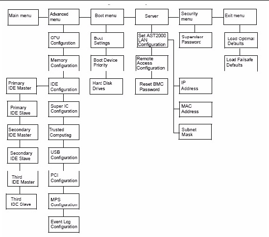
The following figures show sample BIOS setup menu screens. The screens shown are examples. The version numbers and the screen items and selections shown are subject to change over the life of the product.
The System Overview is the first screen that appears when you enter the BIOS Setup Utility. On this screen you can set the System Time and the System Date, and you can view server-specific BIOS and CPU information (see FIGURE 2-4).
FIGURE 2-4 BIOS Setup Menu Main Screen
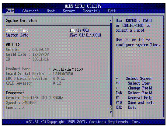
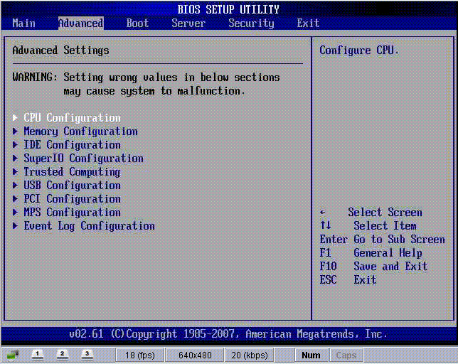
The Advanced Settings screen allows you to configure CPU, Memory, IDE, Super I/O, Trusted Computing, USB, PCI, MPS and Event Log settings (see FIGURE 2-5).
FIGURE 2-5 BIOS Setup Menu Advanced Screen
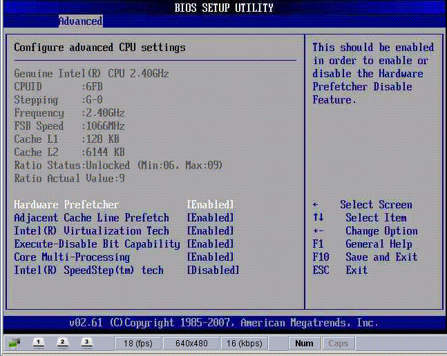
The Advanced/CPU Configuration screen allows you to view CPU-specific information and enable and disable various CPU functions (see FIGURE 2-6).
FIGURE 2-6 BIOS Setup Menu Advanced Configure CPU Screen
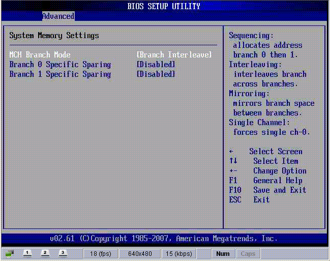
The Memory Configuration screen allows you to configure system memory settings (see FIGURE 2-7).
FIGURE 2-7 BIOS Setup Menu Advanced Memory Screen
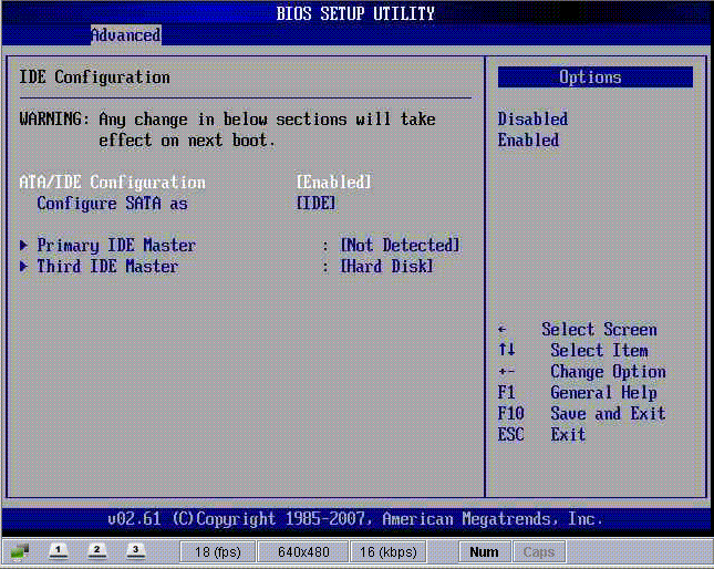
The IDE Configuration screen allows you to change the system’s IDE settings (see FIGURE 2-8). Changes made on this screen take effect on the next boot.
FIGURE 2-8 BIOS Setup Menu Advanced IDE Configuration Screen
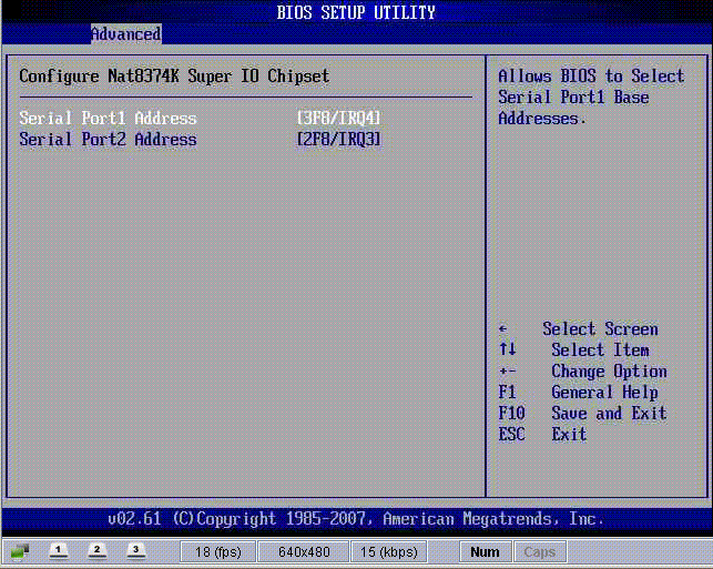
The Super I/O screen allows you to configure the Super I/O chipset. Use this screen to specify the address of serial port 1 and serial port 2 (see FIGURE 2-9).
FIGURE 2-9 BIOS Setup Menu Advanced Super I/O Screen
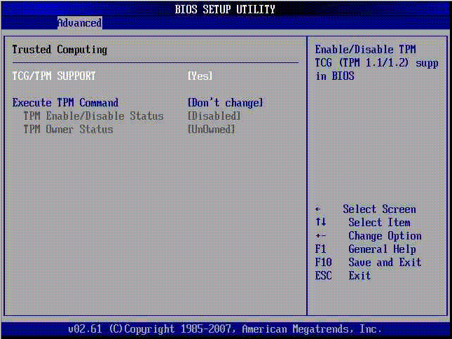
The Trusted Computing screen allows you to enable and configure TCG and TPM support (see FIGURE 2-10).
FIGURE 2-10 BIOS Setup Menu Advanced Trusted Computing Screen
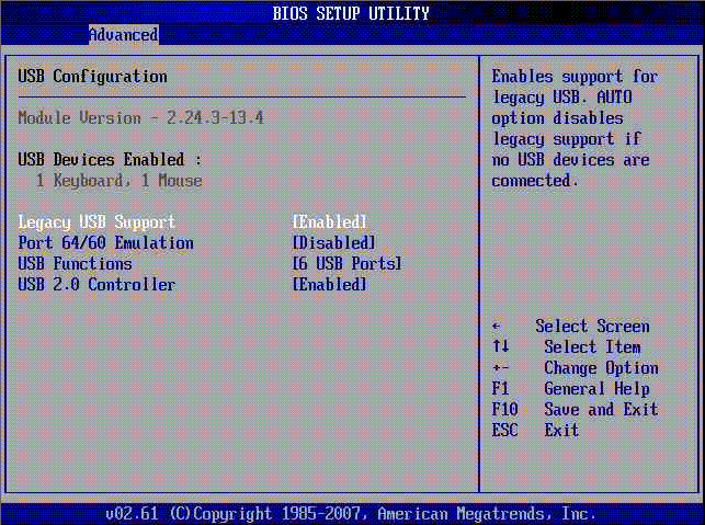
The USB Configuration screen allows you to view USB module version information and enable and configure USB devices (see FIGURE 2-11).
FIGURE 2-11 BIOS Setup Menu Advanced USB Configuration Screen
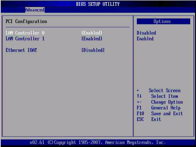
The PCI Configuration screen allows you to enable and disable the server’s LAN and Ethernet controllers (see FIGURE 2-12).
FIGURE 2-12 BIOS Setup Menu Advanced PCI Configuration Screen
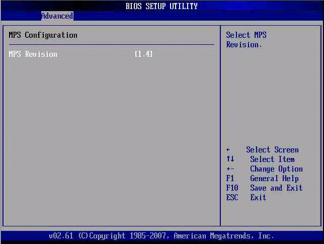
The MPS Configuration screen allows you to select the MPS revision (see FIGURE 2-13).
FIGURE 2-13 BIOS Setup Menu Advanced MPS Configuration Screen
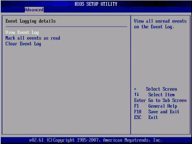
The Event Log Configuration screen allows you to view and clear the event log. You can also manage the log by marking messages (see FIGURE 2-14).
FIGURE 2-14 BIOS Setup Menu Advanced Event Logging Screen
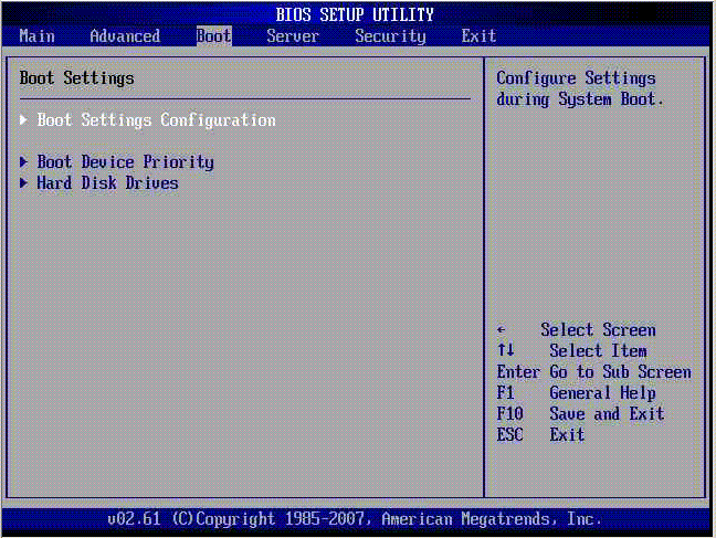
The Boot Menu allows you to access the Boot Settings submenu screens. The Boot Settings submenu screens allow you to configure system boot settings, boot device priority, and hard drives or the compact flash card (see FIGURE 2-15).
FIGURE 2-15 BIOS Setup Menu Boot Screen
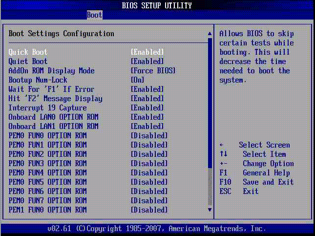
This submenu screen allows you to configure various boot settings, including quick or quiet boot, message display, and enable or disable PCIe ExpressModule (EM) functions (see FIGURE 2-16). For more information about the options presented in this screen, see Changing POST Options.
FIGURE 2-16 BIOS Setup Menu Boot Configuration Screen
The Boot Device Priority screen allows you to arrange your server’s boot device order. With this screen you can designate a primary boot device, as well as manage secondary boot devices (see FIGURE 2-17).
FIGURE 2-17 BIOS Setup Menu Boot Device Priority Screen
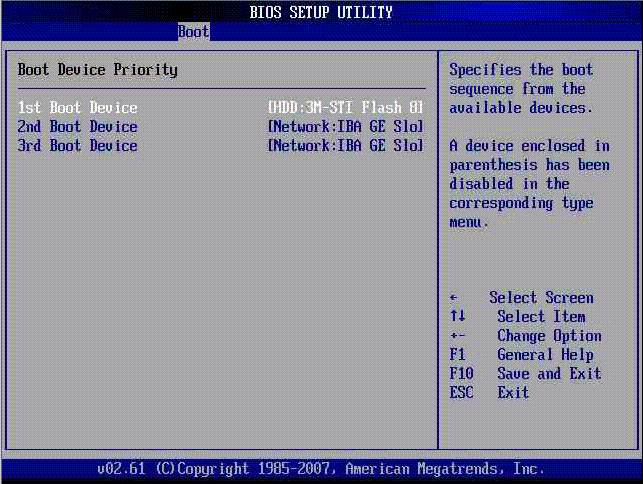
| Note - An installed NIC PCIe ExpressModule will allow you to see additional boot devices. |
The Boot Hard Disk Drives screen shows you the boot sequence of available hard drives. The Sun Blade X6450 server module is a diskless blade. However, when installed, the compact flash card and the SSD can appear as a boot drives in this screen (see FIGURE 2-18). Likewise, an installed NIC PCIe ExpressModule will allow you to see additional boot devices in the Boot Device Priority screen.
FIGURE 2-18 BIOS Setup Menu Boot Hard Disk Drives Screen
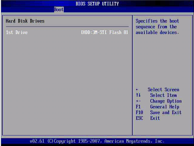
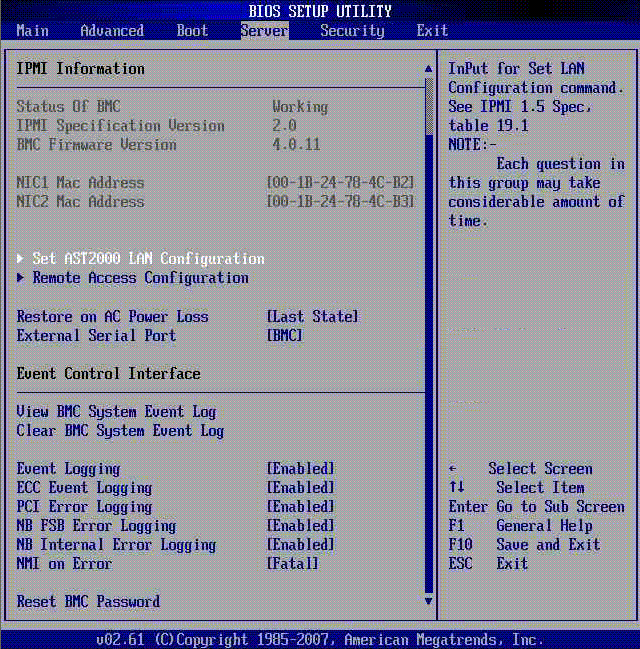
The Server screen allows you to verify the status of the BMC (SP), view version information for IPMI and BMC, view NIC MAC addresses, and configure AST2000 LAN and remote access settings. You can also configure AC power loss restoration, the external serial port, event logging, and you can reset the BMC password.
FIGURE 2-19 BIOS Setup Menu Server Screen
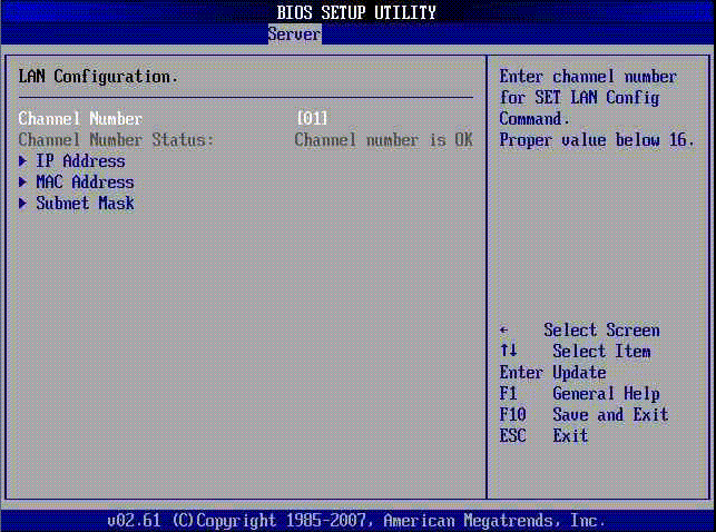
Use the LAN Configuration screen to configure the AST2000 LAN settings, such as channel number, IP address, MAC address, and subnet mask. You can also verify the channel number status.
FIGURE 2-20 BIOS Setup Menu Server LAN Configuration Screen
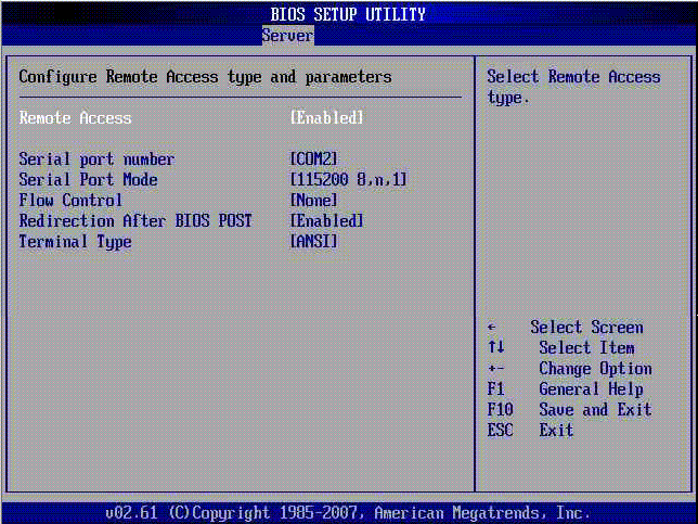
The Server Remote Access Configuration screen allows you to configure remote access type and parameters. For example, you can enable or disable remote access, set the serial port number and mode, flow control, redirection after POST, and terminal type.
FIGURE 2-21 BIOS Setup Menu Server Remote Access Configuration Screen
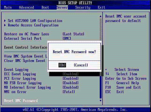
The Server Reset BMC Password option allows you to reset the password for the preconfigured default user account, root. This is the password that you use with the root user name to log in to both the web interface and the command-line interface (CLI). Use the Reset BMC Password option if you changed the root password and have lost or forgotten the password. When reset the password changes back to the default, changeme.
| Note - With ILOM 3.0 it is possible to delete the default user account, root. If it has been deleted, nothing changes when you select Reset BMC Password. |
| Tip - Use the web interface or the CLI to create a backup root account with administrator privileges. See the ILOM 3.0 documentation collection for details. |
FIGURE 2-22 BIOS Setup Menu Server Reset BMC Password Screen
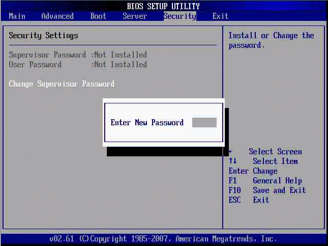
The Security Settings screen allows you to view the status of the Supervisor password. The screen also allows you to change the password (see FIGURE 2-23). When you change or create a password, the status indicator on this screen changes from Not Installed to Installed. The password provides security for the BIOS Setup Utility. When the password is installed, access to the BIOS Setup Utility is protected by the password.
| Note - To prevent unauthorized access to the BIOS Setup Utility, install and maintain the Supervisor password. |
FIGURE 2-23 BIOS Setup Menu Security Change Supervisor Password Screen
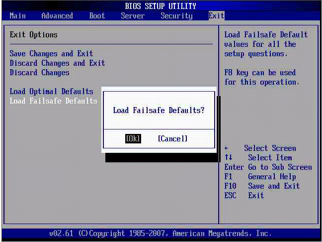
The Exit screen allows you to save any changes you made and exit the BIOS Setup Utility, discard changes and exit the utility, or discard changes and not exit the utility (see FIGURE 2-24). The Exit screen also allows you to load optimal defaults (see FIGURE 2-25) and load failsafe defaults (see FIGURE 2-26).
FIGURE 2-24 BIOS Setup Menu Exit Screen
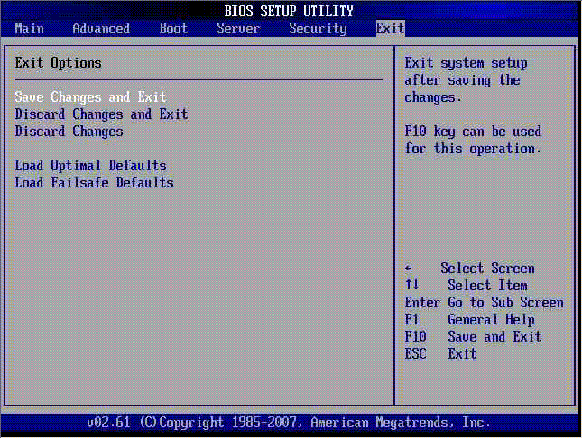
FIGURE 2-25 BIOS Setup Menu Exit Load Optimal Defaults Screen
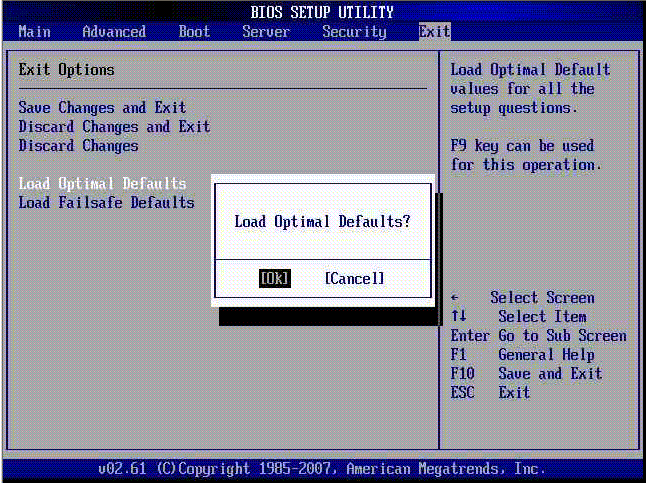
FIGURE 2-26 BIOS Setup Menu Exit Load Failsafe Defaults Screen
This section provides information about resetting the SP, BIOS, and CMOS passwords. You can use the BIOS Setup Utility to reset the SP password. To access the BIOS Setup Utility, you must setup the server with a keyboard, video, and mouse (KVM). You can attach a KVM to the server or use a remote KVM (RKVM).
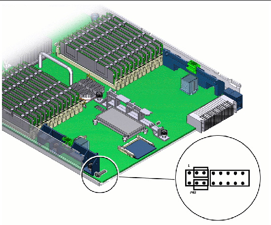
You need to use a hardware-based option to reset the BIOS password and clear the CMOS password. This option requires that you remove the server module from the chassis, access the motherboard, and use a jumper to short pins on jumper J42.
|
1. Set up the server module so that you can view POST messages and access the BIOS Setup Utility.
2. Reboot the server module, and watch the display for the prompt to press F2.
If you are using the ELOM’s Remote Console application, the server will boot directly into the BIOS Setup Utility, and you can skip to Step 4.
3. When prompted, press F2 to enter the BIOS Setup Utility.
The BIOS Setup Utility appears.
4. Use the arrow keys to navigate to the Server screen.
5. Use the down arrow key to highlight the Reset BMC Password option.
The Reset BMC Password Now? pop-up appears (see FIGURE 2-22).
7. Use the arrow keys to highlight OK, and press enter.
|
| Note - Clearing the CMOS password resets the BMC (SP) password. |
1. Place the server in standby power mode by using a non-conducting pointed object, such as a stylus, to press and release the recessed Power button on the front panel.
2. Remove the server module from the chassis. See To Remove the Server Module From the Chassis.
3. Remove the cover from the server. See To Remove the Main Cover.
4. Place the server module on an anti-static mat, and remove the top cover.
5. Put on the ESD wrist strap, and attach the grounding cord to the chassis’ bare metal or the chassis grounding post.
6. Locate jumper J42 on the motherboard.
J42 is located on the rear corner of the motherboard near the CF card slot. J42 is the 6-position jumper located to the left of a 10-pin jumper (see FIGURE 2-27).
FIGURE 2-27 Location of J42 on the Motherboard With Pin 1 Shown
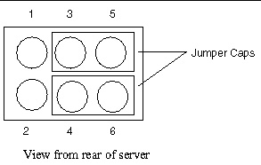
Two jumper caps are preinstalled on J42. The caps are set in the default or safe position.
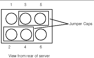
FIGURE 2-28 shows the pin numbering for jumper J42 and the jumper caps in the default or safe position:
FIGURE 2-28 Pinout for Jumper J42 and the Caps in the Safe Position
7. Change jumper caps on J42 as follows:
a. To clear the BIOS password, move the jumper cap from pins 4 and 6 to pins 2 and 4 (see FIGURE 2-29), and proceed to Step 8.
FIGURE 2-29 J42 With the Jumper Set to Reset the BIOS Password.
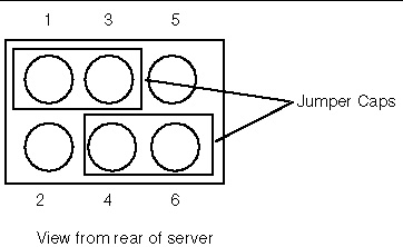
b. To clear the CMOS password, move the jumper cap from pins 3 and 5 to pins 1 and 3 (see FIGURE 2-30), and proceed to Step 8.
FIGURE 2-30 J42 With the Jumper Set to Clear the CMOS Password.
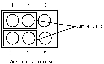
c. To reset the BIOS password and clear the CMOS password move the jumper cap from pins 4 and 6 to pins 2 and 4, and move the jumper from pins 3 and 5 to pins 1 and 3 (see FIGURE 2-31), and proceed to Step 8.
FIGURE 2-31 J42 With the Jumpers Set to Reset the BIOS Password and Clear the CMOS Password.
8. Install the server’s main cover.
9. Insert the server module into the chassis.
10. Return the server to full power mode by using a non-conducting pointed object, such as a stylus, to press and release the recessed Power button on the front panel.
To clear the CMOS and reset the passwords, you must allow the server to boot to full power. After POST you will see the message:
CMOS password cleared by jumper. |
This message indicates that the CMOS password was cleared. At this point the BIOS password is reset.
11. Repeat Step 1 through Step 10, and at Step 7 return the jumpers to the default or safe positions locations.
If the service processor (SP) software becomes corrupted, you can install the default image from the Tools and Drivers CD. For revision 1 motherboards, you need to remove the server from the chassis, and short the connections on jumper block J19 and J44 on the motherboard. For revision 2 motherboards, you might need to change the jumper cap position on jumper J51, in addition to shorting the connections on J19 and J44.
To perform this procedure, you have must have:
|
1. Determine the revision of your server module’s motherboard.
For information about how to determine the revision of your server module’s motherboard, see Identifying Sun Blade X6450 Server Module Revisions.
2. Copy all BMC files from the Tools and Drivers CD to a DOS-bootable USB flash device.
The BMC files are located in the /firmware/bmc directory, on the Tools and Drivers CD. They consist of:
3. Place the server in standby power mode by using a non-conducting pointed object, such as a stylus, to press and release the recessed Power button on the front panel.
4. Remove the server module from the chassis. See To Remove the Server Module From the Chassis.
5. Remove the cover from the server. See To Remove the Main Cover.
6. Place the server module on an anti-static mat, and remove the top cover.
7. Put on the ESD wrist strap, and attach the grounding cord to the chassis’ bare metal or the chassis grounding post.
8. If necessary, remove the optional Fabric Expansion Module (see Installing and Replacing a Fabric Expansion Module).
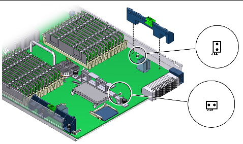
9. Use a jumper cap to short the pins on jumper block J19 and jumper block J44 (see FIGURE 2-32).
If your server is revision 1, go to Step 11.
FIGURE 2-32 Location of Jumpers J19 and J44 on the Motherboard.
10. If your server module is revision 2 and does not have low voltage DIMMs, move the jumper cap on J51 from pins 1 and 2 (default position) to pins 2 and 3 (see FIGURE 2-33).
Depending on the type DIMMs installed in your server module, the jumper cap might already set to pins 2 and 3.
FIGURE 2-33 The Location and Default Setting of J51
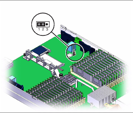
11. With the pins shorted on jumper block J19, J44, and pins 2 and 3 of J51 (revision 2 MB only), remove the wrist strap’s grounding cord from the chassis, and replace and secure the top cover.
12. Insert the server module into the chassis.
13. Insert the bootable USB flash drive into the USB port.
14. Power on the system by pressing the Power button.
| Note - You must press the power button to power on the server module. When the server module has jumpers installed, it does not automatically power on when inserted into the chassis. |
15. Press F8 to get a list of boot devices.
16. Set the USB flash device as the primary boot device, and save and exit.
The server module boots to DOS from the USB flash device, and a DOS prompt appears:
17. When the DOS prompt appears, run the following command, depending on whether your SP is ELOM-based or ILOM-based:
socflash SP binary backup file
Where SP binary is name of the firmware file.
Where backup file is the backup filename.
socflash x6450bmc.bin backup.bin
Where filename is the name of the ILOM .bin file.
> socflash -p1 -f ilom-X6450.bin
18. After a successful flash, remove the server module from the chassis, and remove the jumper caps from jumper blocks J19 and J44.
19. If necessary, move the jumper cap from pins 2 and 3 to pins 1 and 2 on jumper J51 (revision 2 only).
20. Insert the server module into the chassis, leaving the system powered off for at least 30 seconds.
The server module must be set up to view the BIOS Setup Utility.
21. Power on the system; watch the display, and when prompted, press F2 to enter the BIOS Setup Utility.
22. Verify the status of the BMC and the BMC version in the BIOS Setup Utility under the Server screen.
23. Exit the BIOS Setup Utility.
For information about BIOS POST testing, POST codes, POST code checkpoints, and console redirection, see Appendix B.
Copyright © 2009 Sun Microsystems, Inc. All rights reserved.