Tunneling and VPNs
Organizations typically have offices in more than one location. SunScreen EFS 3.0 provides a tunneling mechanism to let the different offices use public networks as a secure private network without needing dedicated lines and with no changes to user applications.
Note -
When editing multiple rules with ENCRYPT as the ACTION value, the tunnel address settings of the first rule you edit is copied into the next rule you edit. Use the command-line interface to modify the tunnel address settings of these rules.
When a tunnel, or virtual private network, is set up between two locations, all data packets traveling from one location to the other are encrypted and encapsulated inside other packets before they are sent over the public internetwork. Encrypting the packets guarantees that their contents will remain private; anyone capturing packets to snoop on network traffic between the two locations will be unable to read them. When the packets arrive at the remote location, they are decapsulated, decrypted, and forwarded to their intended destination.
In addition to protecting the privacy of network traffic, tunneling also lets a site conceal the details of its network topology from intruders or eavesdroppers. Because the original packets are encrypted, the source and destination addresses in their IP headers cannot be read. When the encrypted packets are encapsulated inside other packets, the new IP headers identify the addresses of the Screens that protect the locations, not the hosts that originated the packets. Consequently, the network topology behind the Screens is never exposed.
Note -
When using encryption with tunneling in 64-bit mode, the destination address is incorrectly translated. 32-bit machines are unaffected. To set a 64-bit installed machine to boot in 32-bit mode, go into firmware (the "ok" prompt) and set the boot file to kernel/unix, by typing: ok setenv boot-file kernel/unix.
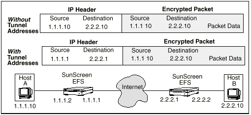
FIGURE 2-11 illustrates how tunneling affects the outside IP header of a packet traveling from Host A to Host B. Note that the encrypted packet containing the original data Host A sent to Host B is the same whether or not tunneling is used.
Figure 2-11 Effect of Tunneling on Contents of IP Headers

If you do not use a virtual private network (a tunnel) to transfer data between the two locations, the source and destination addresses on the outer IP header are the same as the source and destination addresses on the inner (encrypted) IP header: 1.1.1.10 and 2.2.2.10, respectively. Someone intercepting this packet would not be able to read its contents but could determine that hosts with IP addresses 1.1.1.10 and 2.2.2.10 reside behind the Screens protecting the two locations.
If you use a virtual private network to transfer data between the two locations, the Screen protecting Host A substitutes the IP address of its external interface (1.1.1.1) for the IP address of host A (1.1.1.10) in the Source Address field of the external IP header. Similarly, it substitutes the external IP address of the Screen at the other end of the tunnel (2.2.2.1) for the IP address of Host B in the Destination field. The local Screen then sends the packet through the nonsecure public network to the remote Screen.
When the remote Screen receives the packet, it strips off the encapsulation and decrypts the original packet from Host A. The remote Screen then reads the destination address from the original IP header of the decrypted packet and forwards the packet to Host B.
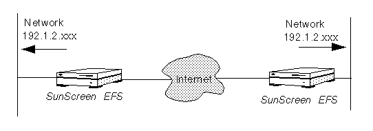
Note that, since the IP addresses behind the Screen are never exposed to hosts on the external Internet, the two locations do not need to assign externally valid IP addresses to hosts behind the Screens. As long as hosts behind the Screens do not need to communicate with hosts on the Internet, the two locations can use a shared IP address space, as shown in FIGURE 2-12.
Figure 2-12 Geographically Dispersed Network

- © 2010, Oracle Corporation and/or its affiliates
