Specific IPC Configuration
Remote IPC over Ethernet Data-link
To configure the remote IPC over Ethernet feature, set the IPC_REMOTE feature to true and the IPC_REMOTE_COMM feature to EXT (mentioned
in "IPC Feature Configuration"). In addition, switch on the IOM_IPC feature:
% configurator -set IOM_IPC=true |
This adds the Ethernet-specific module into the IOM component which acts as the IPC Ethernet data-link driver.
Once you have built and booted the ChorusOS system image on the target
board tgtbd1, the IPC Ethernet
data-link can be dynamically started. Use the built-in ethIpcStackAttach command of C_INIT (running on the target
board tgtbd1) :
% rsh tgtbd1 ethIpcStackAttach ethernet-device-name |
The ethernet-device-name argument is the
name of your Ethernet device with which your remote IPC
stack will communicate. This name is the full pathname of the Ethernet device
in the target device tree, displayed on the target system console by the system
at boot time. For example, a genesis2 board with
a dec21140 Ethernet controller connected through
a raven PCI bridge, has the pathname /raven/pci1011,9@e,0. This argument is only needed when the target
board has more than one Ethernet controller.
See the ethIpcStackAttach(1M) man page for more details.
The following example describes how to build a ChorusOS system image
for two similar PowerPC-based target boards, tgtbd1
and tgtbd2, each with an Ethernet controller. Site
numbers must be unique and statically configured in each ChorusOS system
image.
-
Configure Remote IPC over Ethernet, if not already configured:
% configurator -set IPC=true
% configurator -set IPC_REMOTE=true
% configurator -set IPC_REMOTE_COMM=EXT
% configurator -set IOM_IPC=true
-
Assign a site number to
tgtbd1, then build and uniquely identify the ChorusOS system image:
% configurator -set chorusSiteId=1
% make chorus
% mv chorus.RAM chorus.RAM.tgtbd1
Assign a site number to
tgtbd2, then build and uniquely identify the ChorusOS system image:
% configurator -set chorusSiteId=2
% make chorus
% mv chorus.RAM chorus.RAM.tgtbd2
-
Once you have booted the chorus.RAM.tgtbd1 system image on
tgtbd1and the chorus.RAM.tgtbd2 system image ontgtbd2, run the ethIpcStackAttach command:
% rsh tgtbd1 ethIpcStackAttach
% rsh tgtbd2 ethIpcStackAttach
Applications which need to communicate through remote IPC
can now be launched on the tgtbd1 and tgtbd2 targets.
Remote IPC over VME Bus
In current implementation of IPC over VME bus the following constraints must be satisfied:
-
The kernel must be configured for remote IPC feature over the VME bus (see "IPC Feature Configuration").
-
Each ChorusOS system image for every VME bus board must have the same logical and uniform view of all the devices present on the VME bus, through their respective device trees. As the device tree of each VME board will be different, a different ChorusOS archive should be built and booted on each target board. Typically, on
genesis2targets, the file src/bsp/powerpc/genesis2/ src/boot/deviceTree.c must be modified and recompiled for each different CPU board involved in the IPC protocol. -
IPC memory allocated to each CPU board must be in contiguous blocks of 64 Kilobytes on the VME bus.
-
The ChorusOS system image must be booted first on the VME bus system controller, and then on other (non-system controller) boards, in any order.
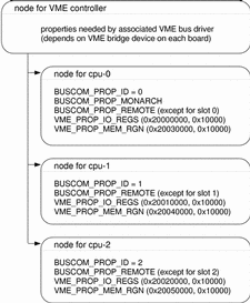
The following example describes what the device sub-tree representing the VME bus on each board should be. It assumes that your target consists of three VME boards in cage slots 0,1, and 2, your VME bus system controller is located in slot 0, 64Kb of memory is used on each board for IPC, and VME memory dedicated to IPC is allocated as follows:
Table A-1 VME memory dedicated to IPC|
bridge I/O registers |
IPC memory |
|
|---|---|---|
|
board 0: |
0x20000000-0x2000ffff |
0x20030000-0x2003ffff |
|
board 1: |
0x20010000-0x2001ffff |
0x20040000-0x2004ffff |
|
board 2: |
0x20020000-0x2002ffff |
0x20050000-0x2005ffff |
The device sub-tree representing the VME bus on each board is illustrated in Figure A-1.
Figure A-1 Device sub-tree representing the VME bus

The main differences between ChorusOS system images for each board are:
-
the properties associated with each VME bus controller device node
-
the presence of the BUSCOM_PROP_REMOTE property in each child node. This property selects which local or remote instance of the bus communication (
BUSCOM) VME device driver will be started on each node.
Building and booting ChorusOS system images on a VME
target system is similar to the one described in the previous example. Embedding
only the genesis2 targets in a system image is achieved
as follows:
- © 2010, Oracle Corporation and/or its affiliates
