| Sun IB Switch 9P Hardware Installation Guide |
| Sun IB Switch 9P Hardware Installation Guide |
|
Installing the Hardware |
This chapter describes how to mount the Sun IB switch into a rack and plug in the cables. This chapter contains the following sections:
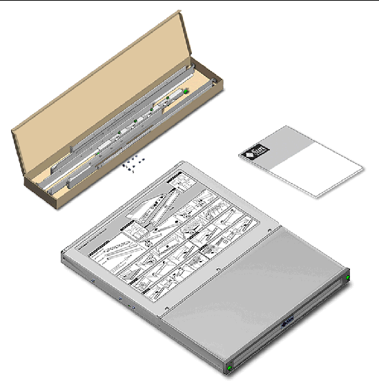
When you unpack your Sun IB switch, the box should contain the following items:
 IB Switch 9P Hardware Installation Guide
The Sun IB switch fits into any 19-inch rack. The rack rails can be adjusted to fit into a rack depth of 560mm (22.05") to 920mm (36.22"). These dimensions are from outside the front post to outside the rear post.
|
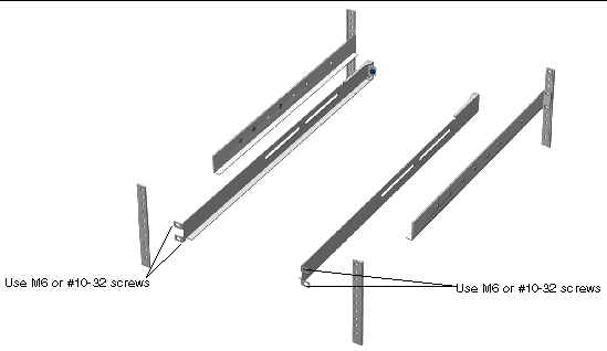
1. Attach the two pairs of rails to the rack.
a. Adjust the rear rail to the depth of the rack you're using and install it, using the two M6 or #10-32 screws on each side.
The illustration shows the rails being installed in a rack that requires separating the rails. For most racks, the rails can be adjusted to the correct depth by loosening the screws and expanding the rails to fit the rack.
b. Attach the left pair of rails, then the right pair, leaving rear screws loose so you can adjust the depth of the rails after you slide the switch onto the rails.
The rear ends of the rails have flanges that must overlap the back corners of switch to secure the back end of switch to the rails.
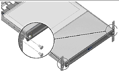
2. Slide the switch onto the rails.
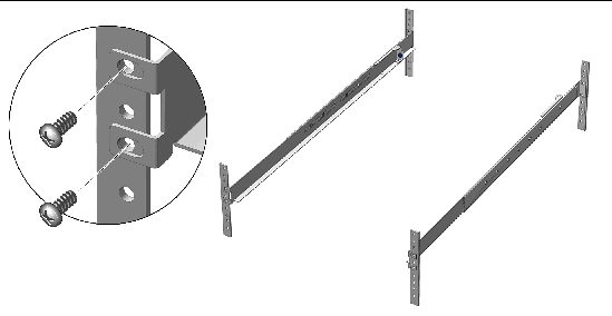
3. Mount the front to the rack, using two #10-32 or M6 screws to secure the front of the switch to the front rack rails.
The system rear is constrained by rack rails. Rack bracket tabs are printed black so they aren't so visible. Chassis tabs are silver so that you can differentiate which screw to remove, if you need to remove the switch from the rack
4. Slide the back ends of rack rails toward switch, so that rear rail flanges overlap switch rear corners. Tighten the rear rail screws to the rear rack posts.
5. Install the cable management bar to the rack rails, using captive screws on each side of the cable management bar.
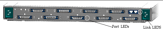
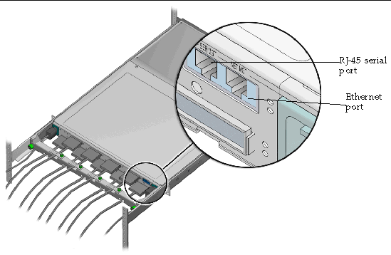
6. Identify the ports you want to connect to.
A single Sun InfiniBand switch can be connected to nine HCA ports with 12x-to-4x cable, to another switch with 12x-to-12x cable or a combination thereof. No pair of connected ports can belong to the same NodeGUID (that is, the same HCA instance).
|
Note - To the right of each port are two LEDs: one amber and one green. The amber LED lights only when the port requires attention. A steady light from the green LED shows that the link is up, blinking indicates InfiniBand activity. For more information about both port and link LEDs refer to the Sun |
7. Loosen the cable clamp release screw and pivot the clamp outward so you can plug in the cables, placing the cord into the slot in cable management bar.
8. Pivot the cable clamp back over the slot and tighten the captive screw.
9. Connect one end the RJ-45 serial cable to the serial port of the switch and the other end to the console you will use to manage the switch.
Your hardware installation is now complete.
|
Note - Refer to the Sun InfiniBand Switch Nine Port Administration Guide for instructions on how to configure and manage the Sun IB switch. You can download the administration guide from the following URL:
|
The power supply units are the only customer replaceable units (CRUs) in the switch.
|
1. Identify the power supply unit (PSU) you want to remove.
PSUs are identified as PS0 or PS1.
2. Access the ALOM command line interface (CLI).
You can access the ALOM CLI either through the serial port console or by telnet.
3. Issue a removefru command from the ALOM CLI:
The removefru command lights the blue Ready-to-Remove LED on the designated PSU, preventing confusion about which PSU to remove.
4. Unscrew the screws in the front panel.
5. Remove the front panel of the switch.
The switch contains two removable PSUs.
6. If the blue Ready-to-Remove LED is lit, pull out the PSU.
7. Press the latches toward the center of power supply and pull forward to remove it.
One power supply can be missing from the switch indefinitely without damage to the switch or loss of use.
|
Note - Without the second power supply unit, the switch has no failover function. |
|
1. Holding the PSU by the front edge, slide it into the slot.
2. Gently but firmly push the power supply into the switch until you hear it click into place.
3. Switch the power supply switch to on (|).
| Sun IB Switch 9P Hardware Installation Guide | 819-7246-10 |
Copyright © 2006, Sun Microsystems, Inc. All Rights Reserved.

 To Prepare the Switch for Rack Mounting