How to Install a StorEdge D1000 Disk Array
Use this procedure for an initial installation of a StorEdge D1000 disk array, prior to installing the Solaris operating environment and Sun Cluster software. Perform this procedure in conjunction with the procedures in the Sun Cluster 3.0 U1 Installation Guide and your server hardware manual.
Multihost storage in clusters uses the multi-initiator capability of the SCSI specification. For conceptual information on multi-initiator capability, see the Sun Cluster 3.0 U1 Concepts document.
-
Ensure that each device in the SCSI chain has a unique SCSI address.
The default SCSI address for host adapters is 7. Reserve SCSI address 7 for one host adapter in the SCSI chain. This procedure refers to the host adapter you choose for SCSI address 7 as the host adapter on the "second node."
To avoid conflicts, in Step 7 you change the scsi-initiator-id of the remaining host adapter in the SCSI chain to an available SCSI address. This procedure refers to the host adapter with an available SCSI address as the host adapter on the "first node." Depending on the device and configuration settings of the device, either SCSI address 6 or 8 is usually available.
Note -Even though a slot in the disk array might not be in use, do not set the scsi-initiator-id for the first node to the SCSI address for that disk slot. This precaution minimizes future complications if you install additional disk drives.
For more information, see the OpenBoot 3.x Command Reference Manual and the labels inside the storage device.
-
Install the host adapters in the node that you are connecting to the StorEdge D1000 disk array.
For the procedure on installing host adapters, see the documentation that shipped with your host adapters and node.
-
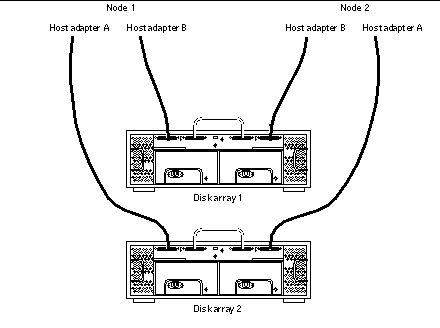
Connect the cables to the StorEdge D1000 disk arrays, as shown in Figure 5-1.
Make sure that the entire bus length that is connected to each StorEdge D1000 disk array is less than 25 m. This measurement includes the cables to both nodes, as well as the bus length internal to each StorEdge D1000 disk array, node, and the host adapter.
Figure 5-1 Example of a StorEdge D1000 Disk Array Mirrored Pair

-
Connect the AC power cord for each StorEdge D1000 disk array of the mirrored pair to a different power source.
-
Power on the first node and the StorEdge D1000 disk arrays.
For the procedure on powering on a StorEdge D1000 disk array, see the Sun StorEdge A1000 and D1000 Installation, Operations, and Service Manual.
-
Find the paths to the host adapters.
{0} ok show-disksIdentify and record the two controllers that are to be connected to the storage devices and record these paths. Use this information to change the SCSI addresses of these controllers in the nvramrc script in Step 7. Do not include the /sd directories in the device paths.
-
Edit the nvramrc script to change the scsi-initiator-id for the host adapters on the first node.
For a list of nvramrc editor and nvedit keystroke commands, see Appendix B, NVRAMRC Editor and NVEDIT Keystroke Commands.
The following example sets the scsi-initiator-id to 6. The OpenBoot PROM Monitor prints the line numbers (0:, 1:, and so on).
 Caution -
 Insert exactly one space after the first double quote and before scsi-initiator-id.
{0} ok nvedit 0: probe-all 1: cd /sbus@1f,0/QLGC,isp@3,10000 2: 6 encode-int " scsi-initiator-id" property 3: device-end 4: cd /sbus@1f,0/ 5: 6 encode-int " scsi-initiator-id" property 6: device-end 7: install-console 8: banner [Control C] {0} ok -
Store the changes.
The changes you make through the nvedit command are recorded on a temporary copy of the nvramrc script. You can continue to edit this copy without risk. After you complete your edits, save the changes. If you are not sure about the changes, discard them.
-
To store the changes, type:
{0} ok nvstore
{0} ok
-
To discard the changes, type:
{0} ok nvquit
{0} ok
-
-
Verify the contents of the nvramrc script you created in Step 7, as shown in the following example.
If the contents of the nvramrc script are incorrect, use the nvedit command to make corrections.
{0} ok printenv nvramrc nvramrc = probe-all cd /sbus@1f,0/QLGC,isp@3,10000 6 encode-int " scsi-initiator-id" property device-end cd /sbus@1f,0/ 6 encode-int " scsi-initiator-id" property device-end install-console banner {0} ok -
Instruct the OpenBoot PROM (OBP) Monitor to use the nvramrc script, as shown in the following example.
{0} ok setenv use-nvramrc? true use-nvramrc? = true {0} ok -
Power on the second node, but do not allow it to boot. If necessary, halt the system to continue with OBP Monitor tasks.
-
Verify that the scsi-initiator-id for each host adapter on the second node is set to 7.
Use the show-disks command to find the paths to the host adapters that are connected to these enclosures. Select each host adapter's device tree node, and display the node's properties to confirm that the scsi-initiator-id for each host adapter is set to 7.
{0} ok cd /sbus@1f,0/QLGC,isp@3,10000 {0} ok .properties scsi-initiator-id 00000007 differential isp-fcode 1.21 95/05/18 device_type scsi ... -
Continue with the Solaris operating environment, Sun Cluster software, and volume management software installation tasks.
For software installation procedures, see the Sun Cluster 3.0 U1 Installation Guide.
- © 2010, Oracle Corporation and/or its affiliates
