How to Add a Sun StorEdge T3 Disk Array
Use this procedure to add a new Sun StorEdge T3 disk array to a running cluster. This procedure provides flexibility so you can either add a Sun StorEdge T3 disk array, a Sun StorEdge FC-100 hub and host adapters, or add a Sun StorEdge T3 disk array to an existing Sun StorEdge FC-100 hub and host adapters.
This procedure defines Node A as the node you want to begin working with, and Node B as the remaining node.
-
Set up a Reverse Address Resolution Protocol (RARP) server on the network you want the new Sun StorEdge T3 disk array to reside on, and then assign an IP address to the new Sun StorEdge T3 disk array.
This RARP server enables you to assign an IP address to the new Sun StorEdge T3 disk array using the Sun StorEdge T3 disk array's unique MAC address.
For the procedure on setting up a RARP server, see the Sun StorEdge T3 Installation, Operation, and Service Manual.
-
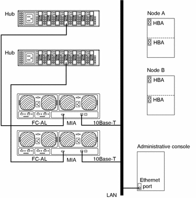
Install the media interface adapter (MIA) in the Sun StorEdge T3 disk array you want to add as shown in Figure B-2.
For the procedure on installing a media interface adapter (MIA), see the Sun StorEdge T3 Configuration Guide.
-
If necessary, install a gigabit interface converter (GBIC) in the Sun StorEdge FC-100 hub as shown in Figure B-2.
This GBIC allows you to connect the Sun StorEdge FC-100 hub to the Sun StorEdge T3 disk array you want to add.
Note -There are no hub port assignment restrictions. You can connect your Sun StorEdge T3 disk array and node to any hub port.
For the procedure on installing an FC-100 hub GBIC, see the FC-100 Hub Installation and Service Manual.
-
Install the 10Base-T Ethernet cable between the Sun StorEdge T3 disk array and the Local Area Network (LAN) as shown in Figure B-2.
-
Power on the Sun StorEdge T3 disk array.
Note -The Sun StorEdge T3 disk array might take a few minutes to boot.
For the procedure on powering on a Sun StorEdge T3 disk array, see the Sun StorEdge T3 Installation, Operation, and Service Manual.
-
Telnet to the Sun StorEdge T3 disk array you want to add, and, if necessary, install the required Sun StorEdge T3 disk array controller firmware.
Revision 1.16a firmware is required for the Sun StorEdge T3 disk array controller. For the procedure on upgrading firmware, see the firmware patch README.
-
Does this new Sun StorEdge T3 disk array have a unique target address?
-
If yes, proceed to Step 8.
-
If no, change the target address for this new Sun StorEdge T3 disk array.
For the procedure on verifying and assigning a target address, see the Sun StorEdge T3 Configuration Guide.
-
-
Install a fiber optic cable between the Sun StorEdge FC-100 hub and the Sun StorEdge T3 disk array as shown in Figure B-2.
Note -There are no hub port assignment restrictions. You can connect your Sun StorEdge T3 disk array and node to any hub port.
For the procedure on installing a fiber optic cable, see the Sun StorEdge T3 Configuration Guide.
Figure B-2 Adding a Sun StorEdge T3 disk array in a single-tray configuration

-
Configure the new Sun StorEdge T3 disk array.
For the procedure on creating a Sun StorEdge T3 disk tray logical volume, see the Sun StorEdge T3 Disk Tray Administrator's Guide.
-
Determine the resource groups and device groups running on Node A and Node B.
Record this information because you will use it in Step 42 of this procedure to return resource groups and device groups to these nodes.
# scstat
-
Move all resource groups and device groups off Node A.
# scswitch -S -h nodename
-
Do you need to install a host adapter in Node A?
-
Is the host adapter you want to install the first FC-100/S host adapter on Node A?
-
If no, skip to Step 15.
-
If yes, determine whether the Fibre Channel support packages are already installed on these nodes. This product requires the following packages.
# pkginfo | egrep Wlux
system 				SUNWluxd 					Sun Enterprise Network Array sf Device Driver
system 				SUNWluxdx					Sun Enterprise Network Array sf Device Driver (64-bit)
system 				SUNWluxl 					Sun Enterprise Network Array socal Device Driver
system 				SUNWluxlx 					Sun Enterprise Network Array socal Device Driver (64-bit)
system 				SUNWluxop 					Sun Enterprise Network Array firmware and utilities
-
-
Are the Fibre Channel support packages installed?
-
If yes, proceed to Step 15.
-
If no, install them.
The Sun StorEdge T3 disk array packages are located in the Product directory of the Solaris CD-ROM. Use the pkgadd command to add any necessary packages.
# pkgadd -d path_to_Solaris/Product Pkg1 Pkg2 Pkg3 ... PkgN
-
-
Stop the Sun Cluster software on Node A and shut down Node A.
# shutdown -y -g0 -i0
For the procedure on shutting down a node, see the Sun Cluster 3.0 System Administration Guide.
-
Power off Node A.
-
Install the host adapter in Node A.
For the procedure on installing a host adapter, see the documentation that shipped with your host adapter and node.
-
If necessary, power on and boot Node A.
{0} ok boot -xFor more information, see the Sun Cluster 3.0 System Administration Guide.
-
If necessary, upgrade the host adapter firmware on Node A.
For the required host adapter firmware patch, see the Sun StorEdge T3 Disk Tray Release Notes. For the procedure on applying the host adapter firmware patch, see the firmware patch README.
-
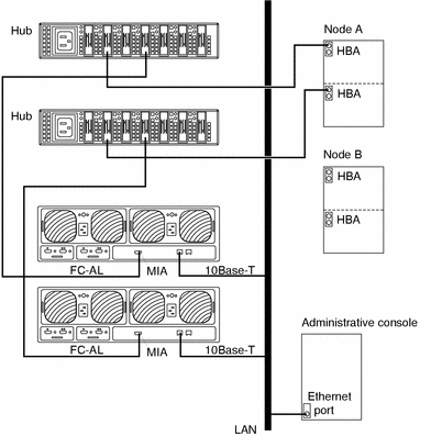
If necessary, install gigabit interface converters (GBIC) as shown in Figure B-3.
For the procedure on installing an FC-100 hub GBIC, see the FC-100 Hub Installation and Service Manual.
-
If necessary, connect a fiber optic cable between the Sun StorEdge FC-100 hub and Node A as shown in Figure B-3.
Note -There are no hub port assignment restrictions. You can connect your Sun StorEdge T3 disk array and node to any hub port.
For the procedure on installing a FC-100/S host adapter GBIC, see your host adapter documentation. For the procedure on installing a fiber optic cable, see the Sun StorEdge T3 Configuration Guide.
Figure B-3 Adding a Sun StorEdge T3 disk array in a single-tray configuration

-
If necessary, install the required Solaris patches for Sun StorEdge T3 disk array support on Node A.
For a list of required Solaris patches for Sun StorEdge T3 disk array support, see the Sun StorEdge T3 Disk Tray Release Notes.
-
Shut down Node A.
# shutdown -y -g0 -i0
-
Perform a reconfiguration boot to create the new Solaris device files and links on Node A.
{0} ok boot -r -
Label the new Sun StorEdge T3 disk tray logical volume.
For the procedure on labeling a Sun StorEdge T3 disk tray logical volume, see the Sun StorEdge T3 Disk Tray Administrator's Guide.
-
(Optional) On Node A, verify that the device IDs (DIDs) are assigned to the new Sun StorEdge T3 disk array.
# scdidadm -l
-
Do you need to install a host adapter in Node B?
-
Is the host adapter you want to install the first FC-100/S host adapter on Node B?
-
If no, skip to Step 30.
-
If yes, determine whether the Fibre Channel support packages are already installed on these nodes. This product requires the following packages.
# pkginfo | egrep Wlux
system 				SUNWluxd 					Sun Enterprise Network Array sf Device Driver
system 				SUNWluxdx					Sun Enterprise Network Array sf Device Driver (64-bit)
system 				SUNWluxl 					Sun Enterprise Network Array socal Device Driver
system 				SUNWluxlx 					Sun Enterprise Network Array socal Device Driver (64-bit)
system 				SUNWluxop 					Sun Enterprise Network Array firmware and utilities
-
-
Are the Fibre Channel support packages installed?
-
If yes, proceed to Step 30.
-
If no, install them.
The Sun StorEdge T3 disk array packages are located in the Product directory of the Solaris CD-ROM. Use the pkgadd command to add any necessary packages.
# pkgadd -d path_to_Solaris/Product Pkg1 Pkg2 Pkg3 ... PkgN
-
-
Move all resource groups and device groups off Node B.
# scswitch -S -h nodename
-
Stop the Sun Cluster software on Node B, and shut down the node.
# shutdown -y -g0 -i0
For the procedure on shutting down a node, see the Sun Cluster 3.0 System Administration Guide.
-
Power off Node B.
For more information, see the Sun Cluster 3.0 System Administration Guide.
-
Install the host adapter in Node B.
For the procedure on installing a host adapter, see the documentation that shipped with your host adapter and node.
-
If necessary, power on and boot Node B.
{0} ok boot -xFor more information, see the Sun Cluster 3.0 System Administration Guide.
-
If necessary, upgrade the host adapter firmware on Node B.
For the required host adapter firmware patch, see the Sun StorEdge T3 Disk Tray Release Notes. For the procedure on applying the host adapter firmware patch, see the firmware patch README.
-
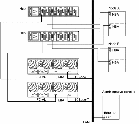
If necessary, install gigabit interface converters (GBIC) as shown in Figure B-4.
For the procedure on installing an FC-100 hub GBIC, see the FC-100 Hub Installation and Service Manual.
-
If necessary, connect a fiber optic cable between the Sun StorEdge FC-100 hub and Node B as shown in Figure B-4.
For the procedure on installing a FC-100/S host adapter GBIC, see your host adapter documentation. For the procedure on installing a fiber optic cable, see the Sun StorEdge T3 Configuration Guide.
Figure B-4 Adding a Sun StorEdge T3 disk array in a single-tray configuration

-
If necessary, install the required Solaris patches for Sun StorEdge T3 disk array support on Node B.
For a list of required Solaris patches for Sun StorEdge T3 disk array support, see the Sun StorEdge T3 Disk Tray Release Notes.
-
Shut down Node B.
# shutdown -y -g0 -i0
-
Perform a reconfiguration boot to create the new Solaris device files and links on Node B.
{0} ok boot -r -
(Optional) On Node B, verify that the device IDs (DIDs) are assigned to the new Sun StorEdge T3 disk array.
# scdidadm -l
-
Return the resource groups and device groups you identified in Step 10 to Node A and Node B.
# scswitch -z -g resource-group -h nodename
# scswitch -z -D device-group-name -h nodename
For more information, see the Sun Cluster 3.0 System Administration Guide.
-
Perform volume management administration to incorporate the new Sun StorEdge T3 disk tray logical volumes into the cluster.
For more information, see your Solstice DiskSuite or VERITAS Volume Manager documentation.
- © 2010, Oracle Corporation and/or its affiliates
