StorEdge A5200 Array SAN Considerations
This section contains information for using StorEdge A5200 arrays as the storage devices in a SAN that is in a Sun Cluster environment. StorEdge A5000 and A5100 arrays are not supported by the Sun SAN 3.0 release at this time.
Full, detailed hardware and software instructions for creating and maintaining a SAN are described in the Sun StorEdge Network FC Switch-8 and Switch-16 Installation and Configuration Guide, Sun SAN 3.0 that is shipped with your switch hardware. Use the cluster-specific procedures in this chapter for installing and maintaining StorEdge A5200 arrays in your cluster; refer to the Sun StorEdge Network FC Switch-8 and Switch-16 Installation and Configuration Guide, Sun SAN 3.0 for switch and SAN instructions and information on such topics as switch ports and zoning, and required software and firmware.
Hardware components of a SAN include Fibre Channel switches, Fibre Channel host adapters, and storage devices and enclosures. The software components include drivers bundled with the operating system, firmware for the switches, management tools for the switches and storage devices, volume managers, if needed, and other administration tools. Note that you must use two switches configured in parallel to achieve high-availability in a Sun Cluster environment.
StorEdge A5200 Array Supported SAN Features
Table 6-2 lists the SAN features that are supported with the StorEdge A5200 array. See the Sun StorEdge Network FC Switch-8 and Switch-16 Installation and Configuration Guide, Sun SAN 3.0 for details about these features.
Table 6-2 StorEdge A5200 Array Supported SAN Features|
Feature |
Supported |
|---|---|
|
Cascading |
No |
|
Zone type |
SL zone only |
|
Maximum number of arrays per SL zone |
3 |
|
Maximum initiators per SL zone |
2 |
|
Maximum initiators per array |
4 (2 per loop) |
|
Split loop support |
No |
Sample StorEdge A5200 Array SAN
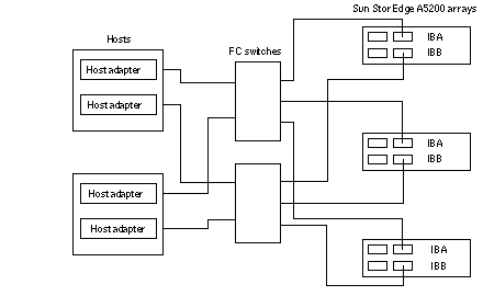
Figure 6-3 shows a sample SAN hardware configuration when using two hosts and three StorEdge A5200 arrays. Note that you must use two switches configured in parallel to achieve high-availability in a Sun Cluster environment. All switch ports are defined as the segmented loop (SL) type, as required. See the Sun StorEdge Network FC Switch-8 and Switch-16 Installation and Configuration Guide, Sun SAN 3.0 for details.
Figure 6-3 Sample StorEdge A5200 Array SAN Configuration

Additional StorEdge A5200 Array SAN Clustering Considerations
If you are replacing an FC switch and you intend to save the switch IP configuration for restoration to the replacement switch, do not connect the cables to the replacement switch until after you recall the Fabric configuration to the replacement switch. For more information about saving and recalling switch configurations see the Sun StorEdge Network FC Switch-8 and Switch-16 Installation and Configuration Guide, Sun SAN 3.0.
- © 2010, Oracle Corporation and/or its affiliates
