Appendix A Campus Clustering with Sun Cluster 3.0 Software - Concepts
This appendix introduces some of the basic concepts of campus clustering and provides some configuration and setup examples. It does not attempt to fully explain clustering, provide information on clustering administration, or to furnish details about hardware installation and configuration. For this information, see other Sun Cluster manuals, in particular the Sun Cluster 3.0 12/01 Concepts guide, the Sun Cluster 3.0 12/01 System Administration Guide, and the Sun Cluster 3.0 12/01 Hardware Guide, as well as manuals specifically referenced here.
Introduction
The only significant difference between traditional clustering and campus clustering is that of distance. In campus clustering, the nodes of a cluster configuration can be up to several kilometers apart. This increases the likelihood that, in the case of a catastrophe such as a fire or earthquake, at least one server and its storage will survive.
Sun Cluster software currently supports exactly two nodes in a campus cluster configuration. However, both two- and three-room configurations are supported. A room can be thought of as a functionally independent hardware grouping (such as a node and its attendant storage, or a quorum device physically separated from any nodes) that has been separated from other rooms to increase the likelihood of failover and redundancy in case of accident or failure. The definition of a room therefore depends on the type of failures to be safeguarded against, as indicated by Table A-1.
Table A-1 Definitions of "Room"|
Failure Scenario |
Sample Definitions of Separate Rooms |
|---|---|
|
Power line failure |
Isolated and independent power supplies |
|
Minor accidents, furniture collapse, seepage, etc. |
Different parts of physical room |
|
Small fire. Sprinklers (fire) starting |
Different physical area s (for example, sprinkler zone) |
|
Structural failure (building-wide fire, for example) |
Different buildings |
|
Large-scale natural disaster (for example, earthquake or flood) |
Different corporate campuses up to several kilometers apart |
Since all campus clusters are two-node clusters, each campus cluster must have a quorum disk. In two-room configurations, the quorum disk occupies the same room as one node (see "Example Two-Room Configuration"). In the case of a three-room configuration, the third room is used for the quorum disk ("Example Three-Room Configuration").
The node that first acquires a reservation on the quorum disk takes over cluster services; the other node is forced offline by means of a kernel panic. In a two-room configuration, the quorum disk should be located in the room that is more likely to survive an accident or catastrophe in the event that all cluster transport and disk connectivity is lost between rooms. (If only cluster transport is lost, the node sharing a room with the quorum disk will not necessarily be the room that reserves the quorum disk first.)
The advantage to a three-room cluster is that, if any one of the three rooms is lost, automatic failover should typically be possible; whereas with a two-room cluster, if an entire room is lost, automatic failover is possible only if the surviving room contains the quorum disk. Only a three-room configuration guarantees system availability in the event of complete loss of an entire room (in the absence of any other failures).
only -
As with non-campus configurations, data integrity will be compromised if there are other unrecovered I/O failures present when a room is destroyed, and the most up-to-date submirror was in the destroyed room.
In a campus cluster configuration, each of the two rooms used for nodes should have an equal number of shared disks. (In a two-room configuration, one room can have a separate quorum disk, so the two rooms need not have the same number of total disks.) Mirroring of the shared disks must always be done between rooms, rather than within rooms. In other words, both submirrors of a two-way mirror should never be in the same room. Mirroring is required for all campus cluster configurations, since RAID-5 alone does not lend itself to providing data redundancy across rooms.
If you use Solstice DiskSuite as your volume manager for shared device groups, pay special consideration to the distribution of replicas. In two-room configurations, all disksets should be configured with an additional replica in the room that houses the cluster quorum disk. Further, all Solstice DiskSuite device groups should be configured to use the node in the quorum disk room as their default primary room. In three-room configurations, the third room should not only house the quorum disk, but also include at least one extra disk configured into each of the disksets. Each diskset should include a third-room disk with an extra Solstice DiskSuite replica per diskset. Quorum disks can be used as metadb replicas in a metaset. Sun Cluster software does not currently support using the third room for data storage.
Sun Cluster software supports campus cluster configurations with rooms up to 10km apart.
Campus Cluster Configuration Examples
This section provides examples of two- and three-room campus clustering configurations:
-
Figure A-1 shows a two-room configuration using Sun StorEdge T3 partner groups.
-
Figure A-2 shows a three-room campus cluster using Sun StorEdge A5x00 disk arrays.
only -
The examples in this chapter illustrate general configurations and are not intended to indicate required or recommended setups. The type of storage device shown, for example, is purely for illustrative purposes. For simplicity's sake, the diagrams and explanations concentrate only on features unique to understanding campus clustering, so that, for example, public-network Ethernet connections are not shown.
See "Additional Campus Cluster Configuration Examples" for other example setups.
Example Two-Room Configuration
A two-room configuration is defined as follows:
-
Two separate rooms
-
Both rooms with one node each and disk subsystems
-
Data mirrored across disk subsystems in these rooms
-
At least one disk subsystem, attached to both hosts, used as a quorum device, located in one of the rooms
In the event of loss of the room containing the quorum disk, the system will be unable to recover automatically. Recovery will require operator intervention.
Figure A-1 shows a sample two-room configuration using a partner-group of Sun StorEdge T3/T3+ disk arrays in each room.
Figure A-1 Example Two-Room Campus Cluster
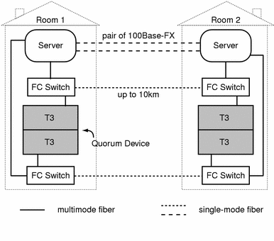
Figure A-1 is similar to a standard non-campus configuration; the most obvious difference is that Fibre Channel switches have been added to switch from multimode to single-mode fibers.
Although not so depicted in this chapter, campus clustering allows for configurations using multiple storage arrays. Where large storage environments are required, additional SAN switches for Sun StorEdge T3/T3+ arrays might be required.
Example Three-Room Configuration
A three-room configuration is defined as follows:
-
Three separate rooms
-
Two rooms with one node each and an equal number of disk arrays, in this case, Sun StorEdge A5x00 disk subsystems; data is mirrored across disk-subsystems in these rooms
-
Third room with at least one disk subsystem attached to both hosts to be used as a quorum device
Figure A-2 shows this configuration using Sun StorEdge A5x00 disk arrays. Note that, unlike Figure A-1, which used Sun StorEdge T3 disk trays, this configuration does not use Fibre Channel switches to connect Sun StorEdge A5x00 disk arrays. (Switches are not needed, as long-wave GBICs are already present in the A5x00s and should also be present in the servers' host bus adapters.)
Figure A-2 Example Three-Room Configuration
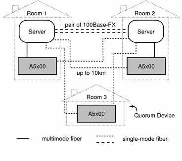
In this configuration, as long as at least two rooms are up and communicating, recovery will be automatic. This is the only configuration in which loss of any one room is guaranteed to be automatically handled. Loss of two rooms requires the replacement or rebuilding of one room and typically requires SunService intervention.
Requirements
This section provides an overview of requirements for campus clustering. For specific information on supported and required software and hardware, see the Sun Cluster 3.0 5/02 Release Notes and consult your Sun sales representative.
Software
Campus clusters require the following software:
-
Sun Cluster 3.0 Release 12/01 or later
-
Solaris 8
-
Volume management software (such as Solstice DiskSuite)
Servers
See the Sun Cluster 3.0 5/02 Release Notes or contact your sales representative for a list of Sun Cluster-certified servers.
Fibre Channel Switches, Fibers, and Host Adapters
Fibre Channel switches. Sun StorEdge T3/T3+ disk arrays do not connect directly to single-mode fiber, so a cluster using these devices requires Fibre Channel switches with long-wave GBICs installed in order to connect single-mode fibers to multimode fibers coming from disk arrays, hosts, and host bus adapters. (See Figure A-1.)
Storage fiber connections. For long-distance connections (up to 10km) between rooms, use 9/125-micron single-mode fiber.
When connecting Sun StorEdge T3/T3+ disk trays to Fibre Channel switches, use 50/125-micron multimode fibers at distances not exceeding 500m.
Host adapters. Connect Sun StorEdge A5x00 disk arrays using SOC+-based SBus host adapters.
With Sun StorEdge T3/T3+ disk trays, use a SAN-capable host adapter. Examples include the Sun StorEdge SBus Dual Fibre Channel Network Adapter, the Sun StorEdge PCI Single Fibre Channel Network Adapter, the Sun StorEdge PCI Dual Fibre Channel Network Adapter+, and the Sun StorEdge cPCI Dual Fibre Channel Network Adapter.
Storage Devices
Sun Cluster 3.0 supports campus clustering configurations using the Sun StorEdge A5x00 disk array or the Sun StorEdge T3/T3+ disk tray. The Sun StorEdge T3/T3+ can be configured either singly ("single-controller," as shown in Figure A-5) or in pairs ("partner-group," as shown in Figure A-1).
Long-wave gigabit interface converters (LWGBICs) should be used for the StorEdge A5x00 and Sun StorEdge T3/T3+ for distances greater than 500 meters and up to 10Km. (Use shortwave GBICs for distances less than 500 meters.) Consult Sun Professional Services for implementations with long-wave GBICs.
A campus cluster configuration must include two (or more) SANs for storage devices, in which the storage forming one submirror is in one room and mirrored to its submirror in another, physically separate room. Additionally, the submirrors of a mirror must be on different host bus adapters. For more on configuring SANs, refer to the Sun StorEdge Network FC Switch-8 and Switch-16 Installation and Configuration Guide, Sun SAN 3.0.
A quorum disk can be either a separate device or one of the dedicated storage devices (either Sun StorEdge T3/T3+ or A5x00).
only -
Because of potential limitations involving switch connectivity, it is not currently possible to use Sun StorEdge T3s in the third, quorum room.
Cluster Interconnect
The following components make up the campus cluster interconnect hardware configuration:
-
SunFastEthernet Adapter. The SunFastEthernet Adapter provides 10/100 Mbps Ethernet functionality with an RJ-45 connector.
-
Media converters. Use RJ-45 media converters to convert from copper to optical fiber connectors.
-
Two 9/125-micrometer single-mode fiber pairs.
Figure A-3 shows the setup for the cluster interconnect:
Figure A-3 100BASE-FX Setup

The interconnect should be capable of transmissions equal to the storage fiber connection distance. For connections up to 2km, multimode fibers can be used. If so, different transceivers might be required in place of media converters. Consult your sales representative.
Installing and Configuring Interconnect, Storage, and Fibre Channel Hardware
For the most part, using interconnect, storage, and fibre channel hardware does not differ markedly from non-campus cluster configurations.
-
The steps for installing Ethernet-based campus cluster interconnect hardware are very similar to those for non-campus clusters. Refer to the Sun Cluster 3.0 12/01 Hardware Guide for those steps.
When installing the media converters, consult the documentation that came with them, including requirements for fiber connections.
-
The steps for installing Sun StorEdge A5x00 and Sun StorEdge T3/T3+ arrays are very similar to those for non-campus clusters. Refer to the Sun Cluster 3.0 12/01 Hardware Guide for those steps.
However, when installing Sun StorEdge A5x00 arrays at distances greater than 500m, install the Sun Long Wave GBICs as indicated in the Sun StorEdge LW GBIC Service Manual. This manual also includes single-mode fiber specifications.
-
Campus clusters using Sun StorEdge T3/T3+ arrays require Sun Fibre Channel switches to mediate between multimode and single-mode fibers. The steps for configuring the settings on the Sun Fibre Channel switches are very similar to those for non-campus clusters.
Cascaded-switch SAN setups have requirements that are distinct from those of non-cascades setups, especially with regard to mirroring and zoning. Consult the Sun StorEdge Network FC Switch-8 and Switch-16 Installation and Configuration Guide, Sun SAN 3.0, as well as your service representative, for more information.
Additional Campus Cluster Configuration Examples
"Campus Cluster Configuration Examples" showed two possible configurations for campus clustering: a two-room configuration using Sun StorEdge T3 partner groups, and a three-room configuration using Sun StorEdge A5x00 arrays. While detailing all of the configurations possible in campus clustering is far beyond the scope of this document, the following illustrations depict some other variations on the setups previously shown.
The following are two-room examples:
-
Two-room campus cluster with Sun StorEdge T3/T3+ partner-groups and redundant switching (eight switches total) (Figure A-4)
-
Two-room campus cluster with Sun StorEdge T3/T3+ arrays, single-controller configuration (Figure A-5)
-
Two-room cluster using Sun StorEdge A5x00 disk arrays (Figure A-6)
The following are three-room examples:
-
Three-room campus cluster with Sun StorEdge T3/T3+ partner-group arrays (Figure A-7)
-
Three-room campus cluster with Sun StorEdge T3/T3+ single-controller arrays (Figure A-8)
-
Three-room cluster using Sun StorEdge A5x00 disk arrays (Figure A-9)
Two-Room Examples
Figure A-1 depicted a two-room campus cluster using Sun StorEdge T3 partner groups and four Fibre Channel switches. Figure A-4 shows the same setup with four additional switches for greater redundancy and potentially better I/O throughput.
Figure A-4 Two-Room Campus Cluster (T3 Partner-Groups, 8 Switches)
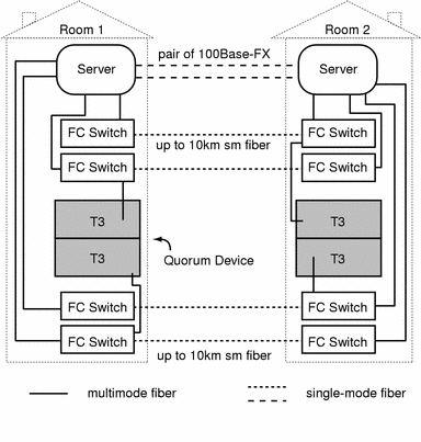
Figure A-5 is similar to Figure A-1, except that it uses Sun StorEdge T3/T3+ arrays in single-controller configurations, rather than partner-groups.
Figure A-5 Two-Room Campus Cluster (Sun StorEdge T3s, Single-Controller)
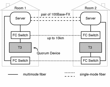
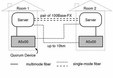
Figure A-6 depicts a two-room campus cluster using Sun StorEdge A5x00s. Note the absence of switches.
Figure A-6 Two-Room Configuration (Sun StorEdge A5x00s)
Three-Room Examples
The following examples all show three-room campus cluster configurations.
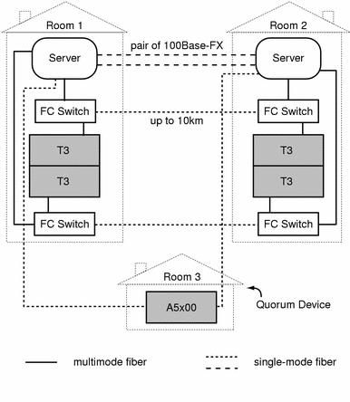
As mentioned in "Storage Devices", because of potential limitations with switch connectivity, Sun StorEdge T3/T3+ arrays cannot currently be used for the third, quorum room. Therefore, Figure A-7 and Figure A-8 show Sun StorEdge A5x00 disk arrays in the quorum room.
Figure A-7 is the same as Figure A-1, except that the quorum disk is separate and in a third room.
Figure A-7 Three-Room Campus Cluster (Sun StorEdge T3 Partner Groups)
Like Figure A-5, Figure A-8 uses Sun StorEdge T3/T3+ arrays in single-controller formation. However, in Figure A-8 the quorum disk is separate, in a third room.
Because the configurations in Figure A-7 and Figure A-8 use heterogeneous storage setups (Sun StorEdge T3/T3+ and Sun StorEdge A5x00 arrays), the host bus adapter types will be mixed. The Sun StorEdge A5x00 connects to the server using a SOC+-based SBus host adapter, so the server must be SBus-based, meaning that the connection to the T3/T3+ must also be SBus-based. Therefore, the T3 connection must be via a Sun StorEdge SBus Dual Fibre Channel Network Adapter.
Figure A-8 Three-Room Campus Cluster (Sun StorEdge T3 Single-Controller)
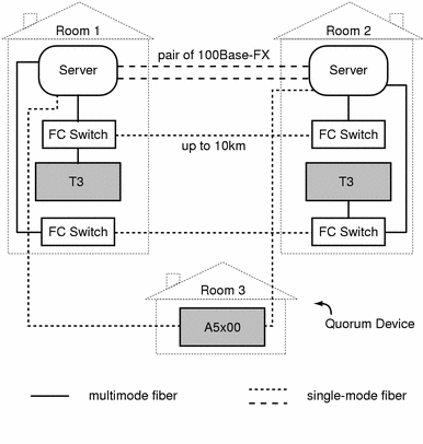
Figure A-9, like Figure A-6, depicts a campus cluster using Sun StorEdge A5x00 arrays; however, in Figure A-9, the quorum disk is now separate and in its own room.
Figure A-9 Three-Room Campus Cluster (Sun StorEdge A5x00s)

- © 2010, Oracle Corporation and/or its affiliates
