SCI Switch
General Hardware Inspection
Perform the following checks to determine the physical state of various SCI subsystem components. Verify that:
-
All SCI scrubber jumpers are properly set, depending on the cluster topology.
-
All SCI cables are properly seated.
-
All SCI switches have power applied
SCI Switch Status LED Locations
Clusters with three or four nodes can be connected through one or two SCI switches. The switch status LEDs provide information that can be used to troubleshoot SCI switch failures (Figure 6-1). Guidelines for interpreting these LEDs are provided in "Port Status LEDs"" and "General Switch Status LED".
Figure 6-1 SCI Status LED Locations

Port Status LEDs
The four port status LEDs located on the switch front panel can be used to troubleshoot individual port failures (Table 6-1).
Note -
A switch port sync error can result from a cable being removed.
Table 6-1 SCI Switch Port Status LEDs
|
Situation |
Port LED Status |
|---|---|
|
No power |
All four LEDs not lit |
|
Fatal switch errors: fatal hardware error, temperature to high, fan(s) not operative, power supply problem |
All four LEDs red |
|
Port errors: SCI cable out, sync error |
Associated port LED is red |
|
Port operative, no transactions |
Associated port LED is green |
|
Port operative, with transactions |
Associated port LED is blinking green |
General Switch Status LED
The switch status LED located on the rear panel indicates overall switch failures (Table 6-2).
Table 6-2 SCI Switch Rear Panel LED|
Situation |
LED Status |
|---|---|
|
Fatal switch errors: fatal hardware error, temperature too high, fan(s) not operative, power supply problem |
Red |
|
Switch operational |
Green |
The get_ci_status Command
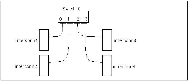
You can use the results of the get_ci_status command to troubleshoot clusters that have SCI switches. For example, for the configuration in Figure 6-2, if the get_ci_status command is used on interconn1, a typical output would be:
# /opt/SUNWsma/bin/get_ci_status sma: sci #0: sbus_slot# 1; adapter_id 8 (0x08); ip_address 1; switch_id# 0; port_id# 0; Adapter Status - UP; Link Status - UP sma: Switch_id# 0 sma: port_id# 1: host_name = interconn2; adapter_id = 72; active | operational sma: port_id# 2: host_name = interconn3; adapter_id = 136; active | operational sma: port_id# 3: host_name = interconn4; adapter_id = 200;inactive|inoperational # |
In this example, the line
sma: port_id# 3: host_name = interconn4; adapter_id = 200;inactive|inoperational |
indicates that the path between SCI switch 0, port 3 and interconn4 is inactive and not operational.
Figure 6-2 Typical Four-Node Configuration with an SCI Switch

In this instance, if the get_ci_status command were run on all four nodes, and if the same path was inactive and inoperative between SCI switch 0, port 3 and interconn4, it is more than likely that either the SCI switch 0, port 3, the cable, or the interconn4 host adapter is faulty.
However, if the get_ci_status command indicates that the same path is inactive and inoperative for one node only, such as in the instance of interconn1, then it is more than likely that either the interconn 1 host adapter, the cable, or SCI switch 0, port 0 is faulty.
Note that some aspects of the get_ci_status command output, such as host names, will vary according to your configuration.
Client Net Failure
System console messages will identify the specific port that has failed. Otherwise, for information on test commands as well as additional troubleshooting, refer to the documentation that came with your client network interface card.
- © 2010, Oracle Corporation and/or its affiliates
