PFS Basics
PFS file systems are defined in the hpc.conf file. There, each file system is given a name and the list of hostnames of the PFS I/O servers across which it will be distributed.
A PFS I/O server is simply a Sun HPC node that has disk storage systems attached, has been defined as a PFS I/O server in the hpc.conf file, and is running a PFS I/O daemon. A PFS I/O server and the disk storage device(s) attached to it are jointly referred to as a PFS storage system.
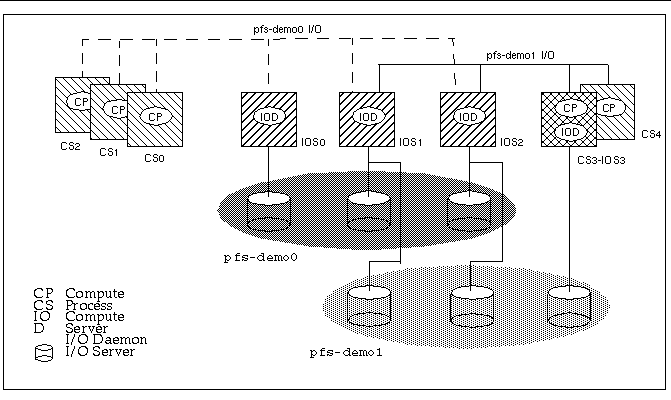
Figure 4-1 illustrates a sample Sun HPC cluster with eight nodes:
-
Four nodes function as compute servers only - CS0, 1, 2, and 4.
-
Three nodes functions as PFS I/O servers only - IOS0, IOS 1, and IOS2.
-
One node operates as both compute server and PFS I/O server - CS3-IOS3.
All four PFS I/O servers have disk storage subsystems attached. PFS I/O servers IOS0 and IOS3 each have a single disk storage unit, while IOS1 and IOS2 are each connected to two disk storage units.
The PFS configuration example in Figure 4-1 shows two PFS file systems, pfs-demo0 and pfs-demo1.
Each PFS file system is distributed across three PFS storage systems. This means an individual file in either file system will be divided into three blocks, which will be written to and read from its storage subsystems in three parallel data streams.
Note that two PFS storage systems, IOS1 and IOS2, contain at least two disk partitions, allowing them to be used by both pfs-demo0 and pfs-demo1.
Figure 4-1 PFS Conceptual View

The dashed lines labeled pfs-demo0 I/O indicate the data flow between compute processes 0, 1, and 2 and the PFS file system pfs-demo0. Likewise, the set of solid lines labeled pfs-demo1 I/O represent I/O for the PFS file system pfs-demo1.
This method of laying out PFS files introduces some file system configuration issues not encountered with UFS and other serial file systems. These issues are discussed in the balance of this section.
Note -
Although PFS files are distributed differently from UFS files, the same Solaris utilities can be used to manage them.
- © 2010, Oracle Corporation and/or its affiliates
