| Sun Management Center 3.5 Supplement for Sun Fire, Sun Blade and Netra Systems, 1.1
|
   
|
Physical and Logical Properties
|
The Sun Management Center console presents hardware information for the supported platforms using a common set of tables and fields. This chapter provides a summary of the classes and properties by table.
The chapter contains the following sections:
In the following tables, some fields can be filled with "--" or be blank in the following circumstances:
- The table or field is not currently used.
For example, for many physical components a serial number is not available and therefore the Serial Number field of the corresponding table will contain "--". This is also the case with other common properties.
- The field normally contains data under certain conditions.
For example, the Additional Info field contains textual information only when an alarm condition exists.
System Properties
The System Information table contains the top level view of the system hardware.
TABLE 3-1 System Information Table Properties
|
Property
|
Comments
|
|
Name
|
Fixed value of System
|
|
Machine
|
CPU architecture (for example, Sun4u)
|
|
Platform
|
Platform type
|
|
Total Disks
|
Total of all hard disks managed directly through the platform
|
|
Total Memory
|
Total of all DIMM memory capacity
|
|
Total Tape Devices
|
Total of all tape devices managed directly through the platform
|
|
Total Processors
|
Total number of CPU processors
|
|
Hostname
|
System IP hostname
|
|
Timestamp
|
Date and time that the Agent was started
|
|
OS Version
|
System OS version
|
|
OS Revision
|
OS revision
|
|
OBP Version
|
OBP Version
|
|
Module Status
|
Module Status
|
Physical Component Properties
The tables in this section represent instances of physical components within the system.
Common Properties
All physical components (apart from the Locations table) share a common set of properties:
- Name
- Location
- Description
- Model Name
- Operational Status
- Additional Information
- Part Number
- Version
- Serial Number
- Manufacturer
- Hot Swappable
- Removable
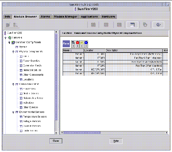
FIGURE 3-1 Physical Components Showing Location and Description Columns (Sun Fire V250 Shown)

The Operational Status property can take the values shown in TABLE 3-2.
TABLE 3-2 Operational Status Values
|
Property
|
Comments
|
|
OK
|
The component is operating normally.
|
|
Error
|
The component has a detected error.
|
|
Degraded
|
The component is providing service, but operating in a degraded state.
|
|
Unknown
|
The current operational status is unknown.
|
|
Failure Predicted
|
The component is functioning correctly but a failure in the near future is predicted.
|
|
Starting
|
The component is starting up but is not yet online.
|
|
Stopping
|
The component is shutting down.
|
|
Service
|
The component is being configured, maintained, cleaned, or otherwise administered.
|
|
Stressed
|
The component in operating but needs attention. Examples of stressed states include overloaded, overheated and so forth.
|
|
Non Recoverable
|
A nonrecoverable error has occurred.
|
|
No Contact
|
The current instance of the monitoring system has knowledge of this component but has never been able to establish communication with it.
|
|
Lost Comms
|
The component is known to exist and has been contacted successfully in the past, but is currently unreachable.
|
|
Stopped
|
The component is known to exist and has not failed, but is not operational and is unable to provide service to users. That is, the component has been purposely made non operational.
|
Fans
TABLE 3-3 Fan Table Properties
|
Property
|
Comments
|
|
Name
|
Unique name
|
|
Location
|
Path to the device location
|
|
Description
|
Informal component description
|
|
Model Name
|
Sun Microsystems model name
|
|
Operational Status
|
Current component state
|
|
Additional Info
|
Supporting textual information for the current Operational Status
|
|
Part Number
|
Sun Microsystems or other part number
|
|
Version
|
Part version number
|
|
Serial Number
|
Part serial number
|
|
Manufacturer
|
Vendor name
|
|
HotSwappable
|
Boolean: specifies in the component is hot swappable
|
|
Removable
|
Boolean: specifies if the component is removable
|
Power Supplies
TABLE 3-4 Power Supply Table Properties
|
Property
|
Comments
|
|
Name
|
Unique name
|
|
Location
|
Path to the device location
|
|
Description
|
Informal component description
|
|
Model Name
|
Sun Microsystems model
|
|
Operational Status
|
Current component status
|
|
Additional Info
|
Supporting textual information for the current Operational Status
|
|
Part Number
|
Sun Microsystems or other part number
|
|
Version
|
Part version number
|
|
Serial Number
|
Part serial number
|
|
Manufacturer
|
Vendor name
|
|
HotSwappable
|
Boolean: specifies in the component is hot swappable
|
|
Removable
|
Boolean: specifies if the component is removable
|
Expansion Cards
This table identifies other expansion cards that have been attached to the system.
TABLE 3-5 Expansion Card Table Properties
|
Property
|
Comments
|
|
Name
|
Unique name
|
|
Location
|
Path to the device location
|
|
Description
|
Informal component description
|
|
Model Name
|
Sun Microsystems model
|
|
Operational Status
|
Current component status
|
|
Additional Info
|
Supporting textual information for the current Operational Status
|
|
Part Number
|
Sun Microsystems or other part number
|
|
Version
|
Part version number
|
|
Serial Number
|
Part serial number
|
|
Manufacturer
|
Vendor name
|
|
HotSwappable
|
Boolean: specifies in the component is hot swappable
|
|
Removable
|
Boolean: specifies if the component is removable
|
|
Bus Type
|
Identifies card as PCI, cPCI, SCSI and so forth
|
The Expansion Card table contains rows corresponding to PCI cards that are installed in your system. The hardware platform module can present a textual description of the card together with the SunStore optional component code and Sun Microsystems part number in the Description, Model Name and Part Number fields, respectively.
Appendix A contains a list of cards for which this information is currently available. Additional cards will be added in subsequent updates of the software as they become available.
Cards for which the add-on software is not configured to provide this information, display the text "--" in the Description, Model Name and Part Number fields.
Memory Modules
This table identifies physical memory components such as DIMMs
TABLE 3-6 Memory Modules Table Properties
|
Property
|
Comments
|
|
Name
|
Unique name
|
|
Location
|
Path to the device location
|
|
Description
|
Informal component description
|
|
Model Name
|
Sun Microsystems model
|
|
Operational Status
|
Current component status
|
|
Additional Info
|
Supporting textual information for the current Operational Status
|
|
Part Number
|
Sun Microsystems or other part number
|
|
Version
|
Part version number
|
|
Serial Number
|
Part serial number
|
|
Manufacturer
|
Vendor name
|
|
HotSwappable
|
Boolean: specifies in the component is hot swappable
|
|
Removable
|
Boolean: specifies if the component is removable
|
|
Size
|
DIMM size
|
|
Blank Label
|
The physical label associated with this component
|
|
ECC Error Count
|
The number of ECC error counts recorded for this component
|
Other Physical Components
This table is used for all physical components other than those already listed.
TABLE 3-7 Other Physical Components Table Properties
|
Property
|
Comments
|
|
Name
|
Unique name
|
|
Location
|
Path to the device location
|
|
Description
|
Informal component description
|
|
Model Name
|
Sun Microsystems model
|
|
Operational Status
|
Current component status
|
|
Additional Info
|
Supporting textual information for the current Operational Status
|
|
Part Number
|
Sun Microsystems or other part number
|
|
Version
|
Part version number
|
|
Serial Number
|
Part serial number
|
|
Manufacturer
|
Vendor name
|
|
HotSwappable
|
Boolean: specifies in the component is hot swappable
|
|
Removable
|
Boolean: specifies if the component is removable
|
Locations
Locations represent slots into which components can be (hot) plugged.
TABLE 3-8 Other Physical Components Table Properties
|
Property
|
Comments
|
|
Name
|
Unique name
|
|
Location
|
Path to the device location
|
|
Location Type
|
Specifies the type of component occupying the location
|
|
Occupancy
|
Permitted values are unknown, occupied or empty
|
Logical Device Properties
Devices represent the logical devices. For example, a CPU module could contain one or more processors, hence the CPU module would be represented as a physical component, whereas the processors within it would be represented here as logical devices. The following tables enumerate the logical devices included in the common model.
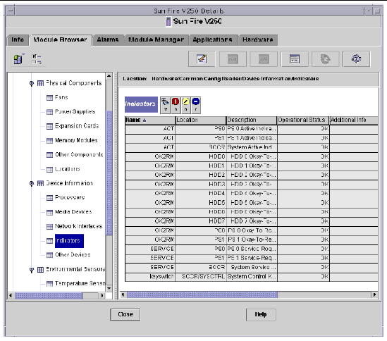
FIGURE 3-2 Part of the Logical Device Table Showing Indicators (Sun Fire V250 Shown)

Logical devices introduce an Availability property. The Availability values are:
- Other
- Unknown
- Running/Full Power
- Warning
- In Test
- Not Applicable
- Power Off
- Off Line
- Off Duty
- Degraded
- Not Installed
- Install Error
- Power Save - Unknown
- Power Save - Low Power Mode
- Power Save - Standby
- Power Cycle
- Power Save - Warning
- Paused
- Not Ready
- Not Configured
- Quiesced
Also introduced with logical devices is the Redundancy Status property. For devices that are part of a redundancy group, this indicates the current rôle played by this component. For example, a service processor may be operating in an active/standby pairing with another service processor. Similarly a network interface may be the primary or secondary member of a redundant network pair. Valid values for Redundancy Status are:
- Not Applicable
- Unknown
- Active
- Standby
- Primary
- Secondary
- Other
Processors
TABLE 3-9 Processor Table Properties
|
Property
|
Comments
|
|
Name
|
Unique name
|
|
Location
|
Path to the device location
|
|
Description
|
Informal device description
|
|
Operational Status
|
Current device status
|
|
Additional Info
|
Supporting textual information for the current Operational Status
|
|
Availability
|
The device availability
|
|
Redundancy Status
|
Device status as part of a redundancy group
|
|
Device ID
|
Numeric ID as used by various Solaris commands
|
|
Clock Frequency
|
Processor clock speed
|
|
Family
|
Processor family, for example, sparcv9
|
|
Data Cache Size
|
Primary data cache size
|
|
Instruction Cache Size
|
Primary instruction cache size
|
|
Level 2 Cache Size
|
Size of level 2 cache
|
Media Devices
This table represents all media devices: disks, CD-ROM, DVD-ROM, tapes, and so forth.
TABLE 3-10 Media Device Table Properties
|
Property
|
Comments
|
|
Name
|
Unique name
|
|
Location
|
Path to the device location
|
|
Description
|
Informal device description
|
|
Operational Status
|
Current device status
|
|
Additional Info
|
Supporting textual information for the current Operational Status
|
|
Availability
|
The device availability
|
|
Redundancy Status
|
Device status as part of a redundancy group
|
|
Physical Path
|
Media access device path under /dev/rdsk or /dev/rmt
|
|
Type
|
Disk, CD-ROM, DVD-ROM, Tape
|
|
Hard Error Count
|
The count of hard device errors, as available through iostat -e
|
|
Soft Error Count
|
As available through iostat -e
|
|
Transport Error Count
|
As available through iostat -e
|
Network Interfaces
TABLE 3-11 Network Interface Table Properties
|
Property
|
Comments
|
|
Name
|
Unique name
|
|
Location
|
Path to the device location
|
|
Description
|
Informal device description
|
|
Operational Status
|
Current device status
|
|
Additional Info
|
Supporting textual information for the current Operational Status
|
|
Availability
|
The device availability (offline, online)
|
|
Redundancy Status
|
Device status as part of a redundancy group
|
|
Device ID
|
Network device path under /devices
|
|
Speed
|
Speed in bps
|
|
Permanent Address
|
MAC address
|
|
Network Address
|
IP address
|
|
Symbolic Name
|
Symbolic network or hostname associated with this IP address
|
|
Input Error Count
|
Input error count as available through kstat
|
|
Output Error Count
|
Output error count as available through kstat
|
Indicators
TABLE 3-12 Indicator Table Properties
|
Property
|
Comments
|
|
Name
|
Unique name
|
|
Location
|
Path to the device location
|
|
Description
|
Informal component description
|
|
Operational Status
|
Current device status
|
|
Additional Info
|
Supporting textual information for the current Operational Status
|
|
Indicator State
|
STEADY, OFF, ALTERNATING or UNKNOWN
|
|
Expected State
|
STEADY, OFF, or ALTERNATING
|
|
Color
|
Indicator color
|
Other Devices
This table is used for all logical devices other than those already listed
TABLE 3-13 Other Device Table Properties
|
Property
|
Comments
|
|
Name
|
Unique name
|
|
Location
|
Path to the device location
|
|
Description
|
Informal component description
|
|
Operational Status
|
Current component status
|
|
Additional Info
|
Supporting textual information for the current Operational Status
|
|
Availability
|
The device availability (offline, online)
|
|
Redundancy Status
|
Device status as part of a redundancy group
|
|
Device ID
|
Device path under /devices
|
Environmental Sensor Properties
Environmental sensors are modelled for fan speed (tachometer), temperature, current and voltage. Two types of sensor are supported:
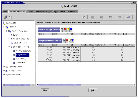
FIGURE 3-3 Numeric Voltage Sensors and Voltage Threshold Sensors Tables (Sun Fire V250 Shown)

Numeric Sensors
TABLE 3-14 shows the properties for numeric sensors.
TABLE 3-14 Numeric Sensor Table Properties
|
Property
|
Comments
|
|
Name
|
Unique name
|
|
Location
|
Path to the device location
|
|
Description
|
Informal component description
|
|
Operational Status
|
Current component status
|
|
Additional Info
|
Supporting information for Operational Status
|
|
Current Reading
|
Current sensor reading
|
|
Units
|
Reading units
|
|
Lower Non Critical Threshold
|
Lower first warning threshold
|
|
Upper Non Critical Threshold
|
Upper first warning threshold
|
|
Lower Critical Threshold
|
Lower second warning threshold
|
|
Upper Critical Threshold
|
Upper second warning threshold
|
|
Lower Fatal Threshold
|
Lower final warning threshold
|
|
Upper Fatal Threshold
|
Upper final warning threshold
|
Non-Numeric Sensors
TABLE 3-15 shows the properties for non-numeric sensors.
TABLE 3-15 Non-Numeric Sensor Table Properties
|
Property
|
Comments
|
|
Name
|
Unique name
|
|
Location
|
Path to the device location
|
|
Description
|
Informal component description
|
|
Operational Status
|
Current component status
|
|
Additional Info
|
Supporting information for Operational Status
|
|
Current Reading
|
Current sensor reading
|
|
Normal Values
|
A list of values considered normal for this sensor
|


