| C H A P T E R 7 |
|
Sun MTP Tables |
The Sun MTP tables, also called the system tables, define programs, transactions, files, groups, remote systems, and other resources needed to run applications. The Table Manager tool is used to work with tables.
All system tables except the VCT are a subset of the tables required by CICS. Only those fields necessary to the operation of Sun MTP are maintained.
This chapter contains the following topics:
|
3. Type either transaction on a blank transaction screen:
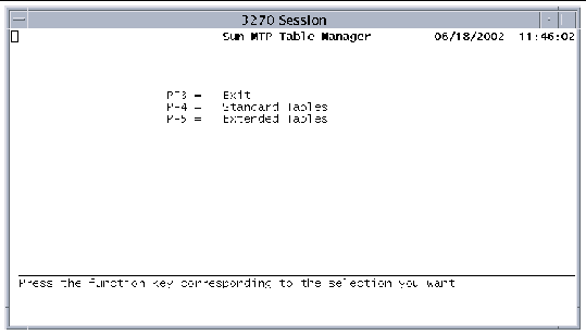
FIGURE 7-1 shows the Table Manager menu.
 [ D ]
[ D ]
The Table Manager main menu lists two submenus, Standard Tables and Extended Tables. To display the next menu level, press the appropriate function key.
The Table Manager has three types of screens:
The PF keys described in the following table operate in the same way for all tables.
The Sun MTP software is shipped with a set of pre-defined tables. Tables that contain unikix group entries are installed in the $UNIKIX/lib/unikix.tbl directory, and tables that contain rdo group entries are installed in the $UNIKIX/lib/rdo.tbl directory. User-defined tables are written to $KIXSYS or to directories specified in the Group Control Table (GCT).
When a region starts for the first time, the tables in the $UNIKIX/lib/unikix.tbl directory are copied to $KIXSYS/unikix.dir and the tables in the $UNIKIX/lib/rdo.tbl directory are copied to $KIXSYS/rdo.dir.
|
Note - If $KIXSYS/unikix.dir or $KIXSYS/rdo.dir is removed, the tables from $UNIKIX/lib/unikix.tbl and $UNIKIX/lib/rdo.tbl are copied to $KIXSYS/unikix.dir and $KIXSYS/rdo.dir at the next startup. |
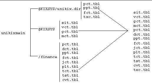
Every time a region starts, the entries in the pre-defined tables, the tables in $KIXSYS, and the tables located in the directories specified in the GCT are merged. When you open a table you see the combined entries. The tables are opened in the following order:
1. All tables in $KIXSYS, including the SIT, VCT, GCT, and MCT.
2. The internal tables in $KIXSYS/unikix.dir.
3. Tables in other directories in the order in which the directories appear in the GCT. Typically, if table entries are duplicated among groups, the first entry found is the active one. If you are using alternate resource definition, duplicate entries are handled differently. Refer to the Sun Mainframe Transaction Processing Software Configuration Guide for information about alternate resource definition.
FIGURE 7-2 shows the table merging process when alternate resource definition is not enabled. In this figure, the /finance directory is defined as a group in the region's GCT.
 [ D ]
[ D ]
See Grouping Table Entries for information about grouping tables for an application.
A proprietary format is used for the system tables, which have .tbl extensions. Tables in this format can be viewed only in Table Manager. The software enables you to export and import table data, which can facilitate editing large numbers of entries. When Sun MTP exports data from a table, it creates the file name $KIXSYS/tablename.lst; for example, $KIXSYS/sit.lst. The .lst files are in ASCII file format, so that you can read and modify them with any text editor. When a table contains more than one entry, each entry is displayed on a separate line.
|
Note - Contact your authorized service provider if you need information about any of the table file formats. |
Neither the import nor the export function issues a prompt or warning before executing. When you import a .lst file, the Table Manager overwrites the existing table (.tbl file) in memory if there are no errors. As long as you do not save the table to the disk, the existing table on the disk remains unaltered; you can redisplay it by exiting and reopening the Table Manager. When you export a table, if a .lst file exists on the disk, it is overwritten. FIGURE 7-3 shows how the import and export functions work.
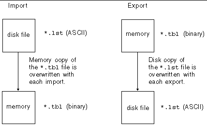
When table data is imported, it is validated as if you had typed it manually. If there are any errors, the table is not imported and an error screen listing each entry containing an invalid field is displayed.
See Chapter 2 for information about the kiximptbl and kixexptbl utilities, which import and export region tables.
Because you can use a region for many applications, it is sometimes difficult to identify the table entries that belong to a particular application. One way to address this situation is to create a separate region for each application. Another way is to use the GCT to create groups. A group is a logical way of organizing resources.
In the GCT, you create a group name and specify a directory in the file system where the group's resource definitions will be stored. Most tables have a Group field, where you can specify the name of the group to which the resource belongs. Single-entry tables, such as the System Initialization Table (SIT), do not have a Group field. See Group Control Table (GCT).
Once you establish groups, you can assign the application's resources (programs, mapsets, and so on) to a specific group. The tables where these resources are defined are saved to the group directory. For example, you create the finance group in the GCT and specify the /users/finance/sys directory. You then define your application's resources and assign files, programs, transactions, and terminals to the finance group. The group directory will contain fct.tbl, ppt.tbl, pct.tbl, and tct.tbl files.
If you do not assign your application resources to a group, the tables that contain the resource definitions are stored in the $KIXSYS directory.
kixupdateGCT is a command-line utility that inserts, modifies, and deletes GCT entries. See kixupdateGCT - Update GCT.
Four tables provide search capability: the File Control Table (FCT), Program Control Table (PCT), Processing Program Table (PPT), and Sign-On Table (SNT). On the main screen for each of these tables, the PF10 key displays a Lookup screen, where you specify the search criteria. Each Lookup screen contains three fields: a primary key, a secondary key, and an exact match option. The primary search key for all tables is the Group name field. The secondary keys are as follows:
The exact match option indicates whether to perform an exact match search or a partial, inexact match search. The table shows sample valid search criteria for the PPT.
After you specify the search criteria and press Enter, a binary search is performed on the table. If you specify an inexact match, the binary search finds the first entry in the table that meets the criteria. If the table search does not find a match, the following message is displayed:
Use the kixcnvtbl80 utility to convert tables created with Release 4.0, 4.1, 5.0, 5.1, 6.0, and 7.x to the format used by the current release. This utility converts all tables in the specified directory. You must convert all tables in order to use them, including tables that reside in directories defined in the GCT. If you specify a directory that contains the GCT, kixcnvtbl80 converts all the tables in the directories defined in the GCT.
kixcnvtbl80 - Convert Tables explains how to use the utility. Also, refer to the Sun Mainframe Transaction Processing Software Administrator's Guide for instructions for modifying the conversion table file to support languages other than U.S. English.
The Standard Tables menu lists the following options. To display or modify a table, press the corresponding function key.
|
 Press PF4 on the Table Manager main menu.
The System Initialization Table (SIT) contains data that a region uses for system initialization. Display the SIT by pressing PF1 on the Standard Tables menu.
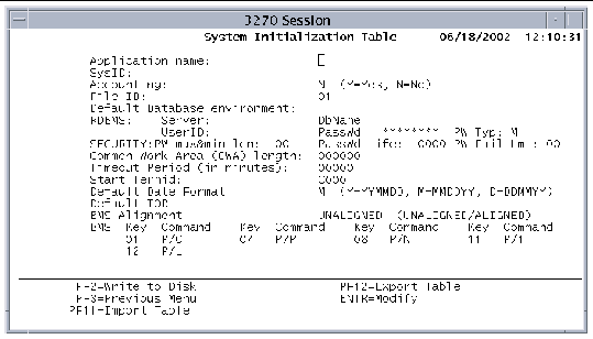
The SIT contains the following fields:
|
Identifies the application name, up to eight characters. This is the value returned with the APPLID option of the ASSIGN command, and the APPLID or JOBNAME options on the INQUIRE SYSTEM command. This is also the name used by the Administration Tool to display the region that is being monitored. This field is required for transaction routing. Refer to the Sun Mainframe Transaction Processing Software Administrator's Guide for more information. |
|
|
Specifies a system identifier. Optional four-character field; the value that is returned with the SYSID option of the ASSIGN command. |
|
|
Indicates if global accounting is enabled. Required field. The default is N. N: No accounting records are produced regardless of any other settings. Y: Accounting is enabled, and specifications based on the user ID and transaction ID take effect. You must also specify the next field, File ID. See also Monitoring Control Table (MCT). |
|
|
Identifies the journal file; two-digit numeric value. If File ID is not specified in the JCT, the journal file name is created by concatenating JRNL with File ID--creating, for example, a journal file named JRNL05. |
|
|
Environment variable specifying the directory that contains the VSAM Catalog (CATALOG.idx and CATALOG.dta files). Refer to the Sun Mainframe Transaction Processing Software Administrator's Guide for more information. |
|
|
These four fields are returned in the RDBMS user exit program. The user exit programs can be called during initialization to connect to the related database. Server: Identifies the server for connection to RDBMS user exit programs. DbName: Relational database name for connection to the RDBMS user exit programs. UserID: Relational database user name for connection to the RDBMS user exit programs. PassWd: Relational database password for connection to the RDBMS user exit programs. |
|
|
Specifies the type of password that will be valid when the current password is changed using the EXEC CICS CHANGE PASSWORD command or the CESN and CSSN transactions. Type one of these values: N: New password must be numeric (0-9) A: New password must be alphabetic (A-Z, a-z) M: New password can be any combination of numbers, letters, or other characters. The default. |
|
|
Specifies the maximum and minimum password length. The format of this two-digit field is MN where M is a single-digit value for the maximum password length from 1-8 characters and N is a single-digit numeric value for the minimum password length from 1-8 characters. If set to zero, no password length checking is done. A password of any length in the range of 1-8 is accepted when a password is changed using either the EXEC CICS CHANGE PASSWORD command or the CESN and CSSN transactions. |
|
|
Specifies the number of days a newly changed password is valid. This four-digit field applies to all user IDs in a region. Valid entries are in the range 0000-9999. If set to zero, no checking for password expiration is done. |
|
|
Two-digit field that specifies the number of consecutive password failures that can occur before the system automatically suspends the user's password. Valid entries are in the range 00-99. If set to zero, no password failure count checking is done. This is the default. Failure counts on a per user basis are maintained only in shared memory and are not retained when a region is restarted. As soon as a user accesses a valid password, the password failure count is reset to zero for that user ID. |
|
|
Amount of storage area to allocate for the CWA during system initialization; a decimal integer from 0 through 32,767. |
|
|
Timeout period for inactive terminals. The region automatically logs off any terminals that are inactive for this period (in 2-minute intervals), regardless of how they are connected. The default is 0, which does not disconnect inactive terminals. |
|
|
Starting terminal identifier for the region.The format is a single character plus three digits; for example, C000. The region uses this identifier to distinguish a terminal from the mainframe terminal identifier. The terminal identifier is assigned to a given user session at the time that a user starts a client. The actual terminal identifier is assigned based on the order in which the client was connected. |
|
|
Format of the date returned by the FORMATTIME command for the options DATE and DATEFORM. Y: Year/month/day format: YYMMDD or YYYYMMDD |
|
|
Terminal-owning region (TOR) for the local system. This field applies to the "terminal not found" user exit. Refer to the Sun Mainframe Transaction Processing Software Administrator's Guide for more information. |
|
|
Alignment of maps, either halfword-aligned or unaligned. Halfword alignment pertains to a method used on older IBM mainframes to speed up the accessing of BMS maps. The length fields in the BMS maps were padded with a filler character, where necessary, to ensure that they ended at halfword boundaries. When you set this field, all maps that this region uses must be assembled with the same option. When you export the SIT, this field is exported as U for unaligned or A for aligned. UNALIGNED
ALIGNED
|
|
|
Define up to eight keys to control the CSPG transaction used for BMS paging. Each key corresponds to a BMS page command. To invoke a BMS command, press a defined key while executing a CSPG transaction. |
The supported BMS paging commands are listed in the following table.
TABLE 7-4 shows the default values for the SIT.
A region can temporarily save data in the form of queues, called destinations. The Destination Control Table (DCT) contains a list of destination names or queues that can be processed by transient data commands, as well as characteristics associated with these queues.
There are three types of entries in the DCT:
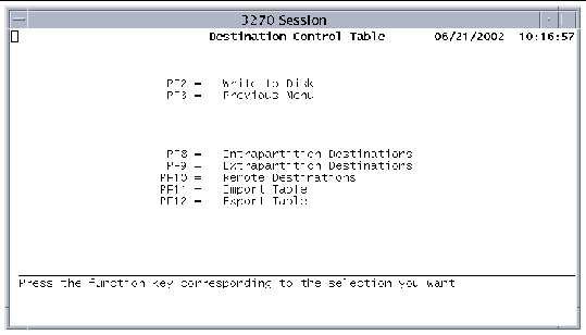
To display the DCT menu shown in FIGURE 7-5, press PF4 on the Standard Tables menu.
 [ D ]
[ D ]
Press the appropriate function key to access the table type you want to modify.
FIGURE 7-6 shows the Intrapartition Destinations screen, which displays those entries in the DCT that are intrapartition destinations. Press PF8 on the DCT menu to display this screen.
All intrapartition transient data (TD) destinations are held as queues in the same dataset, and thus in the same region. Data is written to the queue by a user task. Other tasks running in the region can subsequently access the data. All access is sequential and is governed by read and write pointers. After a record has been read, it cannot subsequently be read by another task. An intrapartition destination requires a resource definition containing information that locates the queue in the intrapartition data set. Applications that might use intrapartition queues include message switching, data collection, and queuing of orders.
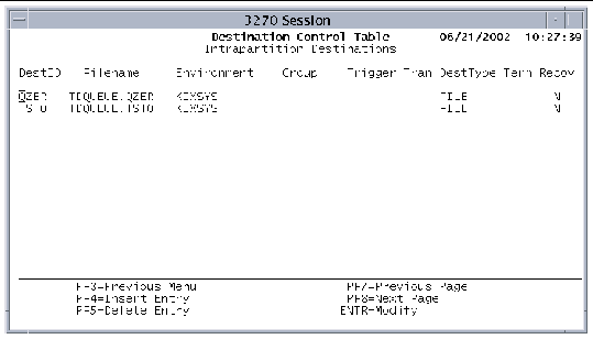
For each intrapartition destination, the following information is maintained:
|
Identifies the file to write data to or read data from. Required. |
|
|
Environment variable containing the name of the directory in which Filename resides. |
|
|
Identifies the group specified in the Group Name field of the GCT. If a group name is specified in the GCT, this field contains that value. See Group Control Table (GCT). When you press the PF2 key on the DCT screen, this entry is written to dct.tbl in the directory specified in the GCT Directory field, if the read-only indicator (R/O field) is set to No for this group. If this field is blank, the entry is read or written to the dct.tbl file in the $KIXSYS directory. |
|
|
Number of records in the dataset required to automatically trigger the execution of a transaction to process the records; a decimal number from 0 to 99999. |
|
|
Transaction initiated when the trigger level is reached. This four-character field (uppercase and lowercase characters allowed) must match a Trans ID entry in the PCT. See Program Control Table (PCT). |
|
|
Destination; either TERMINAL or FILE. During system initialization, any entry with a DestType of FILE is assigned to a KSDS VSAM file, which contains the data read or written. The file is variable-length; the maximum record length that can be written to the file is 32,763 bytes. |
|
|
Terminal identifier defined in the TCT. When a transaction is triggered, it runs against this terminal ID. This field is valid only if the DestType is TERMINAL. |
|
|
Specifies whether or not the transient data queue is recoverable. If Y, the queue is recoverable. Recovery of intrapartition queues takes place during standard KSDS recovery. |
1. Press PF4 on the Intrapartition Destinations screen to display the Insert screen.
2. After you finish making your entries, press Enter.
3. Save the table to the disk.
Press PF9 on the DCT screen to display the Extrapartition Destinations screen. Each extrapartition destination requires a resource definition that links it to a sequential file outside the region. Extrapartition destinations are used for data that is either coming from a source outside the region or being directed from a source within the region to a destination outside the region. Extrapartition data written by the region is usually intended for subsequent input to external batch programs. Data that might be written to extrapartition destinations include logging records, statistics, and transaction error messages.
During system initialization, all entries defined as extrapartition destinations are assigned to a sequential file that contains the data written. The file is opened with the record format and length specified in the entry.
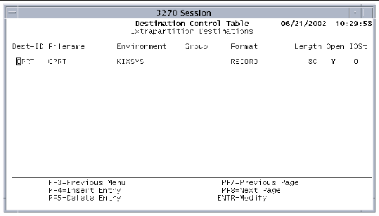
For each extrapartition destination, the following information is maintained:
|
Identifies the file to write data to or read data from. Not valid for JOB or PRINT formats. |
|
|
Environment variable containing the directory for Filename. Not valid for JOB or PRINT formats. |
|
|
If a group name is specified in Group Name field of the GCT, this field contains that value. See Group Control Table (GCT). When you press the PF2 key on the DCT screen, this entry is written to dct.tbl in the directory specified in the GCT Directory field, if the read-only indicator (R/O field) is set to No for this group. If the group field is blank, the entry is read or written to the dct.tbl file in the $KIXSYS directory. |
|
|
Record format of the file: JOB, LINE, PRINT, RECORD, or RECORDV. The format field determines the type of data that can be written to the queue. RECORD format supports fixed-length records of character or binary data. No control information is contained in files that have the RECORD format. RECORDV format also supports fixed-length records of character or binary data; however, the size of each record is given in a full word binary field prior to each record. If you define the format as JOB, no entries are required in the Filename and Environment fields. LINE, PRINT, and JOB are all line sequential files. This limits these files to character data. The PRINT and JOB formats are also associated with the kixprint and kixjob shell scripts, which are automatically called on a syncpoint. The files are deleted and reinitialized after printing or transfer to the job queue. For more information about the kixjob and kixprint shell scripts, see Chapter 2. |
|
|
Record length, or in the case of variable-length records, the maximum record length; from 0 to 9,999. |
|
1. Press PF4 on the Extrapartition Destinations screen to display the Insert screen.
2. After you finish adding entries, press Enter.
3. Save the table to the disk.
Press PF10 on the DCT screen to display the Remote Destinations screen. Remote destinations are those that are owned by a Sun MTP region on another system.
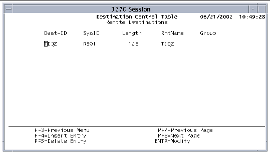
For each remote destination, the following information is maintained:
|
Four-character field that specifies a system identifier that is also an entry in the Terminal Control Table--System Entries table. If there is an entry in this field, the destination is considered remote. See Terminal Control Table-System Entries. You can access the remote destination only if the remote system is operating. |
|
|
Record length, or in the case of variable-length records, the maximum record length; from 0 to 32,767. |
|
|
Identifies the name by which the destination is known on the remote system, up to four characters. This field is used if the local and remote names are different. By default, the local and remote names are the same. Sun MTP substitutes the remote name before sending the request to the remote system. |
|
|
If a group name is specified in the Group Name field of the GCT, this field contains that value. See Group Control Table (GCT). When you press the PF2 key on the DCT screen, this entry is written to dct.tbl in the directory specified in the GCT Directory field, if the read-only indicator (R/O field) is set to No for this group. If the group field is blank, the entry is read or written to the dct.tbl file in the $KIXSYS directory. |
1. Press PF4 on the Remote Destinations screen to display the Insert screen.
2. After you finish adding entries, press Enter.
3. Save the table to the disk.
The File control Table (FCT) contains information about an application's VSAM files. Associated with each file is a set of characteristics that the region uses to validate and execute commands issued by application programs. For each entry in the FCT, there must be a corresponding entry in the VSAM catalog. Refer to the Sun Mainframe Transaction Processing Software Administrator's Guide for information about the VSAM catalog.
The FCT has two information screens. The first, shown in FIGURE 7-9, contains general information. The second shows information about remote files. To display the general information screen, press PF5 on the Standard Tables menu.
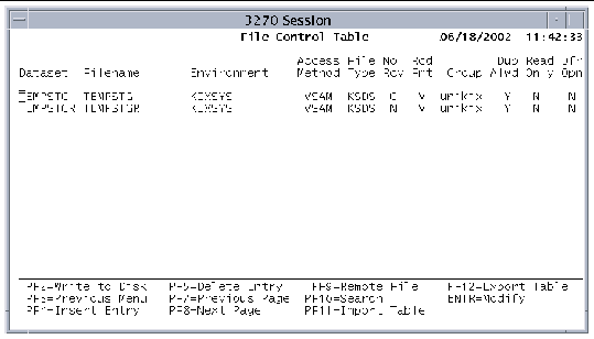
The FCT general information screen contains the following fields:
|
Dataset name by which a program references the file. You can associate more than one logical dataset with a single physical VSAM file (file name qualified by its environment). These dataset names are called aliases. |
|
|
Physical file name associated with the dataset or alternate index. You can associate a single file name, qualified by its environment, with up to eight logical dataset names. Key-sequenced datasets (KSDS):
Entry-sequenced datasets (ESDS) and relative-record datasets (RRDS):
Alternate index files:
The Filename entry must match an entry in the VSAM catalog. If you associate more than one dataset to the same file name, the corresponding attributes in all remaining fields, except Read Only or Dfr Opn, must be identical. If you change a field in an entry for a file that has aliases, the change will be propagated to all the entries. |
|
|
Environment variable pointing to the directory for the file name. |
|
|
VSAM (Virtual Storage Access Method). No other access methods are currently supported. |
|
|
File organization of the VSAM file. |
|
|
Indicates whether recovery is active for a specific file. This field overrides the recovery option set in the VCT if recovery is enabled. If recovery is not enabled in the VCT, this field is ignored. See VSAM Configuration Table (VCT). C: Disable recovery and enable use of system cache for the VSAM file. This option is the default for the nonrecoverable temporary storage file. Refer to the Sun Mainframe Transaction Processing Software Administrator's Guide for additional information. When multiple dataset entries use the same physical file, Table Manager verifies that all datasets for that file have the same option specified in the No Rcv field, and reports an error if they are not consistent. |
|
|
Record format. This value is used in the validation of some CICS commands. |
|
|
If a group name is specified in the Group Name field of the GCT, this field contains that value. See Group Control Table (GCT). When you press the PF2 key on the FCT screen, this entry is written to fct.tbl in the directory specified in the GCT Directory field, if the read-only indicator (R/O field) is set to No for this group. If the group field is blank, the entry is read or written to the fct.tbl file in the $KIXSYS directory. |
|
|
Indicates whether duplicate keys are allowed for alternate indexes. |
|
|
Indicates whether the dataset is opened during startup. Y: Dataset is left closed during startup. You can open and close datasets and change the status of datasets while the region is running by using the kixfile utility. Refer to the Sun Mainframe Transaction Processing Software Administrator's Guide and kixfile - Change Dataset Status for more information. |
Display the Remote File Characteristics screen shown in FIGURE 7-10 by pressing PF9 on the FCT screen. Use the Remote File Characteristics screen to specify attributes for files that are used by intersystem communication (ISC) function shipping. Refer to the Sun Mainframe Transaction Processing Software Administrator's Guide for more information.
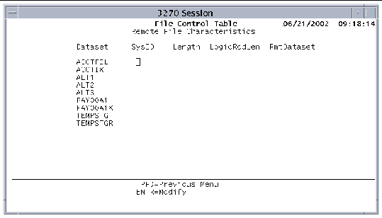
For each remote file, the FCT maintains the following information:
1. Press PF4 on the FCT screen to display the Insert screen.
If you define a dataset with a file name already associated with other datasets, the corresponding attributes in all remaining fields, except Read Only or Dfr Opn, must match the existing dataset definitions, or the field is flagged as an error. If the file name already has the maximum of eight associated datasets, the field is flagged as an error.
3. After you are finished, press Enter.
4. If the dataset is remote, select it on the FCT screen and press PF9.
5. On the Remote File Characteristics screen, type information in the required fields, and press Enter.
6. Repeat steps 4 and 5 for each remote dataset.
7. Save the table to the disk.
Display the FCT-Lookup screen by pressing PF10 on the FCT main screen. The Lookup screen enables you to search for a dataset.
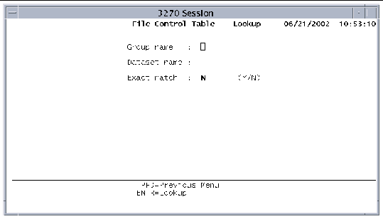
To search for a dataset in the FCT, enter values in the following fields:
Press Enter to start the search. If a match is found, the FCT main screen is displayed. The cursor is positioned on the first match. See also Searching Tables.
Press PF3 to cancel the search and return to the FCT main screen.
The Program Control Table (PCT) contains information that is used to identify and initialize a transaction, and it is one of the four tables required to run an application. Press PF6 on the Standard Tables menu to display the PCT.
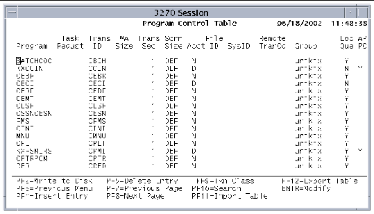
The PCT contains the following information:
|
Program name. Do not include extensions. Program names must be uppercase because they are used in CICS commands. For COBOL programs, these are programs with a .gnt or .int extension. If both a .gnt and .int exist, the .gnt takes precedence. For PL/I and C programs, these are programs with a .so extension. For Java programs, these are programs with a .class extension. |
|
|
Key that initiates this program as a transaction. If this field is blank, no key initiates this program as a transaction. Valid values are: |
|
|
Identifier, one to four characters, that initiates the program as a transaction. This field can contain both uppercase and lowercase characters; lowercase letters are translated to uppercase. |
|
|
Transaction work area (TWA) size in bytes; from 0 to 32,767. |
|
|
A number from 1 to 64 specifying a transaction security level. This value corresponds to a bit value set in the Security Key area of the SNT associated with the user at the terminal that entered the transaction. If external security management is enabled (KIXSEC=YES), the value in Trans Sec is ignored. Refer to the Security chapter in the Sun Mainframe Transaction Processing Software Administrator's Guide. The Security Key is set for a user by the SNT when the user signs on explicitly with CSSN (CESN), or implicitly when a region starts and a match is found between the user ID and a user ID in the SNT. By default, each user is allowed to enter transactions only with a security level of 1. All system transactions are set initially to a transaction security level of 1, which allows all users to access them. Raise the security level for critical transactions, such as CSMT, CEMT and other transactions that are used to configure the region's environment. Refer to the Sun Mainframe Transaction Processing Software Administrator's Guide for information about the system transactions and security. |
|
|
Default screen size or the alternate screen size. DEF: Default screen size of 24 lines and 80 columns for Model 2 3270 terminal types ALT: Alternate screen sizes of 27 lines and 132 columns for Model 5 3270 terminal types, or 43 lines and 80 columns for Model 4 3270 terminal types |
|
|
Indicates whether accounting is on or off for this transaction. Y: Accounting is on for this transaction, if the Accounting field in the SIT is set to Y. N: Accounting is off for this transaction. D: (Default) Accounting is controlled by the SIT Accounting field and the MCT. |
|
|
Journal file identifier for this transaction; a number from 1 to 99. If accounting is set to N, this field is ignored. If File ID is not specified in the JCT, the journal file name is created by concatenating JRNL with File ID, creating, for example, a journal file named JRNL05. |
|
|
Four-character system identifier that is also an entry in the TCT - System Entries table. If this field contains a value, the region routes or ships transactions to the remote system for processing. Refer to the Sun Mainframe Transaction Processing Software Administrator's Guide for more information about routing and shipping transactions. |
|
|
Transaction code used on a remote system when routing this transaction or when using asynchronous processing of transactions on a remote system. |
|
|
If a group name is specified in the Group Name field of the GCT, this field contains that value. See Group Control Table (GCT). When you press the PF2 key on the PCT screen, this entry is written to pct.tbl in the directory specified in the GCT Directory field, if the read-only indicator (R/O field) is set to No for this group. If the group field is blank, the entry is read or written to the pct.tbl file in the $KIXSYS directory. |
|
|
Type Y or N to specify whether transactions shipped to a remote system are locally queued if the remote system is unavailable. Refer to the Sun Mainframe Transaction Processing Software Administrator's Guide for information about ISC. |
|
|
Y: Transaction is a back-end DTP program and performs ISC functions. N: Transaction is not a back-end DTP program. It can still perform outbound ISC functions, but does not run as expected if started by a remote Sun MTP or CICS region. |
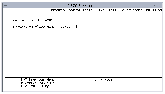
Display the Transaction Classes screen by pressing PF9 on the PCT screen. Assign transactions to transaction classes on this screen.
1. Press PF4 on the PCT screen to display the Insert screen.
3. After you are finished, press Enter.
4. If you want to assign the transaction to a transaction class, select the transaction and press PF9.
5. On the PCT Transaction Classes screen, specify the transaction class for this transaction, and press Enter.
6. Repeat steps 4 and 5 for each transaction you want to assign to a class.
7. Save the table to the disk.
Display the PCT-Lookup screen by pressing PF10 on the PCT main screen. The Lookup screen enables you to search for a transaction ID.
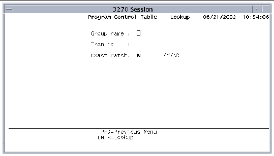
To search for a program in the PCT, type values in the following fields:
Press Enter to start the search. If a match is found, the PCT main screen is displayed. The cursor is positioned on the first match. See also Searching Tables.
Press PF3 to cancel the search and return to the PCT main screen.
The Processing Program Table (PPT) lists the online programs that Sun MTP can execute, the tables that can be loaded, and the mapsets that can be referenced. It is one of the four tables required to run an application. Display the PPT by pressing PF7 on the Standard Tables menu.
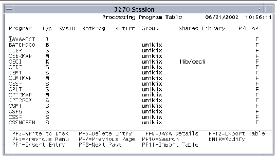
The PPT contains the following information:
|
Identifies the name of a program, table, or mapset. Mapset names must be unique and can contain no more than seven characters. |
|
|
A: Table referenced by the CICS LOAD and RELEASE commands |
|
|
Four-character field that specifies an entry in the TCT--System Entries table. If there is a value in this field, the program is considered a remote program. You can access the remote program only if the remote system is operating. |
|
|
Program name on the remote system. Use this field if the local and remote names are different. By default, the local and remote names are the same. Refer to the Sun Mainframe Transaction Processing Software Administrator's Guide for additional information. |
|
|
Transaction code to use on a remote system to perform the Distributed Program Link (DPL) function when this program is remote. The name can be changed for security or accounting purposes. Refer to the Sun Mainframe Transaction Processing Software Administrator's Guide for more information. |
|
|
If a group name is specified in the Group Name field of the GCT, this field contains that value. See Group Control Table (GCT). When you press PF2 on the PPT screen, this entry is written to ppt.tbl in the directory specified in the GCT Directory field, if the read-only indicator (R/O field) is set to No for this group. If the group field is blank, the entry is read or written to the ppt.tbl file in the $KIXSYS directory. |
|
|
Identifies the shared library or shared object, up to 16 characters, where the program is found. All entries are relative to $KIXSYS unless the KIXLIB environment variable is set. |
|
|
Set this field to Y if you want the transaction server to open the shared object when it starts up. Otherwise, set this field to N or leave it blank. Refer to the Sun Mainframe Transaction Processing Software Developer's Guide for more information about how shared objects are loaded. |
|
|
Defines local testing of the DPL functionality: F: Any CICS command is available to the server program (default). D: The server program is not allowed to execute any of the DPL-restricted API. Refer to the Sun Mainframe Transaction Processing Software Administrator's Guide for more information about DPL. |
The Java Class Details screen is used to specify the fully qualified class name of the selected Java program. Select a Java program and press PF9 on the PPT main screen to display the Java Class Details screen.
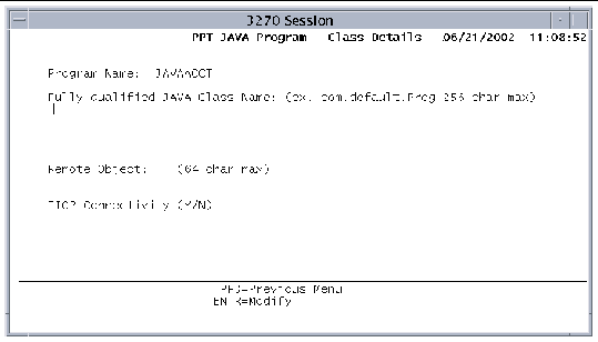
The fields on the Java Class Details screen are:
When you have Java programs defined in the PPT and save the PPT to the disk, a jva.tbl file is created. If no Java programs are defined, the jva.tbl file is not created. The jva.tbl is used at region startup to build a shared memory table that contains the Java class names for all the Java entries in the PPT. During runtime, this table maps Java programs to their corresponding classes.
Refer to the Sun Mainframe Transaction Processing Software Developer's Guide for information about using the Java CICS (JCICS) API.
1. Press PF4 on the PPT screen to display the Insert screen.
3. After you are finished, press Enter.
4. If you added a Java program, select it on the PPT main screen, and press PF9.
5. On the Java Class Details screen, specify the Java class name and press Enter.
6. Repeat steps 4 and 5 for each Java program you added.
7. Save the table to the disk.
Display the PPT-Lookup screen by pressing PF10 on the PPT main screen. The Lookup screen allows you to search for a program.
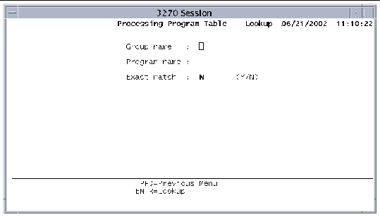
To search for a program in the PPT, type values in the following fields:
Press Enter to start the search. If a match is found, the PPT main screen is displayed. The cursor is positioned on the first match. See also Searching Tables.
Press PF3 to cancel the search and return to the PPT main screen.
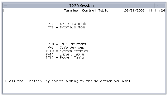
The Terminal Control Table (TCT) contains information about printers, 3270 devices, and remote systems. To display the TCT menu, press PF8 on the Standard Tables menu.
 [ D ]
[ D ]
There are three types of entries in the TCT:
The Terminal Control Table-Printers screen defines terminal identifiers that can be used in CICS commands. You can then associate these terminal identifiers with physical or logical printers. Refer to the Sun Mainframe Transaction Processing Software Configuration Guide for procedures to configure printers.
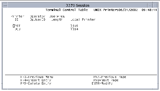
The TCT-Printers Screen contains the following information:
|
Display-only field containing the identifier associated with your printer. Printer identifiers can be referenced by Intrapartition Destinations entries whose destination type is TERMINAL or PRINTER. They can also be referenced by the TERMID option of the EXEC CICS START command. See Destination Control Table (DCT) for more information about Intrapartition Destinations. |
|
|
An eight-character field that must match the User ID field in an SNT entry so that printer security is copied to the TCT. |
|
|
The number of bytes of terminal-associated storage that is accessible to an application at execution time. It is assigned to the terminal during system initialization and remains while the region is executing. It is a value from 0 to 255 and is equivalent to TCTUAL in CICS. |
|
|
Designates the physical printer and can contain any 14 characters. If present, it is passed to the kixprint shell script as a -p parameter. See the Sun Mainframe Transaction Processing Software Configuration Guide for information about modifying kixprint. |
1. Press PF4 on the Printers screen to display the Insert screen.
3. After you are finished, press Enter.
4. Save the table to the disk.
Press PF9 on the TCT menu screen to display the 3270 Devices main screen. It contains information about 3270 devices, such as printers, that cannot log themselves in to the region.
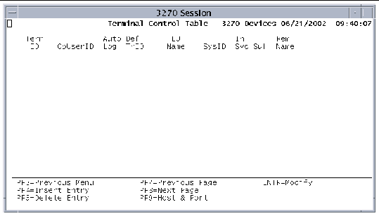
The following information is displayed on the main 3270 Devices screen:
|
Terminal identifier as known to the application. This four-character field is required and cannot be the same as any other TCT Term ID. |
|
|
An eight-character field that matches the User ID field in an SNT entry. |
|
|
Optional field that indicates whether the region should try to connect to this terminal when the 3270 client initiator is enabled. Valid one-character entries are: y, Y, n, N. The default is Y. If set to N or n, the terminal can be activated or logged into the region with the CEMT transaction. Refer to the Sun Mainframe Transaction Processing Software Administrator's Guide for more information about CEMT. |
|
|
Transaction identifier that overrides any transaction identifier entered on the terminal. |
|
|
For SNA: Identifies the terminal as known to the SNA network. This eight-character field is required. LU names are configured when the SNA server is installed with the PU5 package. Refer to the PU5 documentation for more information about assigning LU names. For TN3270E: Identifies the terminal as known to the TN3270E emulator. This optional field enables you to predefine a TN3270E terminal. You must define the LU name in the TN3270E startup procedure in the emulator. |
|
|
System identifier. If this four-character field is blank or matches the SysID configured in the SIT, the local system is used. If a different value is specified, it defines the terminal as remote. The remote system must also be defined as a system entry in the TCT. See Terminal Control Table-System Entries. |
|
|
(In Service) Initial state of the terminal. Remote connections ignore this field. |
|
|
Suffix added to all seven-character mapsets used for BMS mapping requests. You can use this optional field for alternate screen sizes or national language support in applications. |
|
|
Terminal identifier as it is known on the remote system. This field is used if two terminals with the same terminal ID on different remote systems will both be routing transactions to Sun MTP. Define one of the terminals as having a remote name as defined on the remote system and a unique Term ID. |
To display the TCT-3270 Devices, Host & Port screen, press PF9 on the TCT-3270 Devices main screen. The screen shows the host and port where the device is connected.
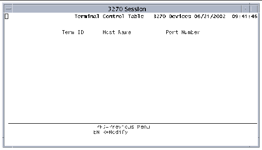
The following information is maintained on the Host & Port screen:
|
Terminal identifier. This field is the same as the Term ID field on the main screen. |
|
|
Identifies the host to which the 3270 devices are connected. If this 16-character field is blank, Sun MTP substitutes the name of the host on which the region is executing. |
|
|
Four-digit port number or a port name, up to 16 characters, on which unikixi, the Client Initiator process, listens for SNA or Sun MTP auto-login requests. See unikixi - 3270 Client Initiator Process. |
1. Pressing PF4 on the TCT-3270 Devices screen to display the Insert screen.
3. After you are finished, press Enter.
4. On the TCT-3270 Devices screen, select a new entry and press PF9.
5. On the Host & Port screen, type the required information, and press Enter.
6. Repeat steps 4 and 5 for each new entry.
7. Save the table to the disk.
The Terminal Control Table-System Entries screen contains a list of remote system identifiers (SysID). Associated with each SysID is all information applicable to that remote system. When an application program specifies the SYSID option in a CICS command, the specified identifier is validated against the list of SysIDs in the table.
To modify this table, press PF10 on the TCT menu.
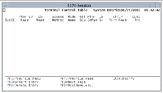
The TCT maintains the following information for each remote system.
After you create an entry for a system, you can display the Host Name screen by selecting the entry and pressing PF9 on the TCT-System Entries screen. The Host Name screen is where you enter the name of the host that corresponds to a SysID, and its network qualified partner name, if the host is accessed by means of an SNA connection.
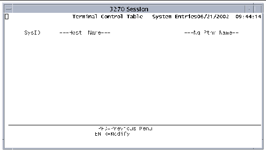
The Host Name screen contains the following fields:
1. Display the Insert screen by pressing PF4 on the TCT-System Entries screen.
2. Add new system identifiers.
3. Press Enter when you have finished.
4. On the TCT-System Entries screen, select an entry and press PF9.
5. On the Host Name screen, add host name information and press Enter.
6. Repeat steps 4 and 5 for each new system ID.
7. Save the table to the disk.
The VSAM Configuration Table (VCT) contains data that controls the operation of Sun MTP. Display the VCT by pressing PF10 on the Standard Tables menu. Type information directly on the VCT screen and press Enter when you have finished.
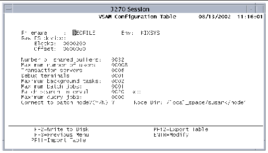
The VCT contains the following fields:
|
Identifies the recovery data file. If no recovery data file name is specified, standard recovery is not active. |
|
|
Environment variable that points to the directory where the recovery data file resides. |
|
|
Device name of the Native Recovery File System (NRFS). You must preconfigure NRFS. Refer to the Sun Mainframe Transaction Processing Software Configuration Guide for more information about configuring recovery. |
|
|
Number of blocks for the Sun MTP or NRFS recovery methods. The recovery file can be any size. The block size is set by unikixmain at startup.
4096 (4K) 524288
In either case, if this number is less than 100, recovery is not active. |
|
|
If you are using the recovery data file, this value must be 0. If you are using the Raw FS device, the offset value comes from the NRFS report. See kixnrfs - Configure NRFS. |
|
|
Number of 4KB buffers Sun MTP allocates at initialization for storing VSAM data in core. The minimum is 16; the default is 32. The maximum number of buffers is determined by the maximum shared memory segment size. Refer to the Sun Mainframe Transaction Processing Software Configuration Guide for more information. |
|
|
Number of users that can log in to the region at the same time. The default is 16 or the maximum number of users licensed for the system, whichever is number is lower. |
|
|
Cumulative number of transactions, debug sessions, or interactive query (IQ) jobs that can be active concurrently; up to 224. Refer to the Sun Mainframe Transaction Processing Software Configuration Guide for information about calculating the number of transaction servers. |
|
|
The maximum number of debug sessions that can be active, regardless of the number of transaction servers. This value cannot be greater than the value specified for transaction servers. |
|
|
Maximum number of transactions that can be started by CICS transient data triggers, and by START commands that do not specify the terminal ID. |
|
|
Maximum number of batch jobs that can execute concurrently. Refer to the Sun Mainframe Transaction Processing Software Developer's Guide for a description of batch processing. |
|
|
Interval, in seconds, between searches of the directory pointed to by $KIXBTCH. Setting this field to a low number can adversely affect online response time. Refer to the chapter on batch processing in the Sun Mainframe Transaction Processing Software Developer's Guide. |
|
|
Maximum number of interactive processes that can execute concurrently. |
|
|
Sun MBM installation path name, up to 189 characters. Required if you entered Y in the previous field. |
The Extended Tables menu lists the following options. To display or modify a table, press the corresponding function key.
|
 Press PF5 on the Table Manager main menu.
The Transaction Class Table (TXC) lists the transaction classes defined for the region. The two default classes are KIXADMIN and KIXDFLT. If you do not define any transaction classes, the region does not start the scheduler and run with transaction classes. Refer to the Sun Mainframe Transaction Processing Software Administrator's Guide for a description of transaction classes and instructions on how to use them. To display the TXC, press PF1 on the Extended Tables menu.
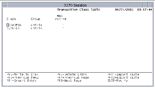
The following fields are displayed in the TXC:
1. Press PF4 on the TXC main screen to display the Insert screen.
2. Add new transaction classes.
3. After you are finished, press Enter.
4. Save the table to the disk.
The Program List Table (PLT) contains the names of programs executed during region initialization, startup for each user, or region termination. Associated with each program name is a value that indicates when to execute the program. Display the PLT by pressing PF4 on the Extended Tables menu.
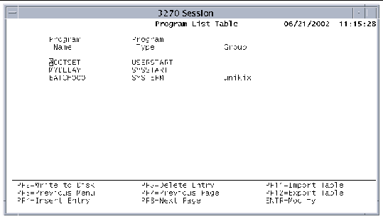
The PLT contains the following information:
|
Program to execute at the time specified by the Program Type field. These programs must exist in the PPT. |
|
|
Indicates when to execute the program. All programs of a specific type are executed in their order of appearance in this table. SYSSTART: Program executes when the system is initialized. |
|
|
If a group name is specified in the Group Name field of the GCT, this field contains that value. See Group Control Table (GCT). When you press PF2 on the PLT screen, this entry is written to plt.tbl in the directory specified in the GCT Directory field, if the read-only indicator (R/O field) is set to No for this group. If the group field is blank, the entry is read or written to the plt.tbl file in the $KIXSYS directory. |
1. Press PF4 on the PLT main screen to display the Insert screen.
3. After you are finished, press Enter.
4. Save the table to the disk.
The Sign-On Table (SNT) contains information used by the system sign-on transactions, CESN and CSSN, and the default sign-on process. The CESN transaction accepts a user ID and password, and the CSSN transaction accepts an operator name and password. The default sign-on process checks the user ID of the user accessing the region. In either case, if the user is found in the SNT, the security key, operator class, and operator identification for the user are merged with the information in the TCT that corresponds to the user's terminal.
Display the SNT by pressing PF5 on the Extended Tables menu.
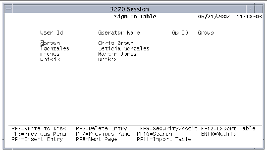
Information in the SNT is divided into identification information and security/accounting information. The first SNT screen displays identification information. You can display security and accounting information by selecting a user and pressing PF9.
The SNT identification information as follows:
|
Eight-character field that is used with the CESN transaction. This value is compared with the user ID. If a match is found, users are signed on to Sun MTP with their UNIX user ID. |
|
|
Alphanumeric name used to sign on to the region with the CSSN transaction; up to 20 characters. |
|
|
Operator identification. Three-character field that is copied to the TCT Operator OpUserID field when the user signs on. The data in this field is used by the ASSIGN command when requesting the OPID option. |
|
|
If a group name is specified in the Group Name field of the GCT, this field contains that value. See Group Control Table (GCT). When you press PF2 on the SNT screen, this entry is written to snt.tbl in the directory specified in the GCT Directory field, if the read-only indicator (R/O field) is set to No for this group. If the group field is blank, the entry is read or written to the snt.tbl file in the $KIXSYS directory. |
Display the SNT Security/Accounting screen (FIGURE 7-28) by selecting a user and pressing PF9 on the SNT main screen. The Security/Accounting screen enables you to enter additional information for the user. The first four fields identify the user. The remaining fields contain security and accounting information.
Security issue: When external security management is enabled (KIXSEC=YES), the values in the Password, Security Key, and Resource Key fields are ignored. The passwords in the SNT for the default user ID and for user IDs in predefined TCT entries are required and used, but only during startup. Refer to the Sun Mainframe Transaction Processing Software Administrator's Guide for more information about configuring usernames and passwords for Sun MTP Secure.
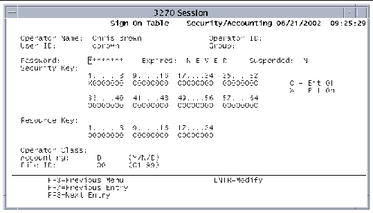
The SNT-Security/Accounting Information screen contains the following fields:
|
Eight-character password for the operator who is signing on. As you enter a password you can see what you are typing. This means that this field is unprotected. By default, this field accepts alphanumeric characters and will accept an all-numeric password. If you want to specify all numeric passwords or all-alphabetic passwords, you must set the password type field in the SIT before starting the region. See System Initialization Table (SIT). |
|
|
Date the password expires; display-only field. Updated only when a user changes the password with the CESN or CSSN transactions or if the password is changed with the EXEC CICS CHANGE PASSWORD command. |
|
|
Indicates whether the password has been suspended by the administrator. N: The password is not suspended (default). Y: The user ID/password is disabled. M: Forces the user to change the password the next time it is validated. If the administrator changes a password or the suspend status for a particular user ID in the SNT, the change becomes effective immediately. There is no need to restart the region. |
|
|
Sixty-four-byte field defining the security key used to compare with the transaction security level (Trans Sec field) set in the PCT. The data in this field is used by the ASSIGN command when requesting the OPSECURITY option. Entries are displayed in groups of eight. Users: Default is a security key with the first level on, giving users access to transactions that have their security keys set to 1. In FIGURE 7-28, this is indicated by the X in position 1. |
|
|
Twenty-four byte field that is merged with the TCT terminal entry when a user signs on. The data in this field is used by the ASSIGN command when requesting the OPERKEYS option. |
|
|
Three-character field that is copied to the TCT terminal entry when the operator signs on. The data in this field is used by the ASSIGN command when requesting the OPCLASS option. If you enter the value SYS, the user can perform the tasks specified in the System States table in the Sun Mainframe Transaction Processing Software Administrator's Guide. |
|
|
Y: Accounting is on for this user if the Accounting flag in the SIT is set to Y. N: Accounting is off for this user. D: (Default) Accounting is controlled by the SIT field and the MCT table. |
|
|
Journal file identifier for this user. If Accounting is set to N, this number is ignored. If File ID is not specified in the JCT, the journal file name is created by concatenating JRNL with File ID--creating, for example, JRNL05. |
1. Press PF4 on the SNT screen to display the Insert screen.
3. After you are finished, press Enter.
4. Select a user on the SNT screen and press PF9.
5. On the Security/Accounting screen, add any required information for the user and press Enter.
6. Repeat steps 4 and 5 for each new user.
7. When you are done, save the table to the disk.
Display the SNT-Lookup screen by pressing PF10 on the SNT main screen. The Lookup screen enables you to search for a user.
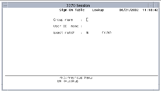
To search for a user in the SNT, type values in the following fields:
Press Enter to start the search. If a match is found, the SNT main screen is displayed. The cursor is positioned on the first match. See Searching Tables.
Press PF3 to cancel the search and return to the SNT main screen.
The Journal Control Table (JCT) is used to set up the journal files that will contain system and user accounting information. User journal files will hold messages written by the JOURNAL commands in your application programs.
Refer to the Sun Mainframe Transaction Processing Software Administrator's Guide for information about defining various types of accounting.
Display the JCT by pressing PF6 on the Extended Tables menu.
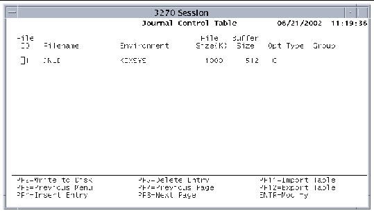
The JCT contains the following fields:
|
Journal file identifier used to determine the accounting file for a transaction or user; from 1 to 99. If you enable accounting in the SIT, this field must match the accounting File ID field in the SIT; it specifies the system journal. |
|
|
Environment variable containing the name of the directory where the journal file resides. |
|
|
Maximum journal buffer size in bytes; from 72 bytes to 32 KB. If a journal record is written that contains more characters than can fit in the buffer (after adding the system portion), the LENGERR exception condition is raised.
|
|
|
Indicates whether to cache journal files. Valid entries are: D: Do not use system cache. Retained for compatibility. (Default) C: Enable the use of system cache for the journal file. Refer to the Sun Mainframe Transaction Processing Software Administrator's Guide. |
|
|
If a group name is specified in the Group Name field of the GCT, this field contains that value. See Group Control Table (GCT). When you press the PF2 key on the JCT screen, this entry is written to jct.tbl in the directory specified in the GCT Directory field, if the read-only indicator (R/O field) is set to No for this group. If the group field is blank, the entry is read or written to the jct.tbl file in the $KIXSYS directory. |
1. Press PF4 on the JCT main screen to display the Insert screen.
3. Press Enter when you have finished.
4. Save the table to the disk.
Use the GCT to group all tables that belong to a specific application. When a region starts, all tables referenced by the group entries are opened. By adding and deleting groups, you can add or delete applications from a region.
Display the GCT screen by pressing PF7 on the Extended Tables menu.
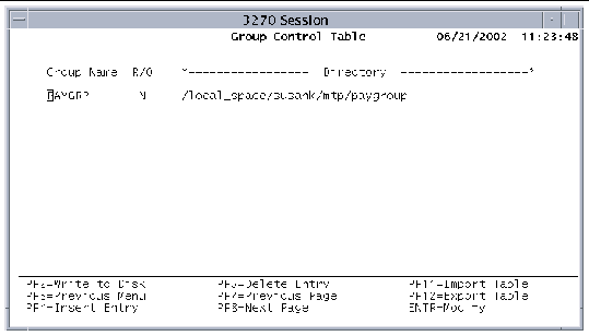
The GCT contains the following fields:
1. Press PF4 on the GCT screen to display the Insert screen.
3. After you are finished, press Enter.
4. Save the table to the disk.
The Monitoring Control Table (MCT) controls the default type of accounting that is active. This table contains a single entry with flags that control accounting. You can find additional controls in the SIT, PCT, and SNT. The SIT turns accounting on or off at a region-wide level. The PCT and SNT control accounting at the transaction and user levels, respectively. Display the MCT by pressing PF8 on the Extended Tables menu.
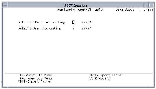
The MCT contains the following fields:
Use the Data Conversion Templates Table (CVT) to create templates for converting data from one code set to another, such as EBCDIC to ASCII. Data conversion is required when transmitting data between separate environments. Sun MTP converts data for both inbound and outbound requests, which means it is not necessary to code a DFHCNV macro, or similar macro, on the remote system.
The CVT can convert the following types of resources:
Defining the conversion to apply to a resource can require multiple entries in the CVT. Each entry describes a conversion template that can be applied to a resource. For a specific resource, you can define up to 256 separate templates.
Display the CVT by pressing PF9 on the Extended Tables menu.
To enter data into the CVT, fill in the summary screen, indicating which resource types and resources are to be converted. For each entry in the summary screen, you must specify conversion details. See Data Conversion Template Table-Detailed Information.
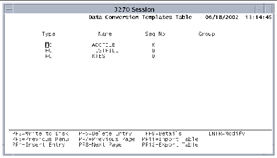
The fields on the CVT-Summary screen are as follows:
|
Identifies the name of resource to convert: |
|
|
If a group name is specified in the Group Name field of the GCT, this field contains that value. See Group Control Table (GCT). When you press the PF2 key on the CVT screen, this entry is written to cvt.tbl in the directory specified in the GCT Directory field, if the read-only indicator (R/O field) is set to No for this group. If the group field is blank, the entry is read or written to the cvt.tbl file in the $KIXSYS directory. |
Select a resource on the CVT-Summary screen and press PF9 to display the Detail Table, where you enter information for a specific conversion template. The first three fields identify the entry. The remaining fields are for data entry. FIGURE 7-34 shows the Detail Table for the Default definition.
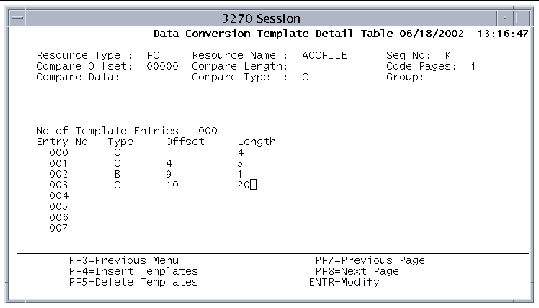
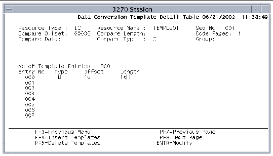
FIGURE 7-35 shows the Detail Table for the Key definition.
The CVT Detail Table screen contains the following fields:
|
Identifies the resource to convert: If resource name is FC: Dataset name If resource name is IC: Transaction name If resource name is PC: Program name If resource name is TS: Queue name |
|
|
Location in the conversion data of the comparison data. This value is relative to zero. This parameter does not apply to the K or D sequence numbers. |
|
|
Number of bytes of data to compare. This parameter does not apply to the K or D sequence numbers. Character data
Hexadecimal data
|
|
|
Conversion routine to use when converting data from one code set to another. You must set this value to 1, indicating code page conversion between US ASCII 437 and US EBCDIC 037. |
|
|
Data to use for the comparison. If compare type is X, this must be valid hexadecimal data with an even number of bytes. This parameter does not apply to the K or D sequence numbers. |
|
|
Type of comparison data. This parameter does not apply to the K or D sequence numbers. |
|
|
If a group name is specified in the Group Name field of the GCT, this field contains that value. See Group Control Table (GCT). When you press the PF2 key on the CVT screen, this entry is written to cvt.tbl in the directory specified in the GCT Directory field, if the read-only indicator (R/O field) is set to No for this group. If the group field is blank, the entry is read or written to the cvt.tbl file in the $KIXSYS directory. |
|
|
Display-only field indicating the number of template entries. |
|
|
Display-only field indicating the entry number of a template. |
|
|
Type of data within the template. C: Character. Causes ASCII to EBCDIC or EBCDIC to ASCII conversion. I: Intel binary. Causes a two- or four-byte swapping conversion. D: DBCS character. Causes a conversion: ASCII to EBCDIC, EBCDIC to ASCII for double-byte characters. R: Repeating field. Sets the start of a repeating field. O: Overpunched numeric. Causes a conversion of the internal representation of the sign bit. 50 to 80: User-specified conversion types, such as mixed-byte, that call the CVT user exit kxcvtxlt.c. The user exit is described in the Sun Mainframe Transaction Processing Software Administrator's Guide. |
|
|
For non-K sequence numbers:
For K sequence numbers:
|
|
|
For non-K sequence numbers:
For K sequence numbers:
|
A program writes the following COBOL record:
01 KXT-RECORD. 03 KXT-RIDFLD PIC 9(4). 03 KXT-OCC-INDEX PIC S9(4) BINARY. 03 KXT-OCC OCCURS 1 TO 30 DEPENDING ON KXT-OCC-INDEX. 05 KXT-BIN PIC S9(4) BINARY. 05 KXT-DATA PIC X(5) VALUE 'DATA '. |
The record has an OCCURS DEPENDING ON clause, which means that an R, or Repeat field, tag is necessary to repeat the conversion until the end of the record. The figure shows the CVT Detailed Information screen that defines conversion for this record.
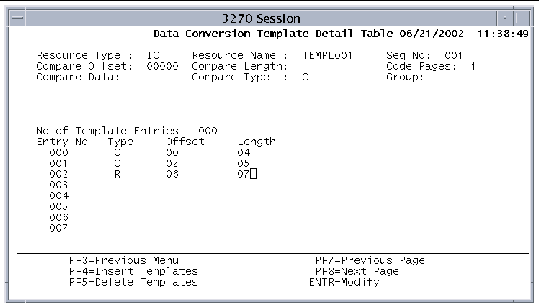
The conversion process converts the four-character field at offset 0 from the start of the record. The type R entry defines the repeating record, starting at offset 6. The length of the repeating field (KXT-OCC) is 7 bytes. The offset for all entries after a type R entry should be the offset from the start of the repeating field, not from the start of the record. The character data field (KXT-DATA) that is to be converted is at offset 2, in the repeating field.
At the end of the list of template entries, the conversion process adds the length of the repeating field to the current pointer and points to the next occurrence of this field. The process starts again at the first entry after the type R entry. This continues until there is no data in the record left to convert.
1. Press PF4 on the CVT screen to display the Insert screen.
2. Add new conversion templates and press Enter.
3. On the CVT screen, select a template and press PF9.
4. On the Details screen, define the conversion information and press Enter.
5. Repeat step 4 for each template you are defining.
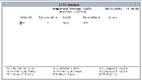
The Temporary Storage Table (TST) defines the storage and recovery of local and remote temporary storage queues. Display the TST by pressing PF10 on the Extended Tables menu.
Sun MTP writes all recoverable temporary storage queues as follows:
Records can also be written to the TEMPSTGR file whenever a transient data queue trigger occurs or when a START command with data (RTRANSID, RTERMID, QUEUE or FROM) is issued. When a START command with data is issued, Sun MTP looks up the entry for the queue in the TST. If the queue is recoverable, a record is written into the TEMPSTGR file, and the transaction is queued. When the transaction actually starts, Sun MTP deletes some information from the recovery record. This ensures that an asynchronous transaction that terminates abnormally does not abort during a system restart.
The TST contains the following information:
|
Generic queue name that contains one to eight characters of the temporary storage queue name. To protect Sun MTP temporary storage queues, a group entry of DF is used. |
|
|
One-character field that indicates whether or not the queue is recoverable. Y: Queue is recoverable if the Data-ID matches the first characters of the temporary storage queue name. |
|
|
Four-character field that specifies the system identifier for the remote system to be used for function shipping. |
|
|
Identifies the temporary storage queue as it is known on the remote system, if it is different from the local name. This field has a maximum length of eight characters and must be the same length as the Data-ID. Sun MTP substitutes this remote name before sending the function shipping request to the remote system. During the substitution, Sun MTP compares the Data-ID and the temporary storage queue name and appends any queue-specific characters to the RemoteName before it sends it to the remote system. For example, if the Data-ID is DFR, the RemoteName is ABC, and the queue name is DFR123, Sun MTP sends the queue name ABC123 to the remote system. |
|
|
Identifies the group specified in the Group Name field of the GCT. If a group name is specified in the GCT, this field contains that value. See Group Control Table (GCT). When you press the PF2 key on the TST screen, this entry is written to tst.tbl in the directory specified in the GCT Directory field, if the read-only indicator (R/O field) is set to No for this group. If the group field is blank, the entry is read or written to the tst.tbl file in the $KIXSYS directory. |
1. Press PF4 on the TST to display the Insert screen.
2. Add new temporary storage queues.
3. After you are finished, press Enter.
4. Save the table to the disk.
Copyright © 2004, Sun Microsystems, Inc. All rights reserved.