| C H A P T E R 3 |
|
Facility and System Requirements |
This chapter details the power and grounding requirements for Sun Fire 15K/12K systems.
To prevent catastrophic failures, the design of the power system must ensure that adequate power is provided to your Sun Fire 15K/12K systems. Sun Microsystems recommends that all power circuits supplying power to the Sun Fire 15K/12K systems be derived from dedicated electrical distribution panels. Electrical work and installations must comply with applicable local, state, or national electrical codes.

|
Caution - System earth fault protection relies on the building circuit. |
Sun Microsystems makes every effort to minimize the effects of power failures and interruptions to the hardware. Sun Fire 15K/12K systems have dual, redundant, current-sharing power supply inputs, and are designed to use two independent power sources. However, if the system is subjected to repeated power interruptions and fluctuations, it is susceptible to a higher component failure rate than it would be with a stable power source. Provide a stable power source, such as an uninterruptible power system (UPS), to reduce the possibility of component failures.
The power supplies of the Sun Fire 15K/12K systems incorporate an inrush current limitation after the first power on. The maximum inrush current is 55 amperes peak, during hot or cold start (after the AC has been removed for 60 seconds) and 35 amperes root mean square, hot or cold, when measured over one line cycle. The inrush current decays to its normal operating current in less than 200 milliseconds.
FIGURE 3-1 lists the electrical specifications for the system cabinet. Use TABLE 3-2 to record the power cable requirements (see Appendix A for an expanded form to use and retain for your records). TABLE 3-3 provides a summary of features of the three power configurations. FIGURE 3-1, FIGURE 3-2, and FIGURE 3-3 illustrate the possible system power connections.
Sun Fire 15K/12K systems can operate while one power supply is being serviced and with two independent power sources as in FIGURE 3-1 as long as the systems stay under 20,000W DC power consumption as measured by the SMS command
showenvironment -p powers.
Sun Fire 15K/12K systems equipped entirely with 300-1705 (A196) power supplies add the capability to operate while one power supply is being serviced above 20,000 W but not coincident with a loss of one power source. Sun Fire 15K/12K systems equipped entirely with 300-1813 (A211) power supplies add the capability to operate with 1950Mhz USIV+Uniboards.
Sun Fire 15K/12K systems configured as in FIGURE 3-3 cannot operate above 20,000W DC power consumption while one power supply is being serviced.
|
Redundant (FIGURE 3-1) |
||
|
High reliability (FIGURE 3-2) |
||
|
Basic (FIGURE 3-3) |
The Sun Fire 15K/12K systems achieve earth ground through the power cords. For this reason, a gounding cable is not provided with the system. The power cords have three prongs: two for current and one for ground. At the AC input module, the ground prong, and system chassis are connected. Final chassis ground is achieved when the power cord is connected to a receptacle, where the ground prong contacts the power receptacle. For successful grounding, the customer must provide properly grounded power receptacles so the power distribution unit (PDU) ground is earth ground.
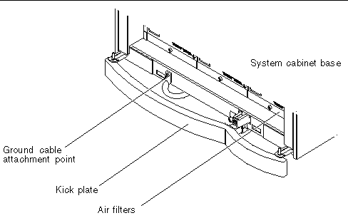
A ground cable may be affixed to the system. While not required, the additional ground point allows leakage current to dissipate more efficiently. It is important to note that power cords are grounded through the receptacle and the ground cable must reference a common earth ground. Otherwise, a difference in ground potential can be introduced.
Use the following procedures to properly ground the Sun Fire 15K/12K systems.
|
Note - You can use the A-series circuit breaker (Carlingswitch, part number: AF3-X0-06-184-X13-D, or equivalent) if a PDU is used between the Sun Fire 15K/12K systems and the facility power system. |
1. Ensure the customer has properly grounded PDUs in the data center. The PDU must be earth ground.
2. Ensure all grounding points (raised floors and power receptacles) reference PDU ground.
|
Note - The customer needs to procure the grounding cable. A grounding cable is not shipped with the system. |
3. Attach the ground cable to the system, behind the kick plate, at the bottom of the frame base as shown in FIGURE 3-4.

4. The ground cable attaching area might be a painted surface. Ensure metal-to-metal solid contact is made for this installation.
Copyright © 2007, Sun Microsystems, Inc. All Rights Reserved.