| C H A P T E R 3 |
|
Cooling and Air Distribution |
Maintenance of appropriate temperature and relative humidity (RH) levels in a data center environment is extremely important. Computer hardware requires a balanced and appropriate environment for optimal systems operations. Temperatures or RH levels outside the specified operating ranges, or extreme swings in conditions, can detrimentally affect component reliability. To complicate this, the heat load of most computer rooms is extremely complex and experiences normal fluctuations during its evolution. A great deal of importance must be placed on maintaining appropriate temperature and RH levels throughout the data center at all times. The information in this Chapter includes the following Sections:
An ambient temperature range of 70º to 74º F (21º C to 23º C) is optimal for system reliability and operator comfort levels. Most computer equipment can operate within a wide psychrometric range, but a temperature level near 72º F (22º C) is desirable because it is easier to maintain safe associated relative humidity levels at this temperature, and there is an acceptably wide operational buffer in case of environmental support systems down-time. Though individual standards vary slightly, 70º to 74º F (21º C to 23º C) should be used as an optimal recommendation.
Relative humidity is the amount of moisture in a given sample of air at a given temperature in relation to the maximum amount of moisture that a sample could contain at the same temperature. A volume of air at a given temperature can hold a certain amount of moisture. Because air is a gas, it expands as it is heated. As air gets warmer, its volume increases and the amount of moisture it can hold increases, thus causing its relative humidity to decrease. Therefore, in a system utilizing subfloor air distribution, the ambient relative humidity will always be lower than in the subfloor.
Ambient relative humidity levels between 45% and 50% RH are the most suitable for safe data processing operations. Under certain circumstances, most data processing equipment can operate within a fairly wide environmental range (20% to 80% RH), but the optimal goal should be specified at 45% to 50% RH for several reasons. The optimal range helps protect computer systems from corrosivity problems associated with high humidity levels. It also provides the greatest operating time buffer in the event of environmental control system failure. In addition, this range helps avoid failures or temporary malfunctions caused by intermittent interference from static discharges that occur when relative humidity is too low. Electrostatic discharge (ESD) is easily generated and less easily dissipated in areas where the relative humidity is below 35% RH, and becomes critical when levels drop below 30% RH. The 5% RH range may seem unreasonably tight when compared to the guidelines used in typical office environments or other loosely controlled areas, but it is not so difficult to maintain in a data center because of the high efficiency vapor barrier and low rate of air changes normally present
|
50º to 90º F (10º to 32º C)[1] |
|||
|
Altitude[2] |
Though the design limits for this hardware are wide, conditions should always be maintained near the optimal levels. It should also be noted that certain extremes within this range can lead to unacceptable conditions. If very high temperatures are maintained in conjunction with very high relative humidity conditions, condensation can occur. Also, if very low temperatures are maintained with very low relative humidity levels, even a slight rise in temperature can lead to unacceptably low relative humidity levels. The reliability and life expectancy of the hardware will be enhanced by maintaining conditions within the optimal ranges.
Temperature and relative humidity conditions should be maintained at levels that allow for the greatest operational buffer in case of environmental support equipment down-time. The goal levels for the computer room should be determined in a manner that will achieve the greatest operational buffer and the least possibility of negative influence. The specific hardware design, room configuration, environmental support equipment design and other influencing factors should be taken into consideration when determining the specific relative humidity control appropriate for a particular room. Psychrometrics can affect hardware through thermal influences, Electrostatic Discharge (ESD), and increases in environmental corrosivity.
Temperature conditions should be maintained as close to the optimal recommendation as possible. Near the limits of the temperature range, there is less of a buffer to absorb influences from actions in the room. The temperature profile can be dramatically affected by problems with the environmental support equipment, such as component failure or even scheduled preventive maintenance.
There is also less tolerance when the heat load of the room changes due to the installations, de-installation or reconfiguration of hardware. Significant changes in cooling temperature can also be caused by the removal of excessive numbers of floor tiles for subfloor work, such as cabling. Appropriate temperatures also make it easier to maintain appropriate moisture levels. Even if appropriate relative humidity levels can be maintained at high or low temperatures, it is likely that the actual moisture content, in grains of moisture, of the air would be inappropriate.
Another consideration is the generation and neutralization of static charges, as well as the effects such charges can have on sensitive electronics equipment, as well as some means of preventing such damage. Appropriate relative humidity levels help maintain an environment in which static charges are more easily dissipated. Please refer to Section 6.8 for additional information.
High humidity environments increase the corrosivity potential of gaseous contaminants in the atmosphere. Gases suspended in the air can be transferred to the room's hardware via the moisture in the air. It should also be noted that drastic changes in temperature can cause latent heat changes, leading to the formation of condensation. This is particularly common in areas where hot and cold air meet. Excessive moisture in the air and condensation can cause a number of hardware problems. Water can react directly with metals, attacking them and forming corrosion. Another way that a moist atmosphere can degrade hardware is by forming conductive solutions (electrochemically). If there are electrical potential differences between two dissimilar metals in a component, electrolytic or galvanic corrosion processes can set in. The water can also form a more reactive combination with gases present in the atmosphere. The resultant compounds can then attack the hardware surfaces. Excessively high RH levels should be avoided.
Accurate and comprehensive monitoring of environmental support equipment and in-room conditions is extremely important in an environment as complex and sensitive as a data center. The monitoring system used must effectively assess the room conditions, or it will provide an inaccurate representation that can lead to inappropriate actions or ill-founded assumptions. The following considerations should be addressed
While an added expense to the design and maintenance of a facility, comprehensive monitoring systems provide an invaluable tool to building maintenance personnel. They are essential in correcting current problems in an expedient manner and identifying potential susceptibilities before they impact hardware operations.
While the specific details of the environmental support systems will vary from site-to-site, an air conditioning system with a downward flow should be utilized in all designed computer rooms. Appropriate conditions can be maintained for a small amount of hardware space utilizing other designs, but the air-flow patterns associated with the downward flow design allow for the most efficient cooling of the hardware. The data center should not be designed based on the same school of thought used in general comfort cooling applications. The efficiency of a precision air conditioning system is not only measured by the degree of temperature control, but also on the ability of the system to get the conditioned air to the units of hardware in need of cooling. Computer rooms require precision cooling for a number of reasons:
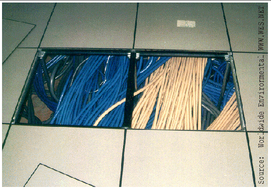
The downward-flow air conditioning system typically utilized in data centers and other similar environments incorporates a raised floor system. The raised floor should be 24 inches (60cm) with a minimum of 18 inches (47 cm) above the structural deck to allow for both the running of cables and pipes as well as for the distribution of conditioned air to the hardware. The modular tile design allows for ease of movement for both hardware and air distribution reconfigurations. As hardware is added, solid tiles are replaced by tiles with cut-outs to allow cable access, and perforated tiles are positioned to deliver conditioned air to the hardware intakes.
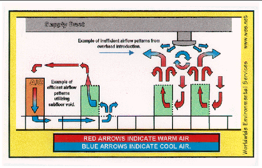
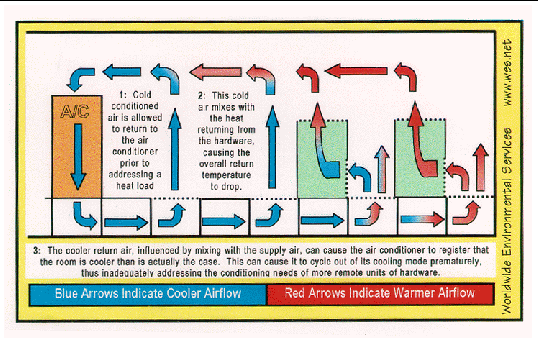
In the general airflow patterns associated with most computer room process coolers, room air enters the top of the air conditioner (Return Air) where it is cleaned by air filter banks. As the return air passes over the cooling coil, the air temperature is lowered significantly, and large fans at the bottom of the unit push the conditioned air (Supply Air) into the room's subfloor void where it is introduced into the computer space via cable cutouts, floor grilles or perforated floor tiles. Once in the ambient room space, the conditioned air mixes with the hardware heat load and flows back to the air conditioners for reconditioning. This produces an efficient airflow pattern.
Centralized systems, using a single large air handling unit, should be avoided. Whether the system introduces the conditioned air into the subfloor, or directly into the hardware space, centralized systems generally lack the redundancy present with individual packaged units. Centralized systems also lack the degree of control present with multiple units. In most centralized systems, the temperature and relative humidity are regulated by a single sensor set in the ambient space of the room, or in the return air duct. This can give an inaccurate representation of room conditions, as it is unlikely that conditions in all areas are the same as they are at this single sensor point.
Overhead air introduction or upflow air conditioning should be avoided due to their associated turbulent airflow patterns. The majority of the hardware in most rooms takes in air for cooling at the front or bottom of the unit ad exhausts it out the back or top. Introducing conditioned air from the ceiling level causes turbulence as the conditioned air meets the hot exhaust.
It is extremely important that the hardware in the room be taken into consideration in order to ensure that the air conditioners have adequate control over cooling and heating cycles. Hardware units that rely on direct subfloor cooling are particularly susceptible to large swings in temperature associated with direct expansion air conditioners that have only two or four stages of cooling. Because the regulation of the air conditioners is controlled by sensors in the return airflow, there is a delay in response that can cause significant fluctuations in conditions. Chilled water systems with modulated controls are more appropriate where temperature fluctuations are a significant concern.
Humidification can take place within the in-room packaged air conditioners, or it can be provided by stand-alone units mounted within the room. While ordering the humidifiers as a feature of the air conditioner may be more convenient, a moisture introduction directly into the warmer ambient air is preferable to an introduction into the cold supply air within the enclosed air conditioner. The following considerations should be taken into account when determining the design of the system.
One recommended humidification system design utilizes a closed water bottle that contains electrodes to quickly heat the contained water and produce steam. These units can be installed within the actual room space as well as inside the air conditioners. The closed bottle design removes any suspended particles from the supply water, resulting in a clean moisture supply. If properly designed and maintained, alternate designs, such as ultrasonic humidifiers, can be utilized effectively. Building steam systems distributed by a central air conditioner should not be used. These do not have the flexibility available from multiple in-room units. As with the air conditioning, the use of multiple humidifiers provides localized control or redundancy.
The set points of the environmental support equipment may vary between sites, and even between individual units at the same site. One of the advantages of multiple packaged units is the ability to modify set-points in localized areas. The hardware heatload in a room may vary from dense placement of hardware with high heat generation to open areas with little or no hardware. While the main means of addressing such variances is with adjustments to the air distribution tile placement, minor adjustments to the air conditioner or humidifier set-points may also be necessary.
Under most circumstances, air conditioners should be set at 72º F (22º C) with a sensitivity range of +/- 2º F (+/-1º C). Humidifiers, in most cases, should be set at 48% RH with a sensitivity range of +/- 3% RH. The set-points of the air conditioners should always be chosen in an effort to maintain the optimal recommended temperature and relative humidity levels for the room environment. These set points should maintain appropriate conditions, while allowing wide enough sensitivity ranges to help avoid frequent cycling of the units. While these tight ranges would be difficult to maintain in a loosely controlled office environment, they should be easily attained in a controlled data center.
Numerous factors, such as heat-load and vapor barrier integrity, will influence the actual set-points. If the room lacks adequate vapor barrier protection, for instance, it may be necessary to adjust humidifier set points to accommodate seasonal influences. Ideally, all inappropriate influences on the data center environment will be eliminated, but in the event that they are not, minor adjustments, made by trained personnel, can help alleviate their effects on the environment.
The specific design of the mechanical support systems will be dependent upon the type of cooling system chosen. Numerous factors will go into the decision as to whether to use direct expansion compressorized air conditioners or a chilled water system. The specific requirements of the hardware to be cooled should be taken into consideration when determining the type of air conditioning system.
The availability of space to house large chillers, cooling towers, and piping systems associated with chilled water designs must be considered. Direct expansion units require ground-level or roof space to house large condensers. The climate of the environment in which the building is located is also a governing factor, as certain designs may be easier or less expensive in certain climates. Issues of flexibility and redundancy should also be evaluated. The system installed should provide adequate flexibility for growth, and 100% redundancy. The loss of any one component of the system should not have a significant impact on the system as a whole. The system should be designed in such a fashion so as to accommodate repairs or changes while the system is on-line, or with minimal downtime.
The system should be designed in such a manner so as minimize the opportunity for leaks of cooling water or refrigerants within the computer room controlled zone. Piping should not be run in the ceiling void of the room. It is also extremely important that air conditioner piping is not run directly in front of the air conditioner discharges. Multiple taps should be designed into chilled water piping to facilitate changes in configurations.
The mechanical support systems should be connected to the building monitoring system. Status and critical alarms should be recorded. This system should also monitor the in-room air conditioners and conditions throughout the subject areas.
Perforated floor tiles are the supply diffusers of a downward flow air conditioning system. The modular design of the tiles allows for the flexibility necessary in a complex data center environment. The number and type of tiles for each particular site will depend on the specific characteristics of the site. The following guidelines should, however, be considered in the determination.
The following recommendations are based on the basic front-to-back air-flow cabinets used by most Sun Microsystems equipment. The installation documentation for the hardware being installed should be consulted prior to installation. The specific hardware in place in the various subject areas of the facility must be taken into consideration when assessing the environment. The density and complexity of the heat load can offer many challenging problems. The necessity of maintaining appropriate conditions in a mainframe environment are universally understood, but environmental conditions in server areas are often overlooked. The heat load of small, individual servers or storage arrays is generally low, but when these units are stacked in cabinets, the density of the heat load increases dramatically. In addition, the newer technologies utilize denser geometries in their internal components than many older ones. In many instances, large server rooms can have a much higher heat load than traditional mainframe rooms.
The philosophy used when addressing the needs of a single server or storage array cabinet may no longer apply when large numbers of these cabinets are grouped together. Simply multiplying the needs of the one to determine the needs of the group will often overlook important factors. The interactions must also be taken into account. How the units are placed in relation to one another can have a significant impact on heatload concentration, conditioned air distribution and service accessibility. While a single unit may be very tolerant, as its needs are more easily met, a large group requires a great deal of thought and planning to properly accommodate, and continued vigilance to properly maintain.
Many studies have been conducted regarding the changing trends in technology. There is no question that the same computing power can now be achieved with equipment taking up a fraction of the floor space previously needed. Thus, a comparison of computing or storage capacity versus heat load will indicate a significant decrease in heat load in recent years since far less equipment is needed for the same data capacity. What this comparison does not indicate, however, is that while you now need less equipment to do the same things, the heat load per square foot is much denser. Thus, if you fill the same amount of floor space with new equipment, you will have much more computing power, but you will also often have a much higher or more concentrated heat load.
The majority of Sun racks are designed to take in conditioned supply air in the front, pass it over the heat-loads of the internal components, and exhaust it from the rear. These racks house a wide variety of components with differing designs. Some components utilize airflow patterns that go from bottom to top, some go from front to back, and some go from one side to the other. In each of these instances, the cabinet converts the airflow pattern to a front-to-back or front-to-top design. This allows for ease of planning in that it is not necessary to accommodate multiple airflow designs. The cabinet provides a generally uniform design.
Because of the front-to-back air-flow patterns, the ideal placement would have the units installed face-to-face (and back-to-back) as illustrated in FIGURE 3-4. By configuring the units in this fashion, direct transfer of the hot exhaust of one unit into the intake of another is eliminated. If the aisle width is maintained at the appropriate width of 4 feet (1.22 meters), in this scenario, the side-to-side spacing between racks can be reduced virtually to zero. Enough clearance should be maintained to allow any rack within that lineup to be removed for service or replacement. This is possible because the side panels of the Sun cabinets are solid, and not used for air flow. If all air conditioning considerations are appropriately addressed, the aisles between the exhausts can be made as narrow as 3 ft. (0.9 m). If the units are placed closely together, it is recommended that no more than five (5) cabinets be grouped before a minimum of 1 1/2 feet (.46 m) is left for access to their rear, or between aisles.
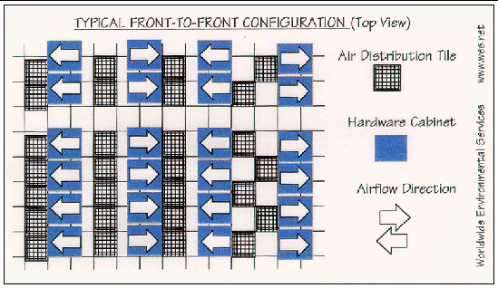
If, for some reason, the units must be installed all facing in the same direction (not recommended), it is important that adequate space be left between the aisles to avoid the direct transfer of the heated air from the exhaust of one unit into the intake of another as illustrated in FIGURE 3-5. This can be accomplished by allowing adequate space between the units and the aisles. The amount of space necessary will be dependent on numerous factors in the room. Assuming that there is adequate air conditioning, and that it is being efficiently distributed, 4 feet (1.22 meters) should be enough space for the aisles. In some instances, where conditioned air distribution is less than optimal, wider aisles may be necessary. If the width of the aisles is less than this recommendation, it is advised that there be a minimum of 1 ft. (0.3 m) between the units to help spread out the heat load.
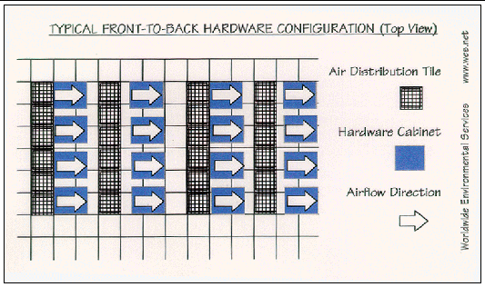
It is important to remember that the many aspects of the computer room environment are interconnected. Changes to one aspect will, in turn, affect others. Along the same lines, implementing one change in isolation may produce undesirable results. The overall effects on the environment of the room must be taken into consideration. In either scenario, the following considerations must be taken into account:
It should be noted that the preceding recommendations are for hardware installed in Sun Microsystems cabinets. Components installed outside of these cabinets may have very different requirements. Components with a side-to-side air-flow pattern are converted to front-to-back air flow by the Sun Cabinets. If these components are installed outside of these cabinets, it is important that they not be placed closely next to each other, as the exhaust of one unit will enter the intake of the next, leading to very high temperatures down the line. For these same reason, it is extremely important that the units are not installed in after market or custom cabinets without first consulting and gaining approval from your Sun Microsystems representative.
It is not enough for appropriate return air temperature to be maintained by the air conditioning system, the conditioned air must also be efficiently transferred to the areas of the room in need of conditioning. If the conditioned air provided by the environmental control equipment is not delivered to the hardware properly, the air conditioning system is not performing efficiently. Because the subfloor void acts as a duct, with the air distribution tiles and cable cut-outs acting to distribute the conditioned air, an adequate subfloor pressure is necessary in order to deliver the cooled air. If the subfloor pressure is too low, the conditioned air will not be forced to the areas of the room in need of cooling. Air conditioner manufacturers normally recommend the appropriate free area in the form of air distribution grilles and perforated floor panels.
Ideally, the positive pressurization of the subfloor void in relation to the above-floor hardware space should be maintained at or near the optimal recommendation of 0.05 in wg. Subfloor pressurization should not be allowed to fall below the minimum recommendation of 0.02 in wg. Designed airflow velocity (FPM), breaches in the supply plenum, perforated tile and cable cut-out size and number and hardware design will all influence pressurization. It is important that the pressurization across the room is periodically checked to ensure that conditions remain appropriate. While pressurization will generally equalize across the supply plenum, conditions can vary significantly across a large room, as influences such as air conditioner or perforated tile placement cause pressure to build-up or dissipate. In addition, it is extremely important that subfloor pressure conditions are monitored any time subfloor work is taking place. Each solid tile represents 4 ft2 of floor area. This is equivalent to four typical perforated tiles (with a 25% perforation). Lifting four solid tiles is roughly equivalent to the recommended free area (in the form of perforated tiles) for a typical 24 ton direct expansion air conditioner. Removing excessive numbers of tiles can have a dramatic effect on air distribution in a room.
The subfloor void in a downward-flow air conditioning system is a supply plenum in the air distribution system. The conditioned air traveling to the hardware passes through the air conditioners, into this plenum, and then through perforated tiles and into the room space. By introducing more air into the plenum than is allowed to escape, a positive pressurization of the subfloor void is achieved. This pressurization is essential to the efficient cooling of the hardware. If the subfloor pressure is inadequate, the conditioned air will not be effectively pushed to the areas of hardware in need of cooling.
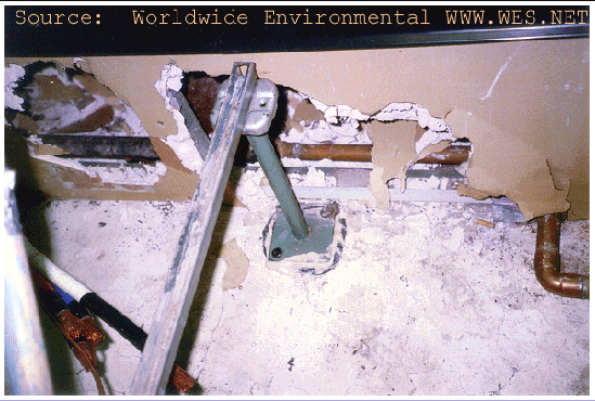
A superior vapor barrier is essential in maintaining adequate controllability over in-room conditions. Any significant breaches in the vapor seal of the room will expose the computer room controlled area to potentially disruptive influences.
The first line of defense is the exterior shell of the building. Most modern buildings are normally constructed with at least a minimal designed protection against moisture migration. This is normally intended to protect the building structure itself as well as to make the environmental support more energy efficient. Because of the more stringent environmental requirements in the data center, it is normally necessary to incorporate additional vapor barrier protection into the perimeter of the controlled areas. Failure to protect against outside influences could over-tax the environmental support equipment, and could lead to inappropriate conditions within the controlled environment. The following points will help provide an effective barrier against moisture migration.
Proper implementation of these precautions will help protect against inappropriate or potentially damaging influences.
Copyright © 2002, Sun Microsystems, Inc. All rights reserved.