Parts of the Internal Virtual Network
An internal virtual network built on the Solaris OS contains the following parts:
-
At least one network interface card, or NIC.
-
A virtual NIC, or VNIC, which is configured on top of the network interface
-
A virtual switch, which is configured at the same time as the first VNIC on the interface.
-
A container, such as a zone or virtual machine , which is configured on top of the VNIC.
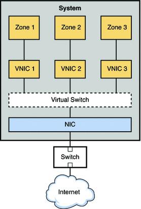
The next figure shows these parts and how they fit together on a single system.
Figure 9–1 VNIC Configuration for a Single Interface

The figure shows a single system with one NIC. The NIC is configured with three VNICs. Each VNIC supports a single zone. Therefore, Zone 1, Zone 2, and Zone 3 are configured over VNIC 1, VNIC 2, and VNIC 3, respectfully. The three VNICs are virtually connected to one virtual switch. This switch provides the connection between the VNICs and the physical NIC upon which the VNICs are built. The physical interface provides the system with its external network connection.
Alternatively, you can create a virtual network based on the etherstub. Etherstubs are purely software and do not require a network interface as the basis for the virtual network.
A VNIC is a virtual network device with the same data-link interface as a physical interface. You configure VNICs on top of a physical interface. For the current list of physical interfaces that support VNICs, refer to the Network Virtualization and Resource Control FAQ. You can configure up to 900 VNICs on a single physical interface. When VNICs are configured, they behave like physical NICs. In addition, the system's resources treat VNICs as if they were physical NICs.
Each VNIC is implicitly connected to a virtual switch that corresponds to the physical interface. The virtual switch provides the same connectivity between VNICs on a virtual network that switch hardware provides for the systems connected to a switch's ports.
In accordance with Ethernet design, if a switch port receives an outgoing packet from the host connected to that port, that packet cannot go to a destination on the same port. This design is a drawback for systems that are configured with zones or virtual machines. Without network virtualization, outgoing packets from a virtual machine or a zone with an exclusive stack cannot be passed to another virtual machine or zone on the same system. The outgoing packets go through a switch port out onto the external network. The incoming packets cannot reach their destination zone or virtual machine because the packets cannot return through the same port as they were sent. Therefore, when virtual machines and zones on the same system need to communicate, a data path between the containers must open on the local machine. Virtual switches provide these containers with the method to pass packets.
How Data Travels Through a Virtual Network
Figure 9–1 illustrates a simple VNIC configuration for a virtual network on a single system.
When the virtual network is configured, a zone sends traffic to an external host in the same fashion as a system without a virtual network. Traffic flows from the zone, through the VNIC to the virtual switch, and then to the physical interface, which sends the data out onto the network.
But what happens if one zone on a virtual network wants to send packets to another zone on the virtual network, given the previously mentioned Ethernet restrictions? As shown in Figure 9–1, suppose Zone 1 needs to send traffic to Zone 3? In this case packets pass from Zone 1 through its dedicated VNIC 1. The traffic then flows through the virtual switch to VNIC 3. VNIC 3 then passes the traffic to Zone 3. The traffic never leaves the system, and therefore never violates the Ethernet restrictions.
- © 2010, Oracle Corporation and/or its affiliates
