Chapter 10 Planning for Network Virtualization and Resource Control
This chapter contains information and example scenarios to help you evaluate and then design network virtualization and resource control solutions for your site. The chapter discusses the following scenarios:
Each scenario contains “best usage” suggestions that explain the types of networks that best benefit from the particular scenario.
Network Virtualization and Resource Control Task Map
|
Task |
Description |
For Instructions |
|---|---|---|
|
Design and plan a virtual network on a single host |
Consolidate network services and applications offered by the local network onto a single host. This scenario is especially useful for consolidators and service providers. | |
|
Design and plan for a private virtual network on a single host |
Run a virtual network that does not allow public access. This scenario is recommended for system administrators who need to run a development environment. | |
|
Provide bandwidth management and resource control for systems on a per-interface basis. |
Isolate, prioritize, and assign a specific amount of interface bandwidth for packet traffic. This scenario is useful for systems that handle heavy traffic for particular services, such as a web service or a database server. | |
|
Provide bandwidth management and resource control for a virtual network |
Create a scenario to isolate, control, and prioritize traffic for particular applications on the individual containers of the virtual network. This scenario is particularly useful for service providers who bill customers for usage of particular application or who rent out containers to customers. |
Information to come |
Planning and Designing a Virtual Network
This section describes two different scenarios for configuring a virtual network. Look over the scenarios to help determine which most closely fits the needs of your site. Then use that scenario as the basis for designing your specific virtualization solution. The scenarios include:
-
Basic virtual network of two zones, especially useful for consolidating network services from the local network onto a single host.
-
Private virtual network, useful for a development environment where you isolate applications and services from the public network.
Basic Virtual Network on a Single System
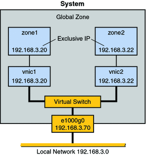
Figure 10–1 shows the basic virtual network, or “network in a box” that is used in examples throughout the section Configuring a Basic Virtual Network.
Figure 10–1 Virtual Network on a Single Host

This virtual network consists of the following:
-
A single GLDv3 network interface e1000g0. This interface connects to the public network 192.168.3.0/24. Interface e1000g0 has the IP address 192.168.3.70.
-
A virtual switch, which is automatically configured when you create the first VNIC.
-
Two VNICs. vnic1 has the IP address 192.168.3.20, and vnic2 has the IP address 192.168.3.22.
-
Two exclusive IP zones. zone1 is configured over vnic1, and zone2 is configured over vnic2.
Note –Though the example uses exclusive IP zones, you can also use other types of virtual machines such as LDOMS in this scenario.
The VNICs and zones in this configuration allow access to the public. Therefore, the zones can pass traffic beyond the e1000g0 interface. Likewise, users on external networks can reach applications and services offered by the zones.
Best Uses for the Basic Virtual Network
The network in a box scenario enables you to isolate processes and applications into individual virtual machines or zones on a single host. Furthermore, this scenario is expandable to include many containers, each of which could run a completely isolated set of applications. The scenario improves a system's efficiency and, by extension, the efficiency of the local network. Therefore, this scenario is ideal for the following users:
-
Network consolidators and others who want to consolidate the services of a LAN onto a single system.
-
Any site that rents out services to customers. You can rent out individual zones or virtual machines, observe traffic, and take statistics for performance measuring or for billing purposes on each zone in the virtual network.
-
Any administrator who wants to isolate processes and applications to separate containers to improve system efficiency .
For More Information
-
For tasks that implement the basic virtual network, go to Configuring a Basic Virtual Network.
-
For examples that show how to configure the virtual network shown in this section, go to Configuring a Basic Virtual Network.
-
For conceptual information about VNICs and virtual networks, go to Network Virtualization and Virtual Networks.
-
For conceptual information about zones, go to Chapter 16, Introduction to Solaris Zones, in System Administration Guide: Virtualization Using the Solaris Operating System.
Private Virtual Network on a Single System
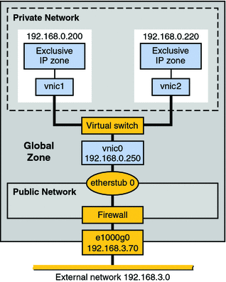
Figure 10–2 shows a single system with a private network behind packet filtering software that performs network address translation (NAT). This figure illustrates the scenario that is built in Example 11–7.
Figure 10–2 Private Virtual Network on a Single Host

The topology features a single system with a public network, including a firewall, and a private network built on an etherstub pseudo-interface. The public network runs in the global zone and consists of the following elements:
-
GLDv3 network interface e1000g0 with the IP address 192.168.3.70.
-
A firewall implemented in the IP Filter software. For an introduction to IP Filter, refer to Introduction to Solaris IP Filter in System Administration Guide: IP Services.
-
etherstub0, a pseudo-interface upon which the virtual network topology is built. Etherstubs provide the ability to create a virtual network on a host. That network is totally isolated from the external network.
The private network consists of the following elements:
-
A virtual switch which provides packet forwarding among the VNICs of the private network.
-
vnic0, which is the VNIC for the global zone, and has the IP address 192.168.0.250.
-
vnic1 with the IP address 192.168.0.200 and vnic2 with the IP address 192.168.0.220. All three VNICs are configured over etherstub0.
-
zone1, which is configured over vnic1, and zone2, which is configured over vnic2.
Best Uses for a Private Virtual Network
Consider creating a private virtual network for a host that is used in a development environment. Using the etherstub framework, you can totally isolate software or features under development to the containers of the private network. Moreover, you can use firewalling software for network address translation of outgoing packets that originate in the containers of the private network. The private network is a smaller version of the eventual deployment environment.
For More Information
-
For tasks for implementing the private virtual network, go to Configuring a Private Virtual Network
-
For the example that shows how to configure the private virtual network shown in this section, go toExample 11–7.
-
For conceptual information about VNICs and virtual networks, go to Network Virtualization and Virtual Networks.
-
For conceptual information about zones, go to Chapter 16, Introduction to Solaris Zones, in System Administration Guide: Virtualization Using the Solaris Operating System.
-
For information about Solaris IP Filter, go to Introduction to Solaris IP Filter in System Administration Guide: IP Services.
Network Interface-Based Flow Control
This section contains scenarios for using interface-based flow control. Flow control incorporates resource control and bandwidth management. This process involves organizing packet traffic into flows of related applications, and then assigning portions of an interface's overall bandwidth to the individual flows. You can also assign a specific application's traffic to a flow to isolate the traffic without assigning the flow an amount of bandwidth. Isolating particular types of traffic to flows makes the traffic more easily observed, evaluated, and possibly billed. The following scenarios are described:
Look over these scenarios to see which is most applicable for your site. For the tasks that implementing these scenarios, refer to Chapter 13, Configuring Resource Management on an Interface.
Interface-based Resource Control for a Traditional Network
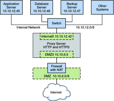
Figure 10–3 shows the network topology for a small business that needs to manage the bandwidth on its proxy server. The proxy server offers a public web site as well as a proxy for internal clients that require services from various servers on the site's internal network.
Note –
This scenario does not show how to configure flow control for a virtual network, and consequentially does not include VNICs. For flow control on a virtual network, refer to Flow Control for a Virtual Network.
Figure 10–3 Resource Control for a Proxy Server on a Traditional Network

The figure shows that the company has a public network, 10.10.6.0/8, that also serves as a demilitarized zone (DMZ). A system on the DMZ provides name-to-address translation (NAT) through an IP Filter firewall. The company has a large system that functions as the proxy server. The system has two wired interfaces and 16 processor sets with IDs 0–16. This system is connected to the public network through the interface nge0, with IP address l0 10.6.5. The link name for the interface is DMZ0. Through DMZ0, the proxy server offers HTTP and HTTPS service through the company's public web site.
The figure also illustrates the company's internal network, 10.10.12.0/24. The proxy server connects to the internal 10.10.12.0/8 network through interface nge1, with the IP address 10.10.12.42. The link name for this interface is internal0. Through the internal0 data link, the proxy server operates on behalf of internal clients that request the services of an application server, 10.10.12.45, database server, 10.10.12.46, and backup server, 10.10.12.47.
Best Use of Interface–based Resource Control on a Traditional Network
Consider establishing flow control for heavily used systems, especially those with newer GLD.v3 interfaces with large amounts of available bandwidth. Interface-based flow control improves the efficiency of the interface, the system, and potentially the network. You can apply flow control to any system on any type of network. Furthermore, if your goal is to improve network efficiency, you can separate various services into individual flows. This action assigns separate hardware and software resources to the individual flows, thus isolating them from other services on a particular system. After you establish flows, you can observe traffic for each flow and gather statistics. Thereafter, you can assign bandwidth amount and priorities to control usage on the interfaces.
For More Information
-
For tasks for implementing flow control, refer to Chapter 13, Configuring Resource Management on an Interface
-
For conceptual information about bandwidth management and resource control, refer to What Is Resource Control?
-
For detailed technical information, refer to the dladm(1M) and flowadm(1M)man pages.
Flow Control for the Virtual Network
This scenario shows how flow control is used within a virtual network, such as the basic virtual network that is introduced in Basic Virtual Network on a Single System.
Figure 10–4 Basic Virtual Network With Flow Controls

The topology is described in Basic Virtual Network on a Single System. Here a host has one network interface, e1000g0, with two VNICs, vnic1 and vnic2. zone1 is configured over vnic1, and zone2 is configured over vnic2. Resource management for the virtual network involves creating flows on a per-VNIC basis. These flows define and isolate packets with similar characteristics, such as port number or IP address of the sending host. You assign bandwidth based on the usage policy for the system.
Another very common usage for flow controls on VNIC traffic is by companies that rent out zones. You create different service level agreements for customers, and rent out zones with a guaranteed amount of bandwidth. When you create flows on a per-zone basis, you can isolate and observe each customer's traffic and monitor bandwidth usage. If your service level agreement is based strictly on usage, you can use Solaris statistics and accounting features to bill customers.
Flow controls are effective for any network that requires bandwidth management for traffic over zones. Larger organizations, such as application service providers (ASPs) or Internet service providers (ISP), can take advantage of resource control for VNICs for data centers and for multiprocessor systems. The individual zones can be rented out to customers for different levels of service. Therefore, you could rent out zone1 at the standard price and offer a standard bandwidth. Then, you could rent out zone2 at a premium price and give that customer a high level of bandwidth.
 How to Create a Usage Policy for Applications
on a Virtual Network
-
List the applications that you want to run on the host.
-
Determine which applications have historically used the most bandwidth or require the most bandwidth.
For example, the telnet application might not consume huge amounts of bandwidth on your system, but it could be heavily used. Conversely, database applications consume a huge amount of bandwidth, but might only be used on a sporadic basis. Consider monitoring traffic for these applications prior to assigning them to zones. You can use the statistical option of the dladm show-link command to gather statistics, as described in Gathering Usage Statistics for VNICs and Flows.
-
Assign these applications to separate zones.
-
Create flows for any application running in zone1 whose traffic you want to isolate and control.
-
Assign bandwidth to flows based on usage policies in place for your site.
 How to Create a Service Level Agreement for
the Virtual Network
-
Design a policy that offers different levels of services at different prices.
For example, you might create a basic, superior, and high levels of service, and price each level accordingly.
-
Decide whether you want to charge customers on a monthly, per service level basis, or charge customers on an actual bandwidth consumed basis.
If you choose the latter pricing structure, you need to gather statistics on each customer's usage.
-
Create a virtual network on a host, with containers for each customer.
A very common implementation is to give each customer their own zone running over a VNIC.
-
Create flows that isolate traffic for each zone.
To isolate all traffic for the zone, you use the IP address that is assigned to the zone's VNIC.
-
Assign bandwidth to each VNIC based on the service level purchased by the customer assigned to that VNIC's zone.
- © 2010, Oracle Corporation and/or its affiliates
