What to Do
-
Remove the main logic board from its antistatic packaging and place it on an antistatic mat.
Retain the packaging and use it to pack and return the defective board.
-
Set the jumpers on the replacement main logic board so that they are the same as the settings on the old board.
See "About the Main Logic Board Jumpers" for more information about jumper locations and settings.
-
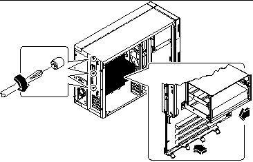
Position the board inside the chassis.
Align the notches at the top and bottom edges of the board with the corresponding tabs on the chassis wall.
Figure 6-4

-
Press the main logic board against the chassis wall as you slide it toward the rear panel.
-
Tighten the three captive screws securing the main logic board to the rear panel.
-
Reconnect the internal cables to the main logic board:
-
Reconnect any external cables to the rear panel of the system.
See "Locating Rear Panel Features".
Note -When the side access panel is removed, the system power interlock switches are activated. This safety mechanism prevents any DC voltages (except 5V standby power) from reaching the main logic board while the side access panel is removed.
- © 2010, Oracle Corporation and/or its affiliates
