Chapter 6 Removing and Installing Main Logic Board Components
This chapter describes how to remove and install the main logic board components within the system. For a list of part numbers for field-replaceable units and optional equipment, see "Illustrated Parts Breakdown".
Tasks covered in this chapter include:
How to Remove the Main Logic Board
This procedure must be performed by a qualified service-trained maintenance provider. Persons who remove any of the outer panels to access this equipment must observe all safety precautions and comply with skill level requirements, certification, and all applicable local and national laws.
Before You Begin
Before you remove the main logic board, you must remove all removable components from it, so that you can transfer them to the new main logic board after you install it. Complete these tasks to remove the necessary components:
Video Demonstration
Figure 6-1

Click on the icon above for a video demonstration.
Click here for Appendix E, Video Player Help.
What to Do
-
Disconnect any external cables attached to the rear panel of the system.
Be sure to note where each cable attaches to the rear panel. See "Locating Rear Panel Features".
-
Disconnect the internal cables from the main logic board.
Press the tab on the cable connector to detach each cable.
-
Loosen the three captive screws securing the main logic board to the rear panel.
Figure 6-2
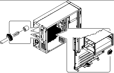
Note -Be sure to remove the SSP paddle card and all PCI cards prior to removing the main logic board. See "Before You Begin".
-
Slide the main logic board away from the rear panel until it is free.
-
Pull the bottom edge of the main logic board away from the machine, and lift the board out of the system.
Place the main logic board on an antistatic mat.
What Next
To replace the main logic board, complete this task:
How to Install the Main Logic Board
This procedure must be performed by a qualified service-trained maintenance provider. Persons who remove any of the outer panels to access this equipment must observe all safety precautions and comply with skill level requirements, certification, and all applicable local and national laws.
Before You Begin
You must remove all removable components from the old main logic board so that you can transfer them to the replacement board. For more information, see:
Note -
Be sure to remove the NVRAM/TOD module from the old main logic board so that you can transfer it to the replacement board.
Video Demonstration
Figure 6-3

Click on the icon above for a video demonstration.
Click here for Appendix E, Video Player Help.
What to Do
-
Remove the main logic board from its antistatic packaging and place it on an antistatic mat.
Retain the packaging and use it to pack and return the defective board.
-
Set the jumpers on the replacement main logic board so that they are the same as the settings on the old board.
See "About the Main Logic Board Jumpers" for more information about jumper locations and settings.
-
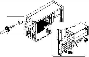
Position the board inside the chassis.
Align the notches at the top and bottom edges of the board with the corresponding tabs on the chassis wall.
Figure 6-4
-
Press the main logic board against the chassis wall as you slide it toward the rear panel.
-
Tighten the three captive screws securing the main logic board to the rear panel.
-
Reconnect the internal cables to the main logic board:
-
Reconnect any external cables to the rear panel of the system.
See "Locating Rear Panel Features".
Note -When the side access panel is removed, the system power interlock switches are activated. This safety mechanism prevents any DC voltages (except 5V standby power) from reaching the main logic board while the side access panel is removed.
What Next
Remove the NVRAM module from the replacement board and install it on the old board for return to Sun Microsystems. See "How to Install the NVRAM/TOD Module".
Complete these tasks to transfer the components that you removed from the old main logic board to the new board:
Complete this task to reassemble the system:
When you are ready to restart the system, be sure to run POST and OpenBoot Diagnostic tests to verify that the system functions correctly with the new parts you have just installed. For additional information, see Chapter 12, Diagnostics and Troubleshooting.
Note -
After installing the new main logic board, you must restore Remote System Control (RSC) configuration parameters before you can use RSC. During RSC configuration, RSC parameters are typically backed up to a hard disk drive. You must restore those parameters to the RSC SEEPROM on the new main logic board. For additional details, see the Remote System Control (RSC) User's Guide.
How to Remove a Memory Module
Before You Begin
Complete these tasks:
Dual inline memory modules (DIMMs) are made of electronic components that are extremely sensitive to static electricity. Static from your clothes or work environment can destroy the modules. Do not remove any DIMM from its antistatic packaging until you are ready to install it on the main logic board. Handle the modules only by their edges. Do not touch the components or any metal parts. Always wear a grounding strap when you handle the modules.
What to Do
-
Locate the DIMM module you want to remove on the main logic board.
See "About Memory".
-
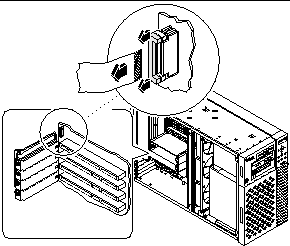
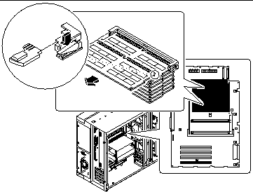
Push the ejection lever away from the memory module and eject it from the socket.
Figure 6-5
-
Grasp the top corners of the memory module and pull it out of its socket.
Place the module on an antistatic mat.
What Next
To replace a memory module, complete this task:
How to Install a Memory Module
Before You Begin
Dual inline memory modules (DIMMs) are made of electronic components that are extremely sensitive to static electricity. Static from your clothes or work environment can destroy the modules. Do not remove any DIMM from its antistatic packaging until you are ready to install it on the main logic board. Handle the modules only by their edges. Do not touch the components or any metal parts. Always wear a grounding strap when you handle the modules.
Complete these tasks:
For information about memory configuration, see "About Memory".
What to Do
-
Remove the new memory module from its antistatic packaging.
-
Locate the socket into which you will install the module.
See "About Memory".
Note -
Each bank used must contain four modules of equal capacity (for example, four 32-Mbyte memory modules, four 64-Mbyte modules) to function properly. Do not mix capacities within the same bank. See "About Memory".
-
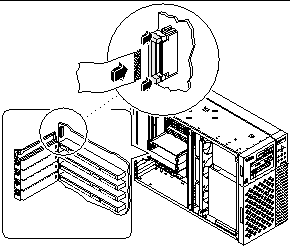
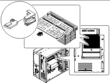
Orient the module so that the small notch on the bottom corner of the module is at the same end as the socket's ejection lever.
Figure 6-6
-
Align the module with its socket until it contacts the socket evenly along the socket's length.
-
Push firmly down on both ends of the module until the bottom edge is firmly seated in the socket.
Ensure that all module contacts engage in the socket.
What Next
Complete this task to reassemble the system:
When you are ready to restart the system, be sure to run POST and OpenBoot Diagnostic tests to verify that the system functions correctly with the new parts you have just installed. You must also perform a reconfiguration boot so that your system is able to recognize the new device(s). For additional information, see:
How to Remove a CPU Module
Before You Begin
Complete these tasks:
CPU modules are delicate. Be sure to take appropriate precautions to avoid damaging them through electrostatic discharge. For more information, see "How to Avoid Electrostatic Discharge".
What to Do
-
Determine which CPU module you need to remove from the CPU card cage on the main logic board.
-
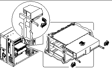
Pull the module ejection levers out and away from the CPU module to disengage the module from its main logic board connector.
The ejection levers are located on each side of the front of the CPU module. Using your thumbs, rotate the levers away from the center of the CPU module.
Figure 6-7
-
Pull evenly on the corners of the CPU module and slide it all the way out of the CPU card cage.
Place the CPU module on an antistatic mat.
What Next
To replace a CPU module, complete this task:
How to Install a CPU Module
Before You Begin
Know the configuration guidelines for installing CPU modules, see:
Complete these tasks:
What to Do
-
In the CPU card cage, locate the slot for the CPU module that you are installing on the main logic board.
-
Align the edges of the CPU module board with the grooves in the CPU card cage, and ensure that the ejection levers are open.
-
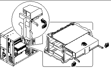
Slide the CPU module evenly into the grooves in the CPU card cage.
Push until the CPU module board meets the connector at the back of the CPU card cage.
Figure 6-8
-
Engage the notch in each lever with its side of the CPU card cage.
-
Simultaneously push both levers toward the center of the CPU module until it is fully seated in its connector.
What Next
Complete the following task to reassemble the system:
When you are ready to restart the system, be sure to run POST and OpenBoot Diagnostic tests to verify that the system functions correctly with the new parts you have just installed. You must also perform a reconfiguration boot so that your system is able to recognize the new device(s). For additional information, see:
How to Remove a PCI Card
Before you Begin
Complete these tasks:
Video Demonstration
Figure 6-9

Click on the icon above for a video demonstration.
Click here for Appendix E, Video Player Help.
What to Do
-
Disconnect any external cable(s) from the external faceplate of the PCI card.
-
Disconnect all cables connected to the PCI card internal connectors.
-
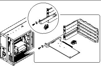
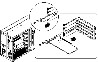
Remove the Phillips screw that secures the faceplate to the system rear panel.
Use a magnetized screwdriver, if possible, to prevent the screw from falling into the system chassis.
Figure 6-10
-
Pull the PCI card out of its slot.
Hold the card by the faceplate and its opposite edge, and pull each end in turn until the card is freed from its slot. Place the PCI card on an antistatic mat.
-
If you are not replacing the PCI card, install a PCI filler panel into the vacated slot.
Secure the filler panel with the screw from the PCI faceplate.
What Next
To replace a PCI card, complete this task:
How to Install a PCI Card
Before You Begin
Complete these tasks:
Read the documentation supplied with the PCI card for information about jumper settings, PCI slot requirements, and cable connections.
Know what type of PCI card you are installing or replacing and in which slot the card belongs on the main logic board; see:
Video Demonstration
Figure 6-11

Click on the icon above for a video demonstration.
Click here for Appendix E, Video Player Help.
What to Do
-
If you are installing a new PCI card, remove the filler panel from the appropriate slot. Otherwise go to step 2.
-
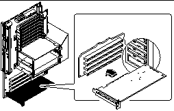
Insert the PCI card into the appropriate slot on the main logic board.
To install a PCI short card:
-
Secure the PCI card faceplate to the rear panel with the Phillips screw.
-
If necessary, connect any internal cables to the PCI card's internal connectors.
Read the documentation supplied with the PCI card for information about jumper settings, PCI slot requirements, and cable connections.
-
If necessary, connect any external cables to the PCI card.
Read the documentation supplied with the PCI card for information about external cable connections.
What Next
Complete the following tasks to reassemble the system:
When you are ready to restart the system, be sure to run POST and OpenBoot Diagnostic tests to verify that the system functions correctly with the new parts you have just installed. You must also perform a reconfiguration boot so that your system is able to recognize the new device(s). For additional information, see:
How to Remove the SSP Paddle Card
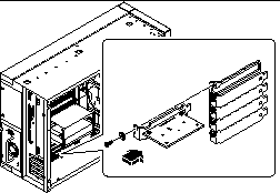
The System Service Processor (SSP) paddle card is mounted in the top slot opening in the system's rear panel.
Before you Begin
Complete these tasks:
Video Demonstration
Figure 6-14

Click on the icon above for a video demonstration.
Click here for Appendix E, Video Player Help.
What to Do
-
Disconnect any cables from the external faceplate of the SSP card.
-
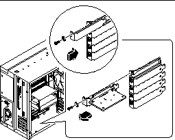
Remove the Phillips screw that secures the card faceplate to the system rear panel.
Use a magnetized screwdriver, if possible, to prevent the screw from falling into the system chassis. Save the screw for when you install the replacement SSP card.
Figure 6-15
-
Remove the SSP card from its rear panel opening.
-
Disconnect the SSP data cable from the main logic board at connector J4201.
-
Place the SSP card and data cable on an antistatic mat.
-
If you are not replacing the SSP card, install a PCI filler panel into the vacated SSP slot.
Secure the filler panel with the screw from the PCI faceplate.
What Next
To replace an SSP card, complete this task:
How to Install the SSP Paddle Card
Video Demonstration
Figure 6-17

Click on the icon above for a video demonstration.
Click here for Appendix E, Video Player Help.
What to Do
-
Connect the SSP data cable to the main logic board at connector J4201.
-
Insert the SSP card into the SSP rear panel opening.
The SSP paddle card mounts in the top slot opening in the system's rear panel.
Figure 6-19
-
Secure the SSP card faceplate to the rear panel with the Phillips screw you removed earlier.
Use a magnetized screwdriver, if possible, to prevent the screw from falling into the system chassis.
-
Reconnect any external cables to the SSP card's external connectors.
What Next
Complete the following task to reassemble the system:
When you are ready to restart the system, be sure to run POST and OpenBoot Diagnostic tests to verify that the system functions correctly with the new parts you have just installed. For additional information, see Chapter 12, Diagnostics and Troubleshooting.
How to Remove the NVRAM/TOD Module
This procedure must be performed by a qualified service-trained maintenance provider. Persons who remove any of the outer panels to access this equipment must observe all safety precautions and comply with skill level requirements, certification, and all applicable local and national laws.
Before You Begin
Complete these tasks:
What to Do
-
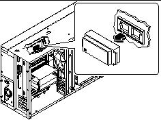
Locate the NVRAM/TOD module on the main logic board.
The NVRAM/TOD module is located at board address U2706.
-
Grasp the NVRAM/TOD carrier assembly by the edges and pull out the NVRAM/TOD module.
Place the NVRAM/TOD module on an antistatic mat.
Figure 6-20
What Next
To replace the NVRAM/TOD module complete this task:
How to Install the NVRAM/TOD Module
This procedure must be performed by a qualified service-trained maintenance provider. Persons who remove any of the outer panels to access this equipment must observe all safety precautions and comply with skill level requirements, certification, and all applicable local and national laws.
Use only NVRAM/TOD modules that have been specifically programmed for a Sun Enterprise 250 server.
What to Do
-
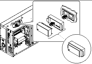
Insert the NVRAM/TOD module into its socket on the main logic board.
The carrier is keyed so that an NVRAM/TOD module can be installed only one way.
-
Push down on the NVRAM/TOD module until it seats firmly in the socket.
Figure 6-21
What Next
Complete the following task to reassemble the system:
Note -
If you are installing a new NVRAM/TOD module, the NVRAM/TOD must be programmed by a Sun authorized service representative before your system can resume normal operation.
When you are ready to restart the system, be sure to run POST and OpenBoot Diagnostic tests to verify that the system functions correctly with the new parts you have just installed. For additional information, see Chapter 12, Diagnostics and Troubleshooting.
- © 2010, Oracle Corporation and/or its affiliates

