What to Do
-
Lift the disk cage assembly into the side of the chassis.
Orient the disk cage so that the open drive bays are facing the front of the chassis. Grasp the free end of the LED ribbon cable (from the LED/keyswitch assembly) and pull it out the front of the disk bay opening to make room for the disk cage.
-
Align the screw holes on top of the cage with the captive screws in the upper part of the chassis.
-
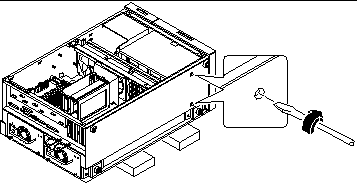
From the top of the chassis, use a long flat-blade screwdriver to partially tighten the two captive screws that secure the disk cage to the chassis.
Insert the screwdriver through the two access holes on top of the chassis to tighten the screws. Before tightening the screws fully, ensure that the two bottom screws are fully tightened (see Step 5). Finish tightening the top two screws only after the bottom screws are tightened.
 Caution -
 Take care to avoid damaging any cables that may be located near the captive screws.
-
Carefully lower the chassis onto its closed side.
Enlist the help of another person to accomplish this safely.
Do not lift the chassis using the plastic panels at the front or the side of the chassis.
Roll the system onto a solid surface that spaces the unit about 2 inches (5 cm) off the floor; for example, use a pair of wooden boards. Do not allow any of the weight to rest on the plastic panels at the front of the chassis.
-
From the underside of the chassis, use a large flat-blade screwdriver to tighten the two captive screws that secure the disk cage to the bottom of the chassis.
Figure 8-16

-
Stand the whole chassis upright.
Enlist the help of another person to accomplish this safely.
-
Finish tightening the two captive screws at the top of the disk cage.
-
Grasp the corner of the LED ribbon cable (hanging in front of the disk bay opening), and fold the cable under itself, so that the label at the end is facing up.
-
Feed the end back into the disk bay opening and route it on top of the disk cage toward the upper-left corner of the UltraSCSI backplane.
Arrange the middle portion of the cable so that it lies flat across the top of the disk cage at the front of the chassis.
-
Reconnect the LED ribbon cable to connector J0602 at the front of the UltraSCSI backplane.
This connector is located in the upper-left corner of the backplane (as viewed from the front). Make sure that the label at the end of the cable faces up. Press down the connector collar to secure the connection.
-
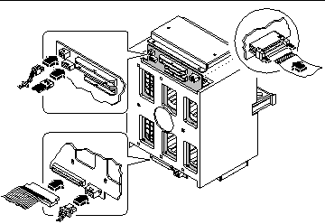
Reconnect the remaining cables to the rear of the UltraSCSI backplane:
-
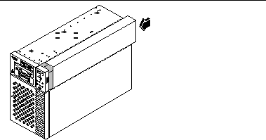
Replace the plastic outer panel that partially covers the top of the chassis:
-
Insert the hooks on the underside of the panel into the corresponding slots in the chassis.
-
Slide the panel toward the front of the system until the hooks engage the chassis, and the rear edge of the panel snaps into place.
Press along the bottom edge of the panel to guide it into place.
-
Figure 8-18

- © 2010, Oracle Corporation and/or its affiliates

